Native ESP8266 BrewPi Firmware - WiFi BrewPi, no Arduino needed!

Homebrew Talk - Beer, Wine, Mead, & Cider Brewing Discussion Forum

Help Support Homebrew Talk - Beer, Wine, Mead, & Cider Brewing Discussion Forum:

This site may earn a commission from merchant affiliate links, including eBay, Amazon, and others.
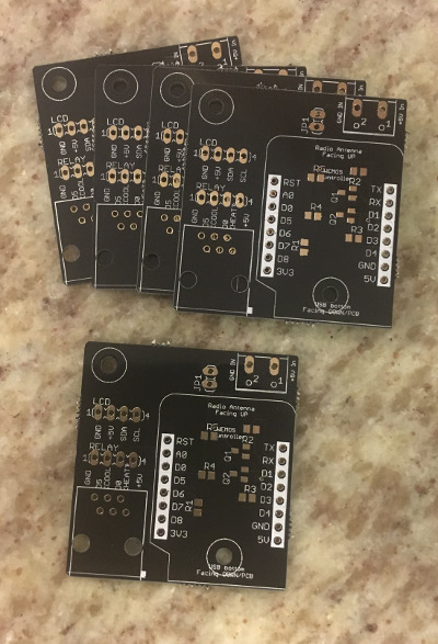
Two boards soldered up -now waiting for the resistors. I have a choice of 91% isopropyl or 70% ethyl alcohol to use as a flux cleaner which one should I use?
I'd use the 70% first and see if it takes care of it. I don't know about 91% Iso but when I use strong ethyl/methyl on finishes, I always water it down.

You can always rub it on the little ear that came stuck to the board (unless you threw it away) to make sure it does not damage the lacquer.
 
Just a quick update - we've had some friends staying with us for the past week and a half, so all brewing (and related projects!) ended up getting put on hold. They left earlier today, however, so I was able to start looking at some code this afternoon.

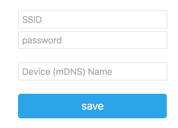
We're still a little bit off, but most of the work to add configurable mDNS entries is done. Added bonus - I think by doing this, I also get a convenient place to reset the EEPROM settings for a new install. Going forward, whenever you set the WiFi settings, the configuration for the firmware will be reset as well.

Edit - Holy crap that screenshot is huge. Sorry about that!

Screen Shot 2016-10-03 at 1.16.22 AM.png
 
We're still a little bit off, but most of the work to add configurable mDNS entries is done. Added bonus - I think by doing this, I also get a convenient place to reset the EEPROM settings for a new install. Going forward, whenever you set the WiFi settings, the configuration for the firmware will be reset as well.
Very cool! That seems reasonable and I'm looking forward to giving it a test run. I need to send off to China for a few more pieces ... one of my logic converters went missing and I need a couple more relay boards apparently.

I'm still wondering how I'll fit this in a box. Using a power outlet is easy ... using a second outlet for the phone jack is nice and clean but starts to limit the box choices unless you print or have one cut custom.

Can anybody post a picture of a working unit?
I've posted a few. What do you need to see specifically? If I don't have one I can take one when I get home.
 
Very cool! That seems reasonable and I'm looking forward to giving it a test run. I need to send off to China for a few more pieces ... one of my logic converters went missing and I need a couple more relay boards apparently.

I'm still wondering how I'll fit this in a box. Using a power outlet is easy ... using a second outlet for the phone jack is nice and clean but starts to limit the box choices unless you print or have one cut custom.

My plan at the moment is to print. You could potentially do a clean-ish build using a junction box, but you'd basically give up on the flexibility afforded by the RJ-11 jack (as well as potentially the LCD).
 
bringing this back up again, is it possible to run a wemos D1 firmware update over the air? i have one that works but the usb attachment is knackered, everything else works but i can't update the firmware to then update the screen etc to get it working, so an OTA update would be great. and for info my i2c LCD address is 0x3F which i guess is why it's not being picked up
 
bringing this back up again, is it possible to run a wemos D1 firmware update over the air? i have one that works but the usb attachment is knackered, everything else works but i can't update the firmware to then update the screen etc to get it working, so an OTA update would be great. and for info my i2c LCD address is 0x3F which i guess is why it's not being picked up

No, unfortunately, OTA flashing is not supported in this sketch. That is definitely the cause of the issue - if you got an LCD module with the 0x27 address it should work fine.
 
thanks for getting back to me, it's probably cheaper for me to wait for my replacement, shame i can't change the address of the module...

I'll try to make sure that i break the USB port after i've got it properly set up next time!!
 
thanks for getting back to me, it's probably cheaper for me to wait for my replacement, shame i can't change the address of the module...

I'll try to make sure that i break the USB port after i've got it properly set up next time!!

Indeed! As I mentioned in an earlier post, for the next one - be careful with the USB power supply you have it plugged into if that is how you choose to power it. A lot of the cheap knock-off power supplies output extremely dirty power which may be part of what fried the USB to serial chip in your D1 Mini.
 
Thanks , The RPI is to the left?Can you connect the RPI with bluetooth instead of the usb cable or will it connect with the esp8266?
The RPi is actually in my garage, the ESP8266 connects via WiFi. The USB cable is just for power; I could have used the 5V0 terminals to the right and left the USB unplugged.
 
It's easy to do so. I've got several on the desk. I had to steal a couple pieces this morning from one to put this together and take a quick pic. I have an order coming from China with more parts but till then I am swapping back and forth with regularity.
 
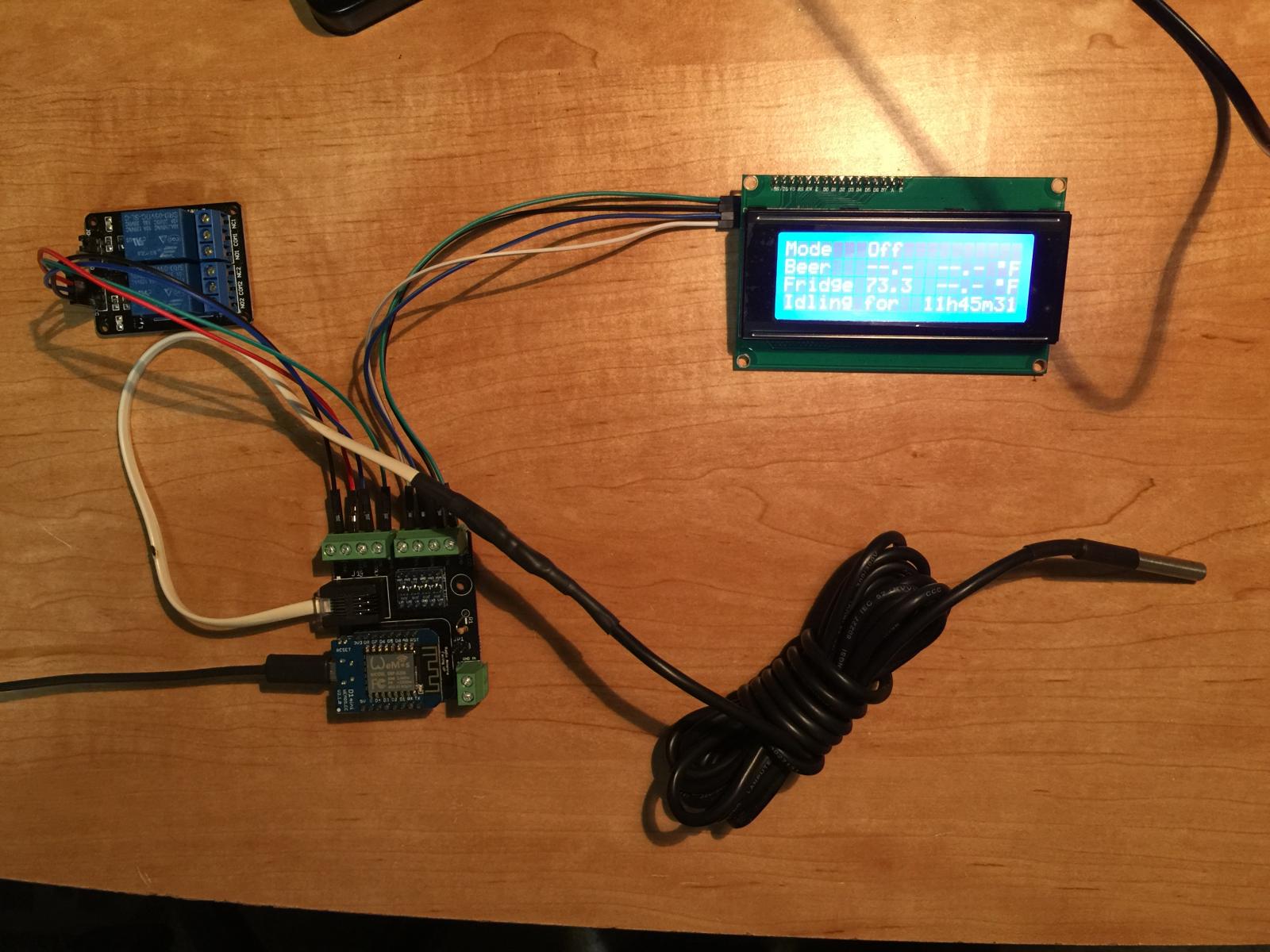
Ok so we're completely up and running [emoji106]🏻[emoji106]🏻 View attachment ImageUploadedByHome Brew1475659453.702208.jpg

I'm still waiting on my RJ12 connectors to arrive which is why I've connected direct to the ESP8266 but it works!

One issue I do have though is it takes forever to Script to start and RPI to communicate with the ESP8266 my config file isn't as simple as the one in the instruction video there is all the standard brewpi stuff commented out.

The start script button seems to have no effect either. All a bit strange.

But it works
 
I'm fairly new to all of this but having a lot of fun attempting to get it working. I have though hit a bit of a wall in terms of getting more than one sensor to be recognised. I've tried the "reset controller to factory defaults" but still when I refresh device list it only shows one temp sensor and 3 digital pins.
I tried it using fuscus with the two temp sensors in the same configuration and they both show up correctly so hopefully that indicates they are wired up correctly. I've also tried a couple of different power supplies in case that is an issue.
Is there something else obvious I'm missing? I should also point out I'm using a v0.9 esp8266 board rather than the WeMos one and the brewpi-esp8266.v0.3.wifi.bin firmware.
 
Ok so we're completely up and running
Congratulations!

One issue I do have though is it takes forever to Script to start and RPI to communicate with the ESP8266 my config file isn't as simple as the one in the instruction video there is all the standard brewpi stuff commented out.

The start script button seems to have no effect either. All a bit strange.
Mine seems to take a while to start as well, but I've not gotten the gumption to figure out why. Once it stars working I forget all about how I got there. :)
 
I'm fairly new to all of this but having a lot of fun attempting to get it working. I have though hit a bit of a wall in terms of getting more than one sensor to be recognised. I've tried the "reset controller to factory defaults" but still when I refresh device list it only shows one temp sensor and 3 digital pins.
I tried it using fuscus with the two temp sensors in the same configuration and they both show up correctly so hopefully that indicates they are wired up correctly. I've also tried a couple of different power supplies in case that is an issue.
Is there something else obvious I'm missing? I should also point out I'm using a v0.9 esp8266 board rather than the WeMos one and the brewpi-esp8266.v0.3.wifi.bin firmware.
You need to reset the ESP8266 as well after that, either with the button or a power cycle.

I don't know if that board would have any bearing on it or not, but that's what I had to do with the WeMos one.
 
Ok so we're completely up and running

One issue I do have though is it takes forever to Script to start and RPI to communicate with the ESP8266 my config file isn't as simple as the one in the instruction video there is all the standard brewpi stuff commented out.

The start script button seems to have no effect either. All a bit strange.

But it works

Congratulations!

What you're experiencing with the script is because of the order in which it does things:

1. Attempts to connect via serial
2. Times out
3. Attempts to connect via WiFi
4. Succeeds, Creates interface for brewpi-www to connect

It's steps 1 & 2 that cause it to take so long to start up. The controller itself should work during this time (the ESP8266) but it won't be seen by brewpi-script or brewpi-www.

I admittedly have no idea what the start button does (if anything). I believe that launching the actual script is handled by a crontab entry. The button may do the same thing the crontab entry does, but without looking at the code I'm not sure.
 
I'm fairly new to all of this but having a lot of fun attempting to get it working. I have though hit a bit of a wall in terms of getting more than one sensor to be recognised. I've tried the "reset controller to factory defaults" but still when I refresh device list it only shows one temp sensor and 3 digital pins.
I tried it using fuscus with the two temp sensors in the same configuration and they both show up correctly so hopefully that indicates they are wired up correctly. I've also tried a couple of different power supplies in case that is an issue.
Is there something else obvious I'm missing? I should also point out I'm using a v0.9 esp8266 board rather than the WeMos one and the brewpi-esp8266.v0.3.wifi.bin firmware.

I can't imagine that the difference in board would matter much, so long as the board you're using has sufficient flash space. Unfortunately, I haven't had the same issue in my setup, so I'm not sure how to diagnose this one. I'm building a new controller this weekend, though, so I'll see if it pops up then.

The only step I can think of to diagnose is to try using each sensor individually with the ESP8266 and see if they both work on their own. If one of them doesn't work, it may be something with that specific sensor.
 
Thanks for the tips. I tested with each temp sensor individually. One worked fine, the other was initially identified, but with a null value. After resetting to default and power cycle it no longer found it. So it looks like there's something it doesn't like about one of the sensors. Not sure if it's relevant, but the sensor that doesn't work has a 28-8 address rather than a 28-0 that I usually expect from these ds18b20 sensors. Also the initial readings of temperature when connected to the raspberry pi give 85C before subsequently giving the correct temperature. It looks like I'll be ordering some more sensors!
 
It kind of sounds like your data and vcc lines might be swapped over as mine does that if I accidentally get them out it wrong. But it sounds like you might have done that.
 
I discounted the option that I might have wired them the wrong way round as they both work when connected to the raspberry pi in that configuration.
I actually purchased an extra temp sensor in case one of them didn't work but somehow dx managed to send me a disposable razor instead!
 
I approve of this message! :eek:nestar::eek:nestar::eek:nestar::eek:nestar::eek:nestar:

I was going to ask about it previously, but since I'm basically putting things on a list for you to do I figured I'd keep my mouth shut. ;)

You can put me down as a person who would definitely use the design.

If you want to go crazy, drop in high voltage as well with a power supply and you have a one-board solution. :D

That would be realy nice :)
 
Welp, I got two of the PCBs soldered up, tested, and working great. Went to print an enclosure, and managed to have my 3D printer break. Fun times!

Replacement parts are on their way, but are shipping from the Czech Republic. Fingers crossed that they arrive next week. :(
 
Hi guys,

So I want to use an original Wemos D1 for this project, can I just follow the same setup? Is the firmware going to work like it does on the mini?

Cheers!
 
Yep, it should. Same with other NodeMCU boards, you just have to be mindful of the pinout.

Yep the pinout was a tad different for me. Fortunately you have it set in the code to show what pins to use, which to be honest, I totally overlooked.

I also had to do the 'restore to default configuration' thing as my devices wouldn't save when I was setting them up.

I haven't got the lcd set up yet as the one I have had the little I2C board removed for the diy brewpi project (what up fuzzewuze!) so it will be interesting to see if those pins are the same too.

Also note that the cheap fake wemos minis are really bad in the fact that they seem to run hit and miss when configuring the wifi - just noting all this for future reference, for people searching for solutions at some point. (People like me ;))

All setup now running and hope to wake up and see a solid result which I expect.

Cheers for this alternative, it's a great solution!
 
Last edited:
Yep the pinout was a tad different for me. Fortunately you have it set in the code to show what pins to use, which to be honest, I totally overlooked.

I also had to do the 'restore to default configuration' thing as my devices wouldn't save when I was setting them up.

I haven't got the lcd set up yet as the one I have had the little I2C board removed for the diy brewpi project (what up fuzzewuze!) so it will be interesting to see if those pins are the same too.

Also note that the cheap fake wemos minis are really bad in the fact that they seem to run hit and miss when configuring the wifi - just noting all this for future reference, for people searching for solutions at some point. (People like me ;))

All setup now running and hope to wake up and see a solid result which I expect.

Cheers for this alternative, it's a great solution!

Yeah - the first post in this thread is too old to edit, unfortunately, and the pinout in it is old. As you noted, the pins are in the code (and should hopefully be updated in the read me on the repo as well) but it still could be confusing.

The restore to default thing should be fixed in an upcoming release along with the option to change the mDNS name. The code for both of these is working on the build I just assembled, but is still missing one critical piece (ironically - basic C++ string validation is tripping me up. Too many years using regex). Hoping to have the release for that very soon.

Good to know on the knock off boards. The one I just flashed is the new "WeMos Mini D1 Pro" which works perfectly. I've got a knock off board sitting on my desk as well - I'll give it a shot at some point and report back.
 
Well I have just gotten up and the fermenter controller is mint, all going well.

Is the pinout the same for the I2C LCD (pins 01 and 02?)

I had been following the instructables website directions, which must be a bit old because there were a few things in the installation of the software I had to do slightly different.

Yeah, I need to go back and reread the documentation/instructable to make sure it is all up to date. The current pinout is as documented on GitHub which as you noted has the LCD on pins 1 & 2:

D0 - Heat
D1 - I2C SCL
D2 - I2C SDA
D3 - Buzzer (currently unsupported)
D4 - N/C
D5 - Cool
D6 - OneWire Data
D7 - Door (Untested)

Side note - if anyone has tested the door pin, let me know, and I'll remove untested from the description. :)

If you recall what you had to do differently, what you had trouble with, or what was unclear, I'll try to address it when I go back through the docs.
 
I had been following the instructables website directions, which must be a bit old because there were a few things in the installation of the software I had to do slightly different.
What did you note that was different? I recently edited the docs and I thought I got everything.
 
What did you note that was different? I recently edited the docs and I thought I got everything.

So there was some command line stuff that was a bit different, but minor.

I followed the tutorial here.

Pretty minor, but if if any one isn't quite confident or up to speed with command line stuff it could be a struggle.

Also the pin out in the diagram isn't current - see step 6.

There also isn't mention about the wifi-reset.bin flash which is good to know if you bugger up the wifi setup!
 

Latest posts

Back
Top