My Fermentrack Build

Homebrew Talk - Beer, Wine, Mead, & Cider Brewing Discussion Forum

Help Support Homebrew Talk - Beer, Wine, Mead, & Cider Brewing Discussion Forum:

This site may earn a commission from merchant affiliate links, including eBay, Amazon, and others.
Phase 3
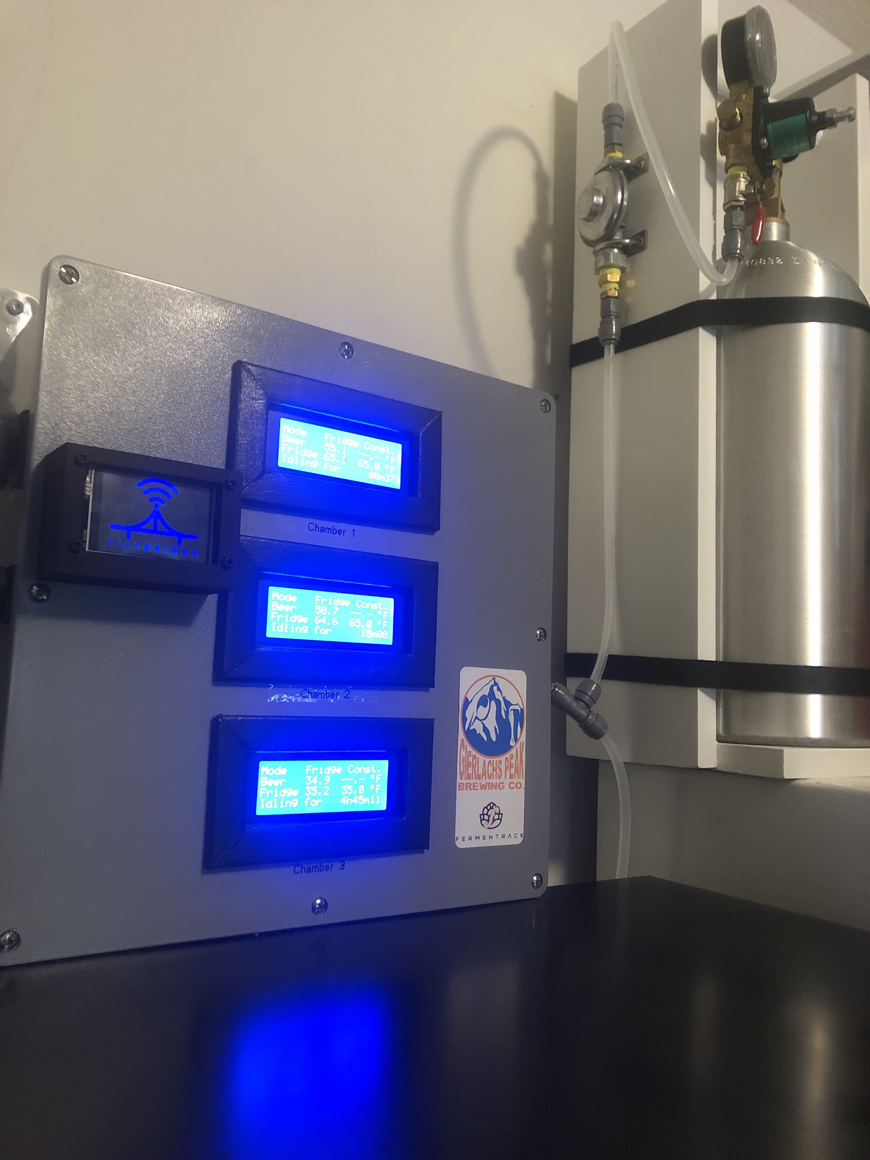
3 Instance Main Control Box Build

As I said in Phase 2, I really don’t want to have to open and enter the project box holding the controllers. If I want to flash a D1 Mini, I don’t want to open the box. If a temperature probe goes bad, I don’t want to open the box.

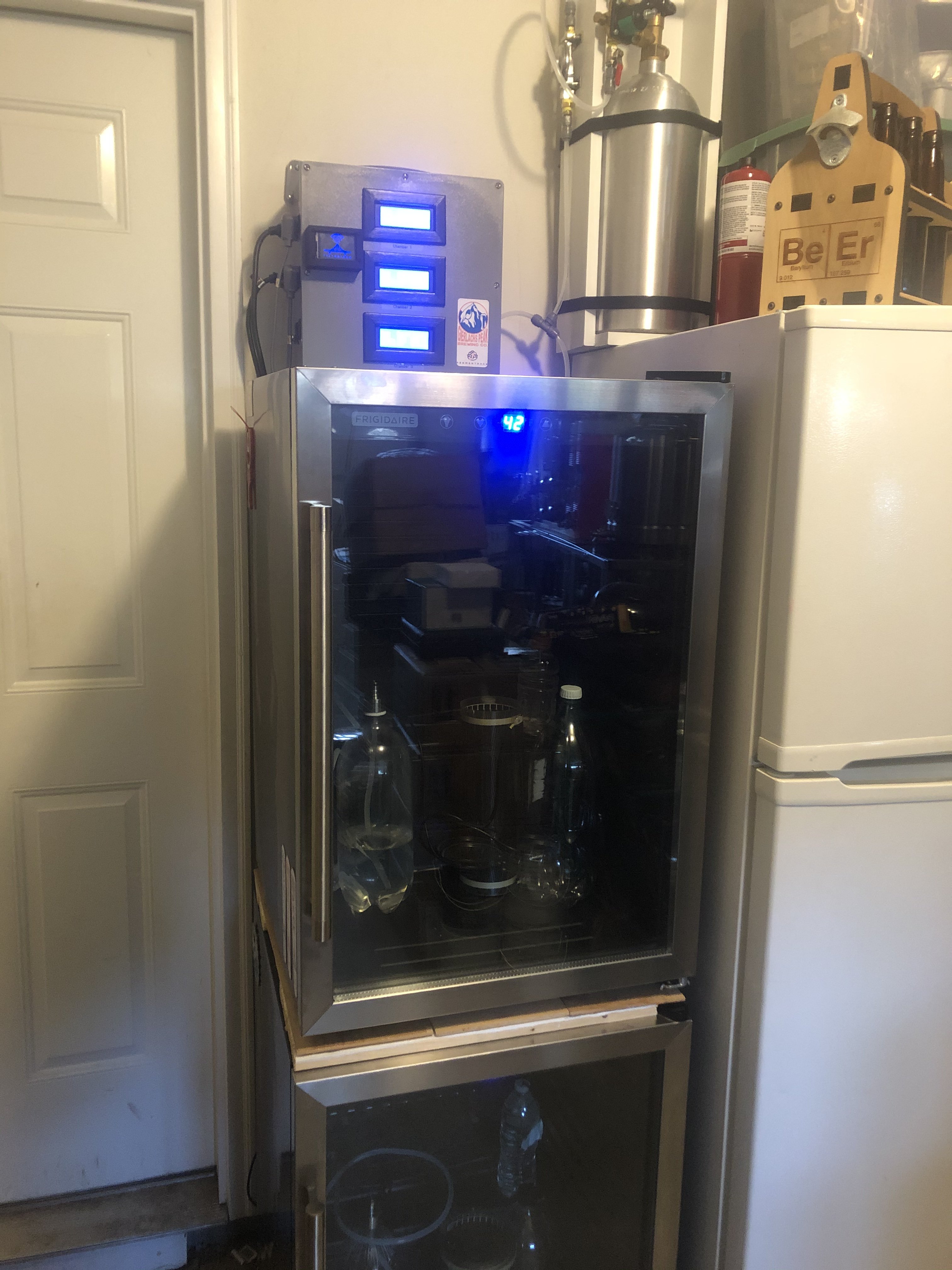
I only have one (1) fermentation cooler, but a second will be added. I also currently have a fridge used to lager (hold Temp at 40F). With an eye to the future, this is a 3 instance build. Two (2) controllers will be held at Beer Constant/Profile and one (1) controller will be at Fridge Constant.

Looking at the module sizes and how I wanted to position the modules, I decided on a 12” x 12” x 6” Junction Box. This box is huge and I thought I made a mistake going with the larger box. As I assembled the control box, for me, this was the perfect size for a 3 instance control box.
  1. Purchase a project box that is large enough to comfortably hold as many Controller Instances as desired
  2. Cut a piece of Aluminum to fit inside project box to act as a sub-board.
  3. Place Modules on aluminum and mark mounting hole locations.
  4. Drill holes in aluminum where mounting holes were marked.
  5. Add standoffs to mounting holes.
  6. Determine location of Keystone Plate(s)
  7. Cut opening to fit Keystone Plate(s)
  8. Install Keystone Plate(s)
  9. Determine location of 3 Pin Inlet Power Plug Socket
  10. Cut opening to fit Socket
  11. Install Power Plug Socket
  12. Determine location of 3 Pin Power Socket Panel Receptacle AC125V 15A.
  13. Cut opening(s) to fit Receptacles
  14. Install Receptacles
  15. Determine location of LCD Modules on the Project Box lid
  16. Cut openings to fit LCD Modules
  17. Install LCD Modules to the Project Box lid
  18. Solder the following on the ESP8266 Breakout Board for BrewPi:
    1. 2-pin Screw Terminal Block
    2. RJ45 PCB Socket
    3. 1206 SMD 100uf Capacitor (to C1)
    4. 0805 SMD 4.7K Resistor (to R1)
    5. 0805 SMD 10K Resistor (to R2, R3, R4, R5)
    6. Mosfet SMD (to Q1, Q2)
    7. Male Pin Headers To LCD, Relay, and JP1 Contacts
    8. Female Pin Headers to contacts for the D1 Mini.
  19. Solder Male Pin Headers to the D1 Mini (make certain Male Pins point away from the D1 antenna)
  20. Secure PS Module, Relay Module, and completed ESP8266 Breakout Board to the standoffs.
  21. Insert aluminum sub board with attached modules into the project box.
  22. Run Electrical wires appropriately (I referenced Thorrak’s how to site tinybat.ch to wire accordingly) from the Inlet Socket to the PS. From the PS to the ESP Breakout Board. From the Power Receptacles to the Relays, and all the points/connections in between.
  23. Install the USB and RJ45 Keystone Inserts into the Keystone Plate(s)
  24. Run Ethernet Patch Cable from RJ45 Keystone Insert to RJ45 Socket on the ESB Breakout Board.
  25. Connect D1 Mini to the ESB Breakout Board
  26. Run USB Patch Cord from USB Keystone Insert to D1 Mini.
  27. Connect Female to Female DuPont connectors appropriately from the ESB Breakout Board to the 2 Channel Relay.
  28. Connect Female to Female DuPont connectors appropriately from the ESB Breakout Board to the LCD Module.
Additional (optional) Steps
  1. Added handle to top of case
  2. Construct/install wood frame to trim around LCD Screen
  3. Ran Trim Lok edge trim around the Aluminum sub-boards (not only to protect skin and wires from getting cut, but if measured and cut properly, acts as a friction mount and holds the sub-boards in place to the project box)
  4. On the Power Supply Modules.
    1. Desoldered and removed inlet power connectors
    2. Soldered in more robust 2-Pin Screw Terminals
  5. Used Female DuPont connectors to open wire ends to connect PS to ESB Breakout Board.
  6. Used shims with the 3 Pin Receptacles to get a snugger fit
  7. Had to adjust LCD contrast using the potentiometer on the back of the LCD Screen
  8. Added labels to identify LCD Screens, Inputs, and Outputs.

View attachment 623557 View attachment 623559 View attachment 623561 View attachment 623563 View attachment 623564 View attachment 623566 View attachment 623567 View attachment 623568 View attachment 623569 View attachment 623570

I am sure I overlooked this, but where so the 3 USB A connections go to on the bottom of the Main Control Box? I get the network cables would go to the RJ45 Breakout Board Control Box.
 
...for future generations....

I run USB patch cables (x3) from my D1 Minis to the USB Keystones inside the control box.

From the outside bottom of the control box, the USB ports will not be used often. The reason I designed the box, the way I did, was to keep me from opening the whole thing up if I had to flash a mini.

I am a firm believer that many people experience issues with these DIY builds due to loose/bad/improper connections. If I could design a build that would lessen the threat of jostling/moving components and wires around, I would be better served.
 
So if I am mounting the main box right next to my fermenters, what is the advantage or use for running Titlebridge vs just connecting directly to the Tilts?

I assume the obvious reason is you have the visual screen readouts of the SGs, but what is there beyond that?

FYI Thorrak had some extra parts I needed in addition to the PCBs. I think I will have this all sourced and received this week and look forward to getting this up and running :)
 
If your RPi running Fermentrack will be next to your Fermentation Chambers, then no, you would not necessarily need TiltBridge. However, if your RPi is far away, there’s a good chance the Tilt Bluetooth signal would not reach your RPi and you would not be able to monitor SG through Fermentrack.

The TiltBridge takes the Tilt Bluetooth signal and converts it to WiFi for increased range.
 
Last edited:
Phase 4
Controller Flashing/Controller WiFi Connection Set-up/Adding a new Temp Controller

Make life easy on yourself and Flash your D1 Mini’s (or whatever approved device) through Fermentrack. My recommendation, flash the system test first. This will let you know if your wiring, probes, and general set-up is in working order. Once the test is complete, flash with the appropriate version of BrewPi.

The next step is to connect your D1 Mini (or whatever Approved device) to your network. I feel like a heel, but this step stymied me. When you first power up your D1 Mini (either through USB or 5v PS) it will broadcast an Access Point (AP) for about 5 minutes. During this 5 minutes, you want to use your smart phone, tablet, computer, or whatever you have to connect to the AP. When you connect, you will set the WiFi. Locate your network SSID, type in the network password, and connect. You’re D1 Mini is now connected to your network and you can work through Fermentrack to add a new temp controller.
 
Last edited:
I did, thanks though.

Your build was my inspiration 😊

I still need to add the TiltBridge. Wired, not mounted yet.
 

Attachments

  • image 2.jpg
    image 2.jpg
    2.5 MB · Views: 83
  • E5227670-AEF4-40BC-8797-88B1247EA22B.jpeg
    E5227670-AEF4-40BC-8797-88B1247EA22B.jpeg
    2.4 MB · Views: 78
Hoping this is a good place to ask; but did you have any issues with flashing/setting up your tiltbridge TFT variant? I'm attempting to flash it the ESP32 board with TFT via Fementrack, and it'll finish. Then I don't get anything on the screen, and there's no TiltBridge WiFi to connect to either. The OLED has had the best success for me so far.
 
Hoping this is a good place to ask; but did you have any issues with flashing/setting up your tiltbridge TFT variant? I'm attempting to flash it the ESP32 board with TFT via Fementrack, and it'll finish. Then I don't get anything on the screen, and there's no TiltBridge WiFi to connect to either. The OLED has had the best success for me so far.

The TFT variant (unlike the OLED variant) requires a connected TFT screen using the D32 Pro pin mapping that the firmware can see/interact with to boot. If your TFT screen isn't connected using the correct pinout or has any kind of issue responding when the firmware looks for it, then the firmware will hang.

The OLED variant doesn't care and will boot regardless of whether a screen is present/can be detected or not.
 
Hey @Thorrak, thanks for the quick reply!

When you say the firmware hangs, do you mean on bootup of the ESP32? Would a signal of it not working possibly be a constantly blinking red LED? I'm fairly new to setting this up, so I apologize if this is covered somewhere else and I didn't find it. Feel free to point me in the right direction.

Are there any steps/troubleshooting I should follow to ensure I have the right pinout/connection? The screen does light up, but that red LED constantly blinks despite flashing, and it never advertises a WiFi signal.
 
just to add-on my experience with what @Thorrak has said.

No, I didn’t have any issues with my TFT/D32Pro. However, I didn’t flash TBridge via Fermentrack. Instead, I used BrewFlasher.

“Firmware hanging” is yes, during boot-up of the TBridge. You’re not seeing an SSID and not being able to connect via WiFi because your “ESP32” board is stuck.

You may want to share a picture of your TBridge set-up and post it in the following thread with some background on your problem.

https://www.homebrewtalk.com/threads/tiltbridge-tilt-to-wifi-device-for-tilt-hydrometer.664368/
Someone in that thread may have encountered your same issue and resolved it.
 
I've been having issues with using BrewFlasher or the pyflasher for that matter. I suspect that is more on me, but I couldn't figure it out. Fermentrack has been good for me with flashing so far, so I've leaned on it a bit.

Thanks, for the link!
 
hmm, that's pretty strange to have issues with BrewFlasher. BrewFlasher was developed to relieve the pain point of flashing devices.

Any questions or problems concerning BrewFlasher can be directed at this thread:
https://www.homebrewtalk.com/thread...ashing-esp8266-esp32-brewing-projects.674823/
Your in a pretty odd circumstance. Looking at the picture you supplied in the TBridge thread, it looks like you're running a D32 Pro, and I know the TFT cable only attaches to each device in one configuration. Why things aren't working doesn't make sense, but if you're struggling with BrewFlasher...maybe that tells @Thorrak something.
 
Thanks again for the link, I'm not sure why I didn't come across these when googling. I'm almost certain there's an issue with a driver or something similar that prevents me from using brewflasher correctly. I tried it with the OLED variant and had the same "no serial found" issue. I'm sure with a little more effort I can get that working but like I said, I'm fiarly new to some of this stuff. FWIW it was the same issue on 2 different Windows PCs. I'll peruse the BrewFlasher thread though, thanks!
 
If you are trying to have BrewFlasher find the serial port, you need to disable BlueTooth otherwise you'll have problems with BrewFlasher finding it.

The other common problem is cable. Not all USB cables have a data line and some are for charging only. Using a cable that is only for charging could cause the issue you describe.
 

Latest posts

Back
Top