Sorry, Gadjobrinus. Can't always be on call to respond to HBT forums.
")
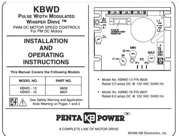
Motor Connection:
So, for the motor connection, white from "CW (-)" to A2; black from unlabeled on back of motor to A1. Green is ground, but per below, I don't know where to connect this ground line.
Correct on the motor connections. More on the ground below.
For the AC cord,
So, White to L2, Black to L1, Green to ground, though I don't know where to hook the ground wire up, because unlike other models, I see no ground terminal on the board.
I also don't know how to "connect chassis to earth."
The ground from your power cord is usually green, connected to the round ground pin on your 3-wire plug. If the KBWD-16 has a metal chassis, then you'd connect the wire here; if there's no way to connect, it's probably OK to not make a connection. However, you'll want to connect the ground from the AC cord to the ground on the cord going to motor, which then gets attached to the motor's GR terminal. This ground is "earth ground"; in the absence of a fault, there should never be any current flow on this wire.
Potentiometer: I know the proper connections. I just don't know the kind of wire you use for things like this (would imagine direction and on/off switches use the same wire?).
This can be smaller wire, maybe anything 18-24AWG stranded. If you have excess wire from an old ceiling fan or anything, it will do. Make it long enough to be easy to work with to wherever you will mount the pot. Twist the 3 wires together (so best to have 3 different colors to make it easy to identify the 3); this is a low-level signal, but mildly susceptible to noise, which is why you twist the wires.
Fuses:
AC Fuse:
KB Part 9746. 10 Motor Current (DC Amps), Fuse Rating 15 Amps (AC). Will try to find a way to connect the fuse box inside the enclosure. White to L2, Black to fuse to L1.
Motor Fuse: I presume part no.
9742. 2.5 Motor current (DC A), 4 A (AC). Fuse box, same, will try to find a place to install it. White to fuse to A2. Black to A1. (This seems weird to me - isn't B alway hot, and white neutral?).
You can buy any standard fuses from a hardware or auto parts store, and can get a fuse block from Radio Shack, Amazon, or auto store (probably). Wire colors are standard convention for AC, but the color really doesn't matter for the motor. You really have just DC+ & DC-.
still looking to see if it's possible to put an on/off and direction switch. Also looking for a suitable enclosure.
The on/off switch can be any
SPST toggle switch rated for 250VAC minimum, or just a standard wall switch, depending on how you mount it. It will just be in series with the input AC fuse (hot AC input).
For direction, you'll place an on/off/on DPDT switch like
this one I used between A1/A2 and the motor, like below. I assume you have a multimeter to check connections or voltages. If you don't, buy an inexpensive one for <$10 from Sears, Amazon, etc. The nice thing about installing the polarity switch is that you don't really care about the motor direction. Just wait to label FWD/REV on your switch after you figure out which direction is which (or if you're anal, just swap the leads on the motor if you want to reverse it after testing.
Finally, the enclosure can be a plastic "project box" or a metal one. Make it big enough to fit the KBWD-16, to mount the pot and switches, and fuses, maybe 4x6x2 or so. It really depends on how you're mounting everything. Plastic is much easier since you'll be drilling a bunch of holes.


![Craft A Brew - Safale BE-256 Yeast - Fermentis - Belgian Ale Dry Yeast - For Belgian & Strong Ales - Ingredients for Home Brewing - Beer Making Supplies - [3 Pack]](https://m.media-amazon.com/images/I/51bcKEwQmWL._SL500_.jpg)