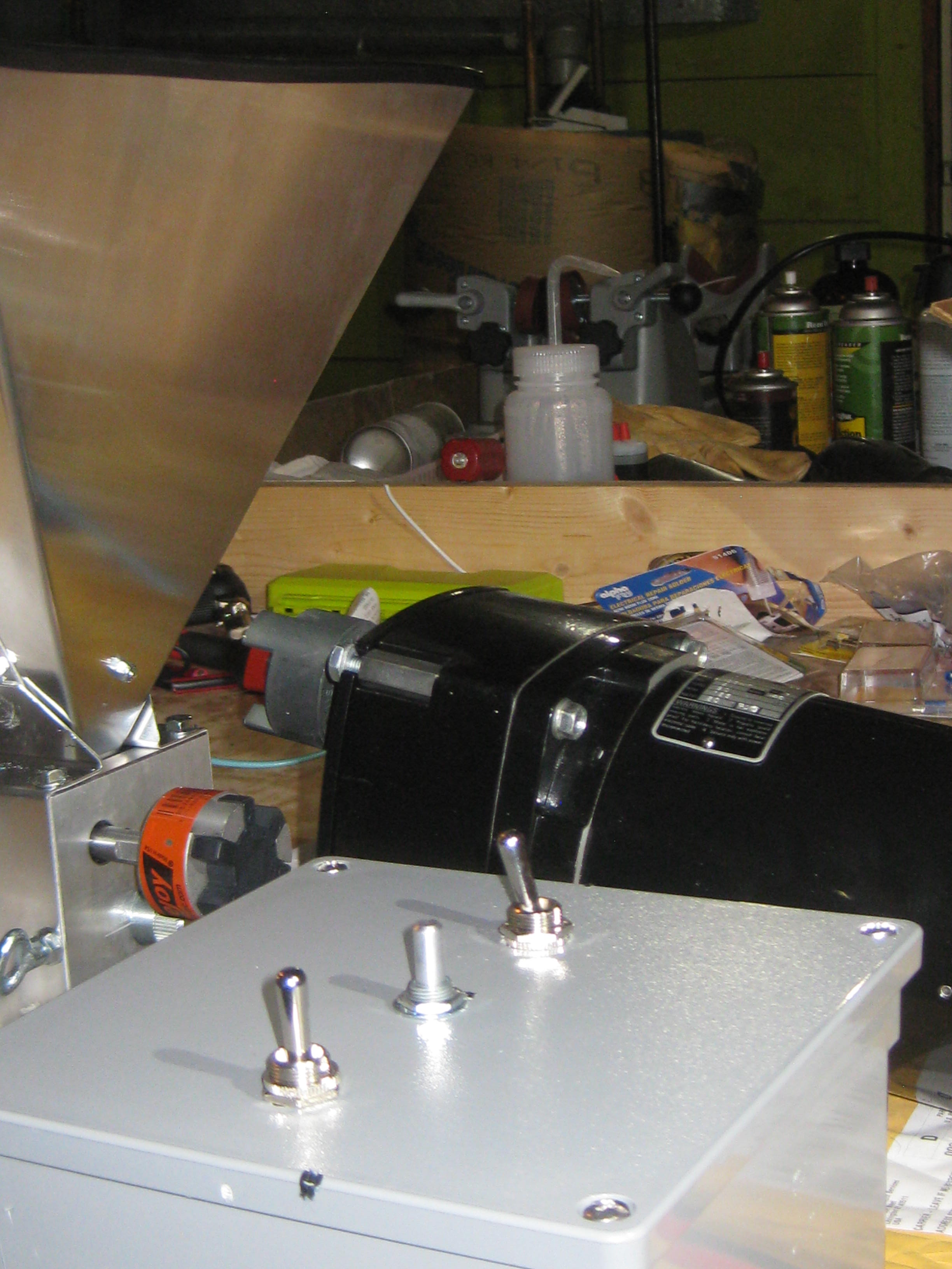
The black circles really just symbolize the switches, but yes, there is one terminal per circle. The 2 on the left are the center terminals on the switch, referred to as the commons, since they connect to the 2 poles of each switch. Just wire those to A1 & A2.On the directional switch, I meant the two left-most connections showing in your diagram (I presume that's what the black circles are, on that directional toggle switch since there's 6 connections on the switch and 6 circles on your diagram), one on A1, and one on A2.
If you get the switch in hand and then measure the connections with an Ohmmeter with the switch in both positions, it should become clear to you. If it's not already obvious, the middle position for the switch leaves everything disconnected (e.g., OFF).


![Craft A Brew - Safale BE-256 Yeast - Fermentis - Belgian Ale Dry Yeast - For Belgian & Strong Ales - Ingredients for Home Brewing - Beer Making Supplies - [3 Pack]](https://m.media-amazon.com/images/I/51bcKEwQmWL._SL500_.jpg)


