
KyleWolf
Well-Known Member
Hi everyone.
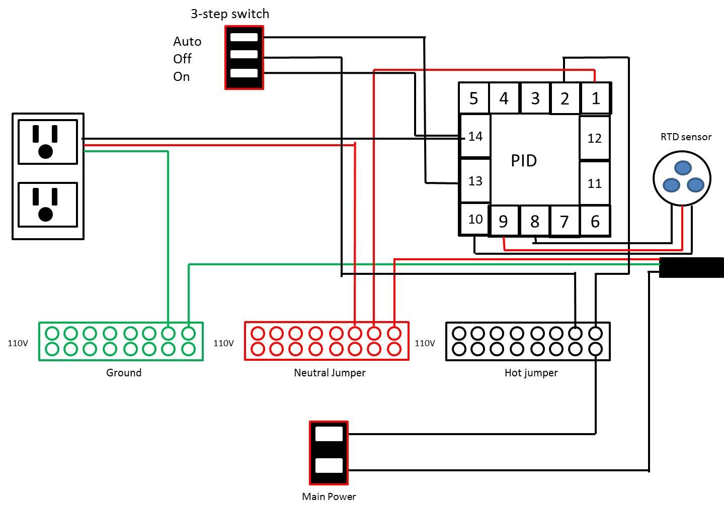
I am designing a fairly simple HERMS set-up. Right now I am planning on starting off at 1 pump and eventually upgrade to a 2-pump system. I am designing my PID-Controller and wanted to make sure I have the diagram correct. The idea is simple. a 3-way switch for "Auto, Off, and Manual" for the pump that recirculates the mash through the HLT. Manual is just "On" for all other functions for the pump not pertaining to the mash (sparge, chilling, etc) and Auto will have the pump turn on and off according to the PID and RTD sensor that goes to the mash-tun.
The idea for the design is so I could add parts of the system "al a carte" as the equipment is purchased (second PID, gas valve, and pump for HLT, PID for boil kettle, etc).
Really I just want to make sure the design I have will do what I want it to do. Which again is basically...
1) Auto-turn on of off the pump according to the temp measured by the PID/RTD sensor (Auto)
2) Turn off the pump (off)
3) Have the pump run continuously (Manual)
Thoughts/Suggestions/Etc are always welcome! Thanks a lot.


