Love controls troubleshooting

Homebrew Talk - Beer, Wine, Mead, & Cider Brewing Discussion Forum

Help Support Homebrew Talk - Beer, Wine, Mead, & Cider Brewing Discussion Forum:

This site may earn a commission from merchant affiliate links, including eBay, Amazon, and others.

Dminetti

Member
Joined
Nov 3, 2020
Messages
15
Reaction score
1
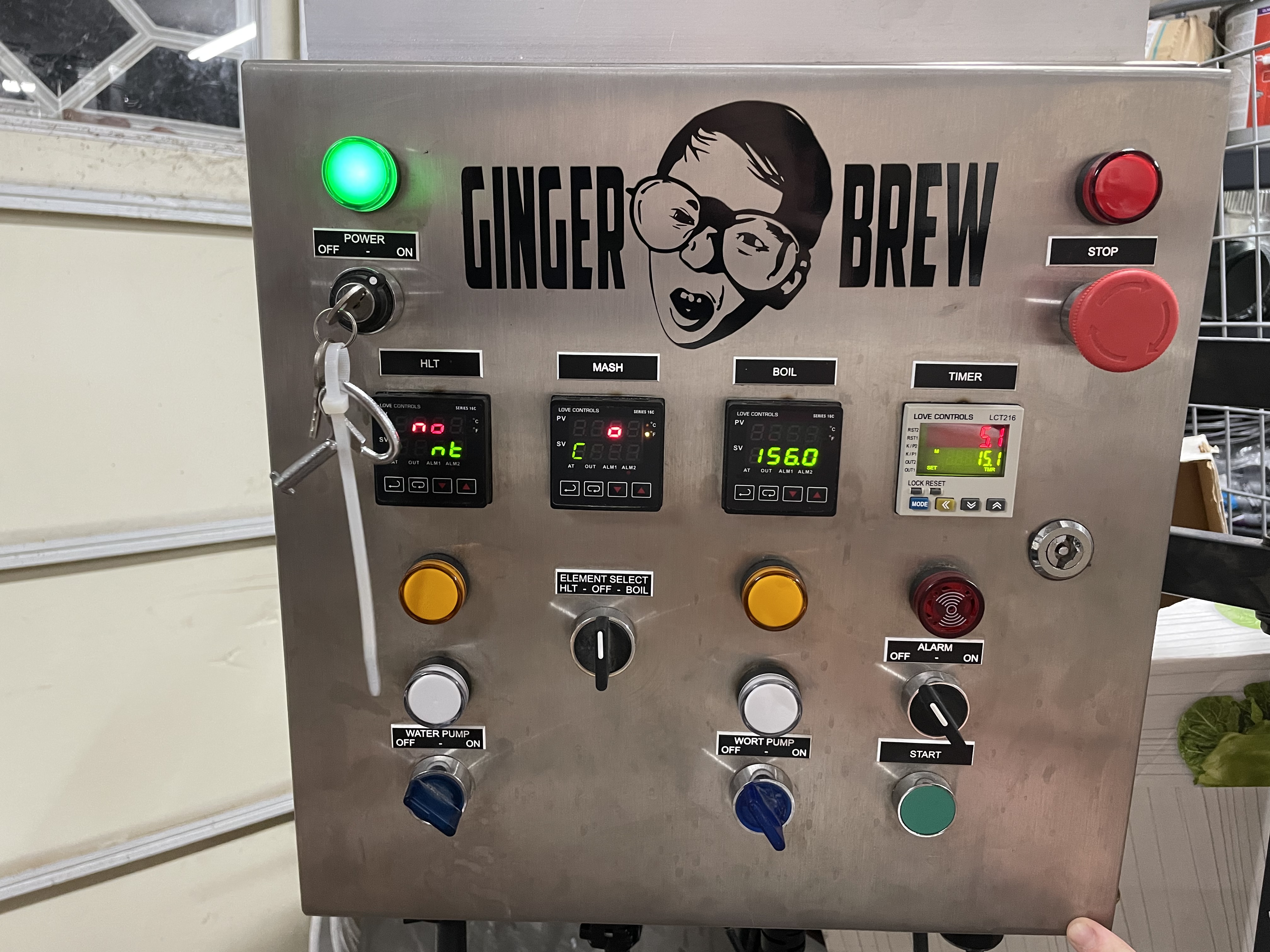
I recently purchased a second hand electric brewing supply 30amp panel and Im having issues with the Love Controls PID’s. Curious if anyone has any advice for the issues below.

1) RTD probe temps fluctuate constantly. I’ve tried adjusting the deviations in settings, but when checking against accurate thermometers the PID readings consistently overshoot on heat up and undershoot when liquids are cooled.

2) The boil controller will not reduce output percentage when set in manual mode. I’ve set the controller in manual mode within settings, but when temp hits set point and I adjust output percentage, the element continues to fire at 100%.

3) Again with the boil controller, I’ve tried testing the “stop” mode when operating in manual, but the element continues to fire. The output LED on the controller turns off, but the element continues to fire.

I’ve been adjusting about every setting available with no success in remedying the issues above. Any advice would be appreciated before I spend another few hundred to upgrade to auber EZ boil controllers….

Thanks in advance.
 
1) RTD probe temps fluctuate constantly. I’ve tried adjusting the deviations in settings, but when checking against accurate thermometers the PID readings consistently overshoot on heat up and undershoot when liquids are cooled.
Overshoot and undershoot with PIDs is characteristic of the P, I, & D parameters not being optimized for the thermal response of the system. I'm not familiar with Love PIDs, but if they have an Autotune function, try running that to optimize the parameters. You can run the system with just water for the autotune, but the volume should be the same as when brewing.
2) The boil controller will not reduce output percentage when set in manual mode. I’ve set the controller in manual mode within settings, but when temp hits set point and I adjust output percentage, the element continues to fire at 100%.
There should not even be a "set point" in manual mode. A set point indicates that you are in PID (or maybe "On/Off") control mode. Does the output light on the controller pulse when you are in manual mode and at less than 100% power?
3) Again with the boil controller, I’ve tried testing the “stop” mode when operating in manual, but the element continues to fire. The output LED on the controller turns off, but the element continues to fire.
This sounds like a latched (stuck in the "On" mode) SSR. Overheated SSRs can latch on, and will reset themselves after they cool off. A cheap IR thermometer can tell you how hot the heatsink is getting.

Does your panel have discrete "Element Firing" indicator lamps (wired in parallel with the elements)? These are different than "Element Enabled" indicators (wired in parallel with the "Element On/Enable" switches), and show when power is actually being delivered to the elements by the SSR. They are helpful in detecting latched SSRs.

Brew on :mug:
 
Overshoot and undershoot with PIDs is characteristic of the P, I, & D parameters not being optimized for the thermal response of the system. I'm not familiar with Love PIDs, but if they have an Autotune function, try running that to optimize the parameters. You can run the system with just water for the autotune, but the volume should be the same as when brewing.
This makes sense. It does have an auto tune function so I’ll try that once I get the SSR issue resolved. The only other thing I notice is the temp reading will jump all over when I open my panel door. Are the RTD wires that sensitive that any movement of the internal wires would cause the reading to change?
manual mode. A set point indicates that you are in PID (or maybe "On/Off") control mode. Does the output light on the controller pulse when you are in manual mode and at less than 100% power?
The Love controllers still have a set point in manual mode (it’s weird for sure). As I understand it, the controller will fire at 100% until it hits the set temp point and then it’s supposed to back off to your set output percentage once it hit the set point. The output LED does pulse when I set the percentage less than 100% and it is past the set temp point. The LED is also off when I put it in “stop” mode.
This sounds like a latched (stuck in the "On" mode) SSR. Overheated SSRs can latch on, and will reset themselves after they cool off. A cheap IR thermometer can tell you how hot the heatsink is getting.
I am leaning this direction as well. The output thermal on the SSR’s are reading 120v constantly regardless of whether the controller is calling for output. My understanding is that leg of the 240v circuit is supposed to pulse with the controller. I’m thinking I need to replace my SSR’s and go from there?
Does your panel have discrete "Element Firing" indicator lamps (wired in parallel with the elements)? These are different than "Element Enabled" indicators (wired in parallel with the "Element On/Enable" switches), and show when power is actually being delivered to the elements by the SSR. They are helpful in detecting latched SSRs.
it does and that indicator light is constantly on when the element switch is turned on. It does not pulse with the controller when set to a lower percentage or trying to hold a set temp. I’m assuming this is why my temps are all over the place too.

Thanks for all the insight and thorough explanations. I hope my responses are understandable, I’m still very knew to the electric brewing equipment.
 
the SSR’s are reading 120v constantly regardless of whether the controller is calling for output.
This is normal if the load is removed. The SSR go into a high impedance mode (they never truly open), but can "leak" a 1mA on the output when in an "off" condition. If there is no load on the output of the SSR you will see full voltage on the the output of the SSR, in your case 120vAC. If you put a load on it, the voltage will drop to nearly zero if the SSR is not being fired or turned "on".

The best way to tell if they on on or off is to keep the load on it and check for voltage. An indication light on the output of the SSR works well too and typically is enough load to drop the voltage to nearly zero.
LED indicator lights can be lit just by the leakage current of an "Off" SSR. This often confuses DIY panel builders who test with no other load on the element output.

Brew on :mug:
 
LED indicator lights can be lit just by the leakage current of an "Off" SSR. This often confuses DIY panel builders who test with no other load on the element output.

Brew on :mug:
Typically not. The current on the LED's is about 15-20mA. The leaking current is barely enough to bias the LED let alone illuminate it to point of being visible, but it may be enough to see it when there not a lot of light in the room. An incandescent bulb would certainly solve this issue.
 
Typically not. The current on the LED's is about 15-20mA. The leaking current is barely enough to bias the LED let alone illuminate it to point of being visible, but it may be enough to see it when there not a lot of light in the room. An incandescent bulb would certainly solve this issue.
I beg to differ. There are multiple threads in the Electric Brewing forum where builders ask "what's wrong here", "why is this happening", or similar.

Here's one example:
https://www.homebrewtalk.com/threads/something-a-little-off—control-panel.675037/#post-8780221
Brew on :mug:
 
Last edited:
This is normal if the load is removed.
I’m testing the voltage with the elements hooked up and a full 10 gallons of water in the pot. When the controller calls for output , the voltage stays the same (120v on both sides of the output). Voltage does not change whether the controller calls for heat or not.

I also just realized that even when the controller is not calling for heat the element is still getting power. Basically as soon as I flip the element switch to boil, the element is getting full power. Seems as though the controllers are not controlling anything… this is on both the hlt and boil.
 
Last edited:
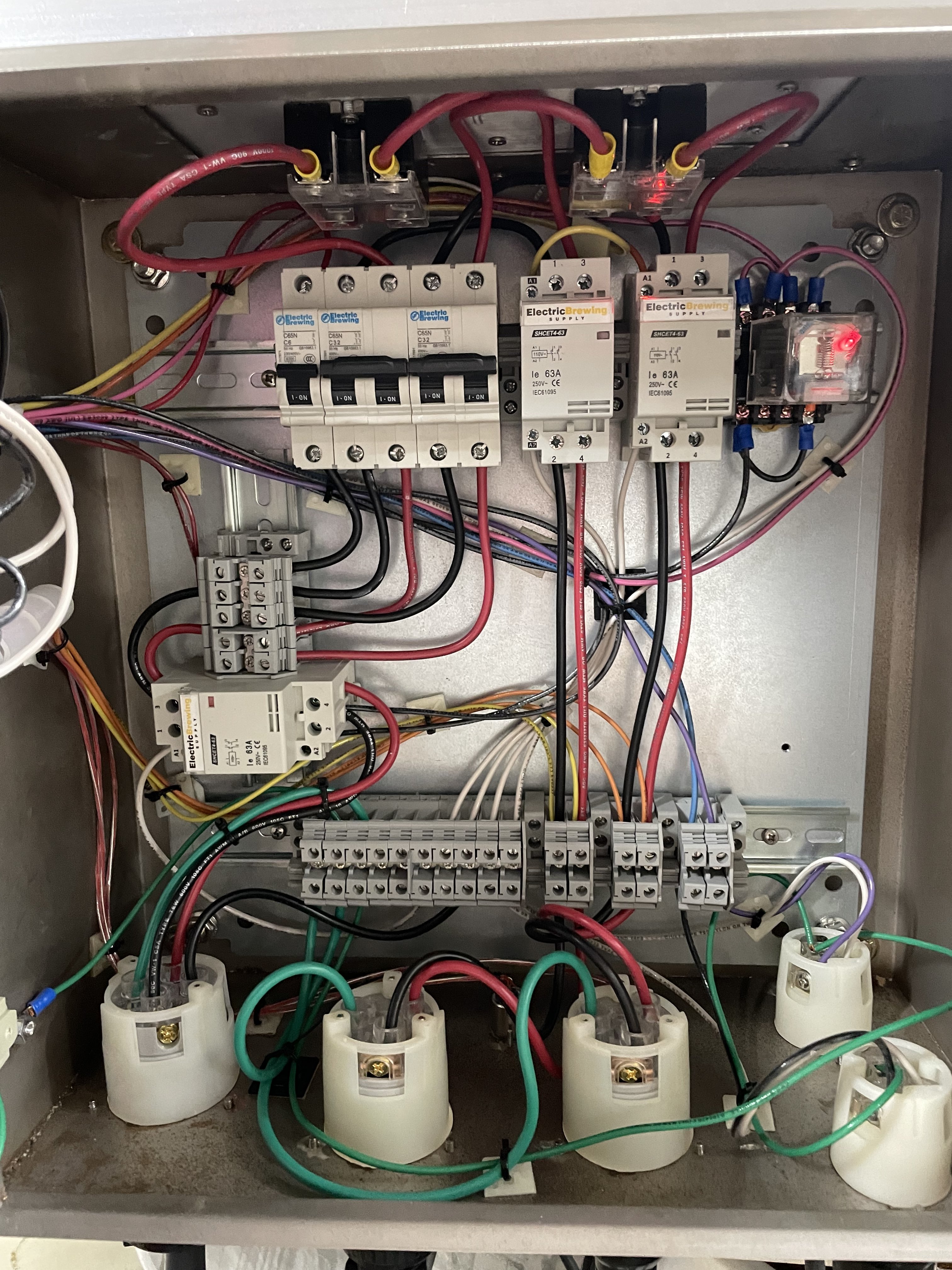
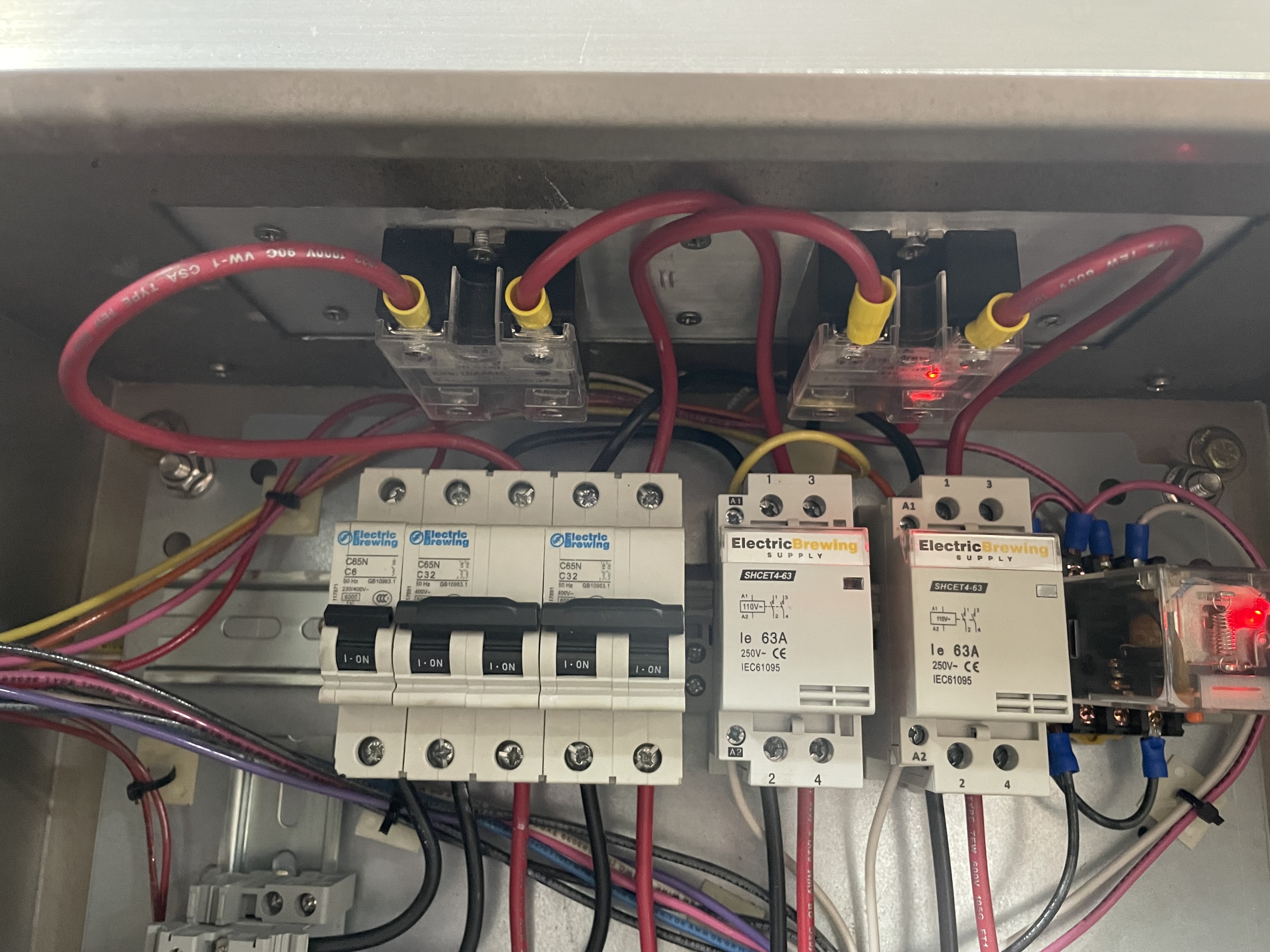
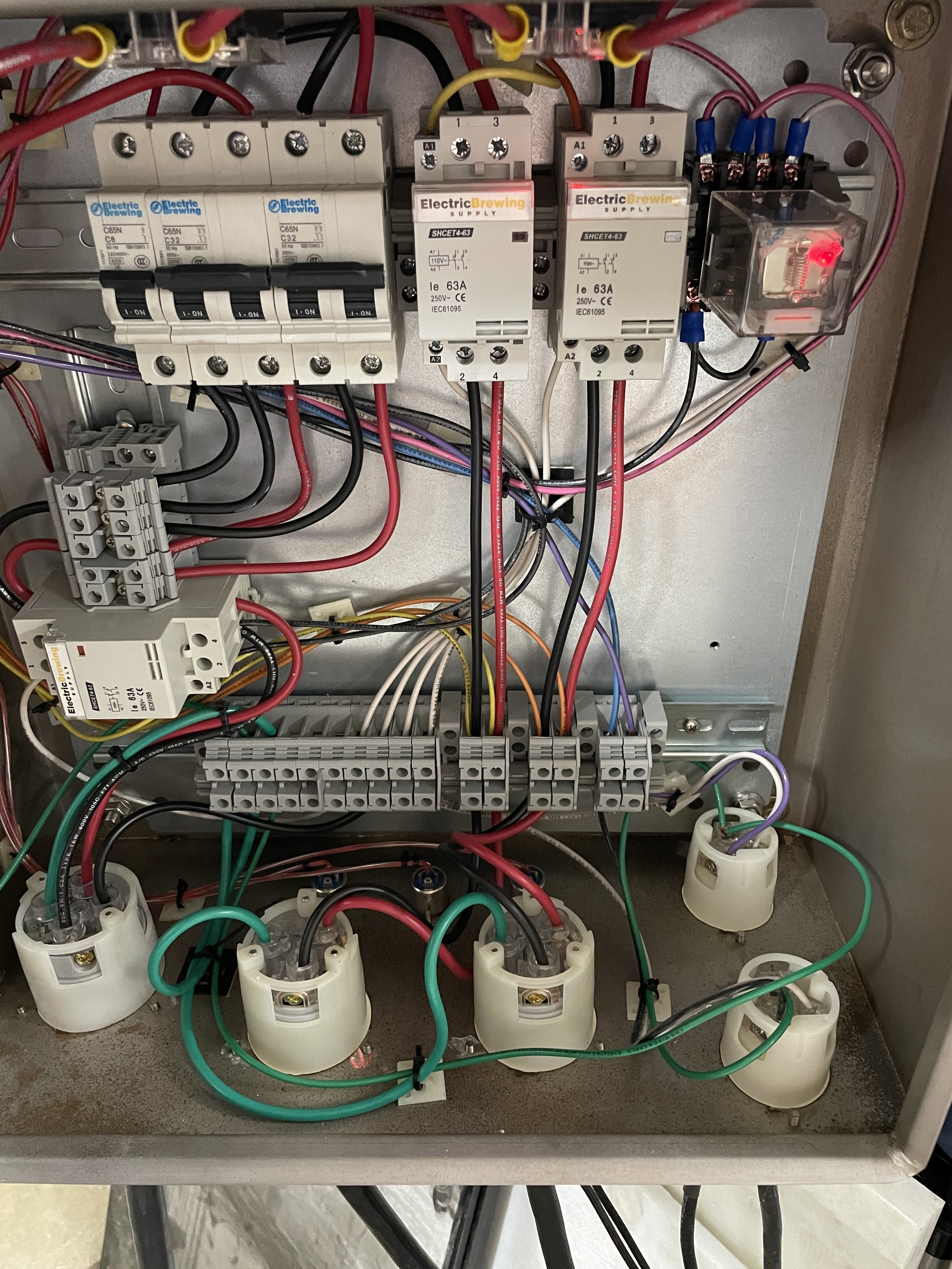
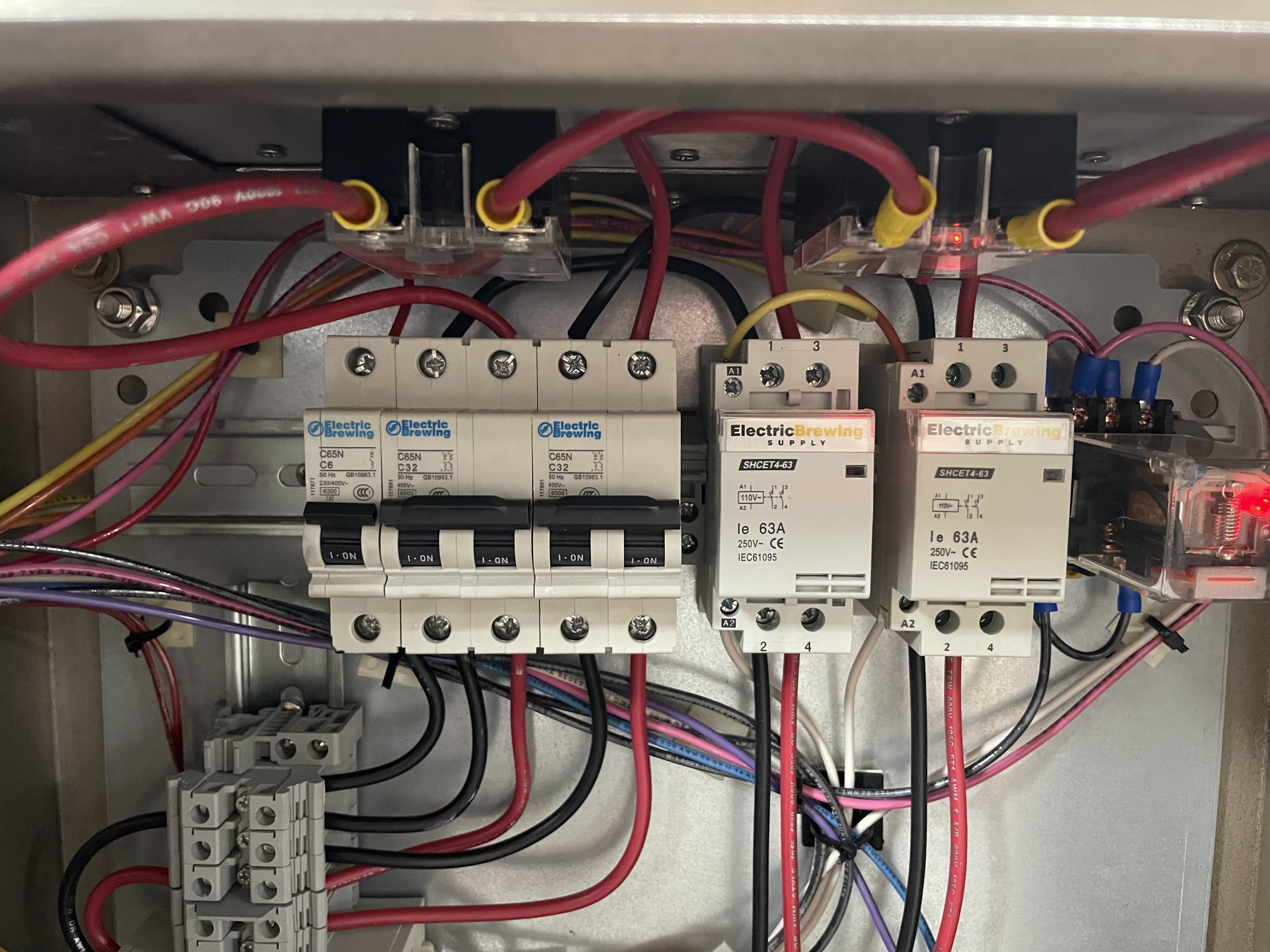
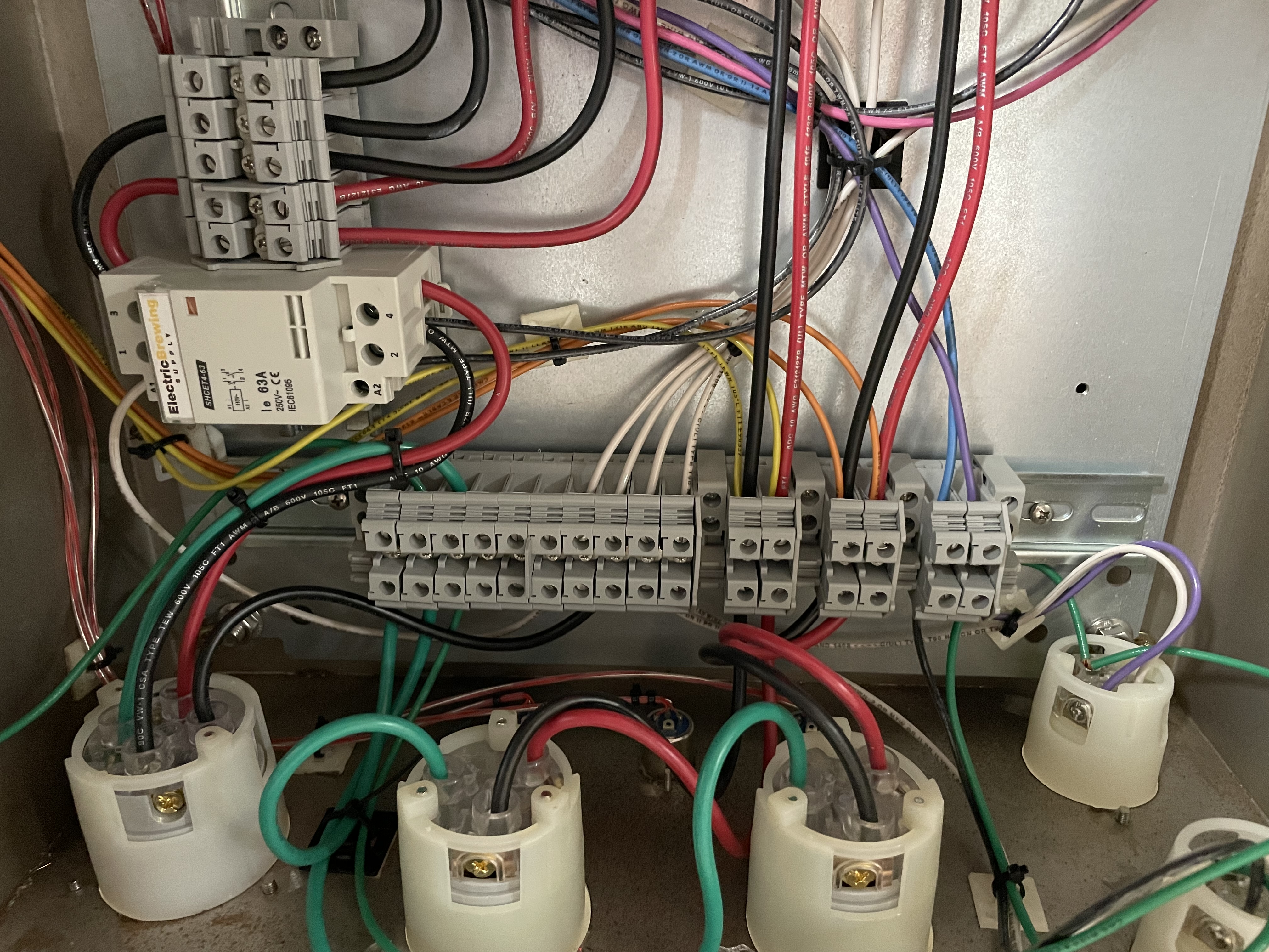
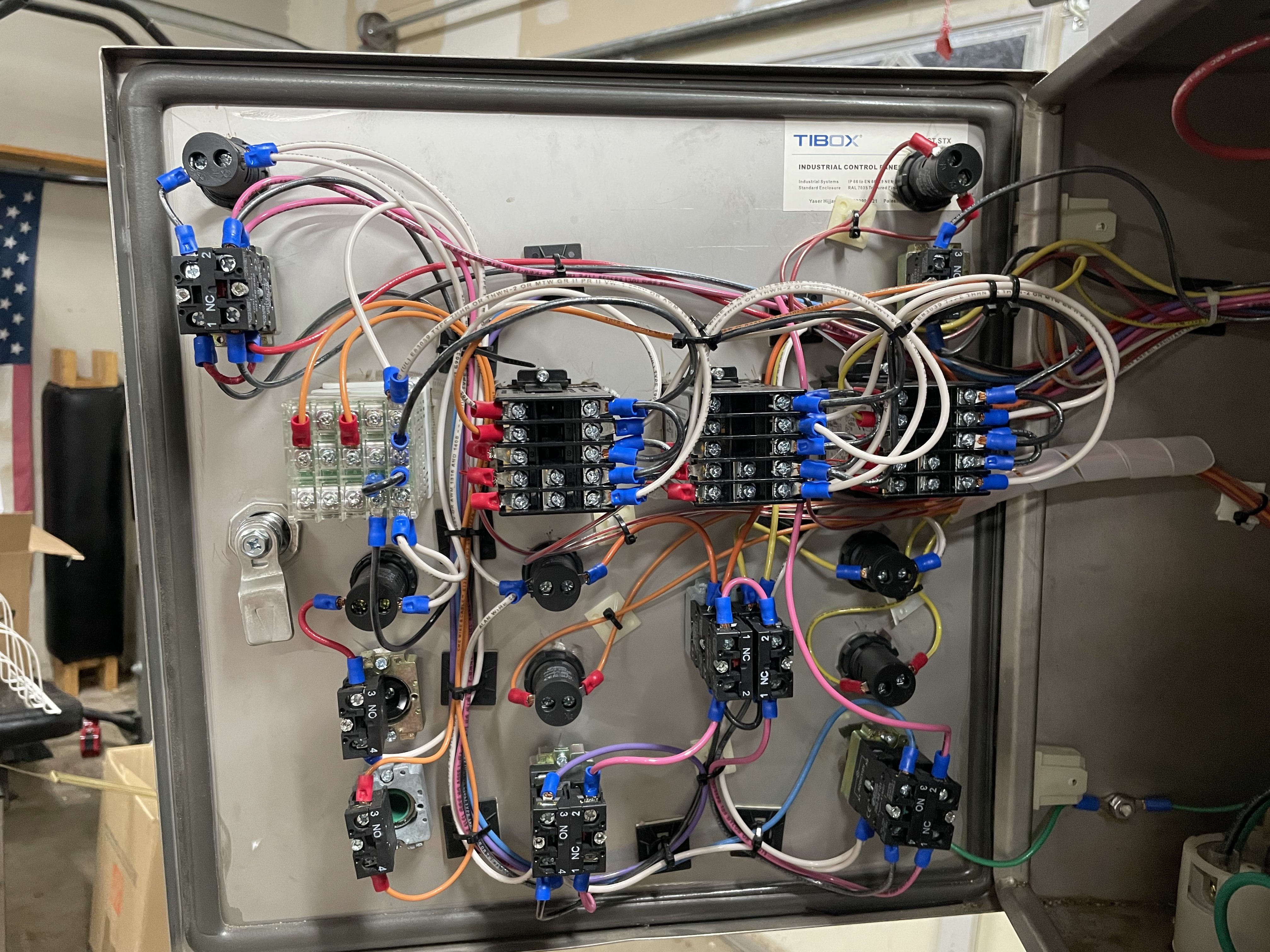
Time for a bunch of detailed pictures of the inside of your control panel from multiple angles, so we can try to figure out what's wired to what.

Brew on :mug:
 
Time for a bunch of detailed pictures of the inside of your control panel from multiple angles, so we can try to figure out what's wired to what.

Brew on :mug:
B5E872CE-3589-47E5-B933-08ABD0F7CE72.jpeg
7D41C1D0-0E98-4D98-AC57-66329E6FDDF7.jpeg
DAA3E917-0225-4D83-9272-B4F3793D998B.jpeg
E754B72D-F8D6-4A1A-9001-6B6837BE17FB.jpeg
AF840183-420C-4EC6-8EC2-080DE088B858.jpeg
5A656814-6772-40E4-B593-5D3719CFED7C.jpeg
2349F70B-5CF5-4CF4-83B3-81EE79BAAFA3.jpeg
71A01E0B-2C1D-4B72-8A8D-701B62013EC8.jpeg

436D6A60-4B83-44CA-A4D5-31E153E81423.jpeg

37AC31F6-5FCE-4B26-A658-2910A96E32CE.jpeg

From what I can tell, the main 240v comes in and goes to the main panel relay switch. From there it splits into three breakers; 120v breaker for all door accessories (controllers, pumps, alarm, etc), 240v two pole for the HLT and a 240v two pole for the boil kettle. From there, one leg of each 240v go into the corresponding kettle relay switches which then go directly to the element outlets. The other leg goes directly to the #1 outlet post on the SSR. #2 outlet post on the SSR then goes into the corresponding kettle relays which then go into the element outlet.

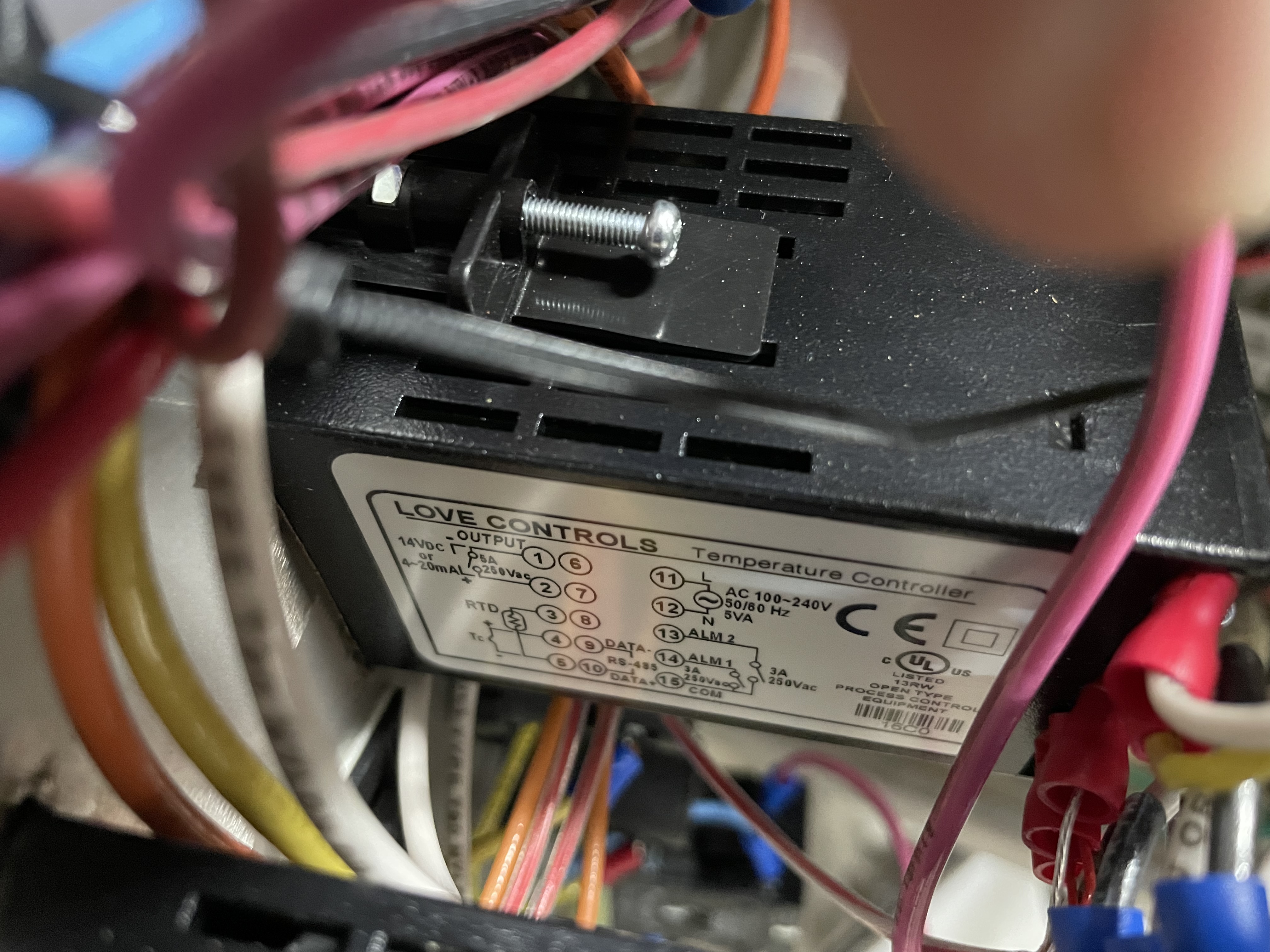
As for the controller wiring, there is an orange wiring running from post 2 on the controller to the #4 post on the SSR. I have tested signal from the controller to the SSR. When the controller calls for heat, I am getting 13v between post 3 and 4.

My current thoughts are 1) bad SSR’s 2) the leg running from the breaker to the SSR should run through the relay switch first and then into the SSR. Then it would run directly from the SSR to the element outlet. I don’t see how option 2 would change much as the current should still be controlled by the SSR.

Please let me know if I can detail anything else here. I’m trying to be as thorough as possible, but I’m sure I’m missing something. Thank you so much for being willing to help me out with this!
 
Schematics would help a lot, but if you don't have any you may need to create one by tracing wires and drawing one up.

The SSR's are easy enough to test. If you pull the lead for the firing input of the SSR (sometimes called the coil) and leave the output (240vAC) connected you would remove the PID control. With the load connected, the output voltage on the load (heating element) would be zero. Don't be confused by the input voltage on the contact side of the SSR as it will always be present with the control system energized.

By separating the PID output from the SSR input you will be isolating the problem. If the voltage remains on the load, the SSR's have failed. You can verify this with an ohmmeter across the output contacts of the SSR, although the ohmmeter won't always show a failure if the fault only occurs in a higher voltage condition.

I would strongly suggest either finding an electrician, instrumentation technician or an engineer to give you a hand with this and trade them some beer for their time. It's likely a simply problem, but it can get confusing trouble shooting this over a forum.

I have designed and built several of these types of systems and they are relatively simple. But some if you have never worked on one it can be daunting.
So just removed the PID inputs and am still getting full voltage to the element. I finally swapped my boil element and temp probe over to the hlt controller and realized that unit is actually working as it is supposed to. I have a new SSR on order and am pretty sure that should solve the issues I’m having. I’ll be sure to report back once I’ve got it installed and do a test.
 
So just removed the PID inputs and am still getting full voltage to the element. I finally swapped my boil element and temp probe over to the hlt controller and realized that unit is actually working as it is supposed to. I have a new SSR on order and am pretty sure that should solve the issues I’m having. I’ll be sure to report back once I’ve got it installed and do a test.
If it does fix it, the next thing to figure is why did it fail. When the SSR's are sized correctly for both voltage and current, they are extremely reliable.
 
If it does fix it, the next thing to figure is why did it fail. When the SSR's are sized correctly for both voltage and current, they are extremely reliable.
I would change your last sentence to: " When quality SSRs are sized correctly for both voltage and current, and properly heatsinked, they are extremely reliable.

OP's panel has a huge heatsink, and looks like thermal grease has been properly applied, so I doubt there is an overheating issue.

It has been well documented that some low cost generic SSRs (particularly counterfeit Fotek's) are built with inadequately rated components. For example IIRC, 25A SSRs have been found with 10A rated TRIACs used for the switching element.

Brew on :mug:
 
low cost generic SSRs
HBT posts seem to confirm that SSR failure isn't super rare. Aside from a history of electrical abuse (e.g. shorting, or over-current load) or thermal problems, I wonder what causes failure in properly built SSRs

fwiw, my $25 SSR (brand?) bought in 2007 is going strong after 185 brew days.
 
I would change your last sentence to: " When quality SSRs are sized correctly for both voltage and current, and properly heatsinked, they are extremely reliable.

OP's panel has a huge heatsink, and looks like thermal grease has been properly applied, so I doubt there is an overheating issue.

It has been well documented that some low cost generic SSRs (particularly counterfeit Fotek's) are built with inadequately rated components. For example IIRC, 25A SSRs have been found with 10A rated TRIACs used for the switching element.

Brew on :mug:
Good point. The SSR's are not a very good place to be stingy. I like to size them at least double the required current. A 5500 watt (240Vac-23 amp) element should be driven by a 50 amp SSR. The voltage is less concerning as long as it 280Vac or higher. The heat sink should be sized so the junction on the SSR does not exceed 140-150F in temperature and proper heat compound applied to the back of the SSR.

I have used Crydom 2450 SSR's in a system with twelve 5500 watt heaters in them. It's been brewing several times a week without any problems for 8 years. The SSR should be beefy enough trip the breaker in a fault without having any damage to it. The 2450 has MTBF of 7 million hours when operated at 60C (140F).

Yeah it might cost a few bucks more, but it really sucks to have to do a repair or worse, interrupt and ruin a brew day.
 
Back
Top