I’m still not following. I’m not a user of iSpindel, I only play with them on the bench so far. Don’t you have to do a 90 deg calibration (laying flat)? Wouldn’t that turn the unit off oriented as you’ve shown?
You are using an out of date browser. It may not display this or other websites correctly.
You should upgrade or use an alternative browser.
You should upgrade or use an alternative browser.
iSpindle - DIY Electronic Hydrometer
- Thread starter LBussy
- Start date

Help Support Homebrew Talk:
This site may earn a commission from merchant affiliate
links, including eBay, Amazon, and others.
I thought about it some more ... If you used the tilt switch (or mercury switch) oriented at a 15° angle or so, it would survive high-gravity and 90° calibration, and still turn off when inverted. Maybe this is exactly what some of you meant but I was confused so it's possible others are as well:

I would think some sort of hysteresis would need to be introduced however to avoid rapid power-cycling from vibration or movement. A capacitor in parallel with the switch (maybe @day_trippr would suggest one?) would reduce the "bounce".
I like this idea!

I would think some sort of hysteresis would need to be introduced however to avoid rapid power-cycling from vibration or movement. A capacitor in parallel with the switch (maybe @day_trippr would suggest one?) would reduce the "bounce".
I like this idea!
BreeBrew
Well-Known Member
So why would you want to use a switch like a tilt switch anyway? Is that so you don't have to open the tube if you have installed a wireless charging receiver? As I understand it, the cap has to come of anyway to sanitize it because dregs collects between the cap and the tube.
Switch that I used: https://nl.aliexpress.com/item/10Pc...195.html?spm=a2g0s.9042311.0.0.27424c4dLXgBb4
Switch that I used: https://nl.aliexpress.com/item/10Pc...195.html?spm=a2g0s.9042311.0.0.27424c4dLXgBb4
One may use a washer between the lid and the tube (like Tilt) to eliminate the need to remove the lid. It also allows assurance that anything sitting on it's cap on your brew shelf is not draining the battery and won't be dead when you need it.
I’m still not following. I’m not a user of iSpindel, I only play with them on the bench so far. Don’t you have to do a 90 deg calibration (laying flat)? Wouldn’t that turn the unit off oriented as you’ve shown?
When I calibrated ours I used the recommended 20° off vertical in 1.000sg. I've checked my calibration data and the largest angle from vertical was 73° in 1.090.
I thought about it some more ... If you used the tilt switch (or mercury switch) oriented at a 15° angle or so, it would survive high-gravity and 90° calibration, and still turn off when inverted. Maybe this is exactly what some of you meant but I was confused so it's possible others are as well:
View attachment 630008
I would think some sort of hysteresis would need to be introduced however to avoid rapid power-cycling from vibration or movement. A capacitor in parallel with the switch (maybe @day_trippr would suggest one?) would reduce the "bounce".
I like this idea!
This is essentially what I alluded to.
So why would you want to use a switch like a tilt switch anyway? Is that so you don't have to open the tube if you have installed a wireless charging receiver? As I understand it, the cap has to come of anyway to sanitize it because dregs collects between the cap and the tube.
I think wireless charging is the main goal. I agree that it still needs to be cleaned, but perhaps there is a way for someone.
One may use a washer between the lid and the tube (like Tilt) to eliminate the need to remove the lid. It also allows assurance that anything sitting on it's cap on your brew shelf is not draining the battery and won't be dead when you need it.
A silicon washer is a good idea. I think wireless charging would be interesting because every time I charge it, the calibration is off and I have to re-calculate the formula based on the angle at 1.000sg and the angle it displays at O.G. and derive from those 2 numbers. This isn't ideal, but is good enough for my purposes.
In all honesty, I'm not that interested in the tilt switch for myself. But, I'd be willing to incorporate it for those that are. I'm also willing to put in some R & D since I have some credit over at pcbs.io thanks to all that have ordered the board. I'll just need a little help spec'ing out the parts.
BreeBrew
Well-Known Member
I think wireless charging would be interesting because every time I charge it, the calibration is off and I have to re-calculate the formula based on the angle at 1.000sg and the angle it displays at O.G. and derive from those 2 numbers. This isn't ideal, but is good enough for my purposes.
The calibration is off because the hardware isn't fixed within the tube? I am thinking of fixate it within the tube by pooring a bit of epoxy on the bottom, but that seems a little to drastic. I would like to hear other suggestions.
The PCB I fixed within the drawer by using a couple of drops of Bondic(https://notaglue.com/), so that is fixed but the drawer itself isn't fixed.
But to calibrate it every time using the two values you mentioned looks like a good idea. I was looking for a more easier way of calibrating the thing, I also don't need the exact SG during fermentation, I just want to see if fermentation is on the way or if it is ready, temp and voltage is nice to have. At the end of fermentation I will measure it anyway using the hydrometer or refractometer.
Erik.

$44.99
$49.95
Craft A Brew - Mead Making Kit – Reusable Make Your Own Mead Kit – Yields 1 Gallon of Mead
Craft a Brew

$176.97
1pc Commercial Keg Manifold 2" Tri Clamp,Ball Lock Tapping Head,Pressure Gauge/Adjustable PRV for Kegging,Fermentation Control
hanhanbaihuoxiaoshoudian

$76.92 ($2,179.04 / Ounce)
Brewing accessories 1.5" Tri Clamp to Ball Lock Post Liquid Gas Homebrew Kegging Fermentation Parts Brewer Hardware SUS304 Brewing accessories(Gas Hose Barb)
chuhanhandianzishangwu

$7.79 ($7.79 / Count)
Craft A Brew - LalBrew Voss™ - Kveik Ale Yeast - For Craft Lagers - Ingredients for Home Brewing - Beer Making Supplies - (1 Pack)
Craft a Brew
![Craft A Brew - Safale S-04 Dry Yeast - Fermentis - English Ale Dry Yeast - For English and American Ales and Hard Apple Ciders - Ingredients for Home Brewing - Beer Making Supplies - [1 Pack]](https://m.media-amazon.com/images/I/41fVGNh6JfL._SL500_.jpg)
$6.95 ($17.38 / Ounce)
$7.47 ($18.68 / Ounce)
Craft A Brew - Safale S-04 Dry Yeast - Fermentis - English Ale Dry Yeast - For English and American Ales and Hard Apple Ciders - Ingredients for Home Brewing - Beer Making Supplies - [1 Pack]
Hobby Homebrew

$33.99 ($17.00 / Count)
$41.99 ($21.00 / Count)
2 Pack 1 Gallon Large Fermentation Jars with 3 Airlocks and 2 SCREW Lids(100% Airtight Heavy Duty Lid w Silicone) - Wide Mouth Glass Jars w Scale Mark - Pickle Jars for Sauerkraut, Sourdough Starter
Qianfenie Direct

$53.24
1pc Hose Barb/MFL 1.5" Tri Clamp to Ball Lock Post Liquid Gas Homebrew Kegging Fermentation Parts Brewer Hardware SUS304(Liquid Hose Barb)
yunchengshiyanhuqucuichendianzishangwuyouxiangongsi

$20.94
$29.99
The Brew Your Own Big Book of Clone Recipes: Featuring 300 Homebrew Recipes from Your Favorite Breweries
Amazon.com

$719.00
$799.00
EdgeStar KC2000TWIN Full Size Dual Tap Kegerator & Draft Beer Dispenser - Black
Amazon.com

$22.00 ($623.23 / Ounce)
AMZLMPKNTW Ball Lock Sample Faucet 30cm Reinforced Silicone Hose Secondary Fermentation Homebrew Kegging joyful
无为中南商贸有限公司

$49.95 ($0.08 / Fl Oz)
$52.99 ($0.08 / Fl Oz)
Brewer's Best - 1073 - Home Brew Beer Ingredient Kit (5 gallon), (Blueberry Honey Ale) Golden
Amazon.com

$53.24
1pc Hose Barb/MFL 1.5" Tri Clamp to Ball Lock Post Liquid Gas Homebrew Kegging Fermentation Parts Brewer Hardware SUS304(Gas MFL)
Guangshui Weilu You Trading Co., Ltd

$479.00
$559.00
EdgeStar KC1000SS Craft Brew Kegerator for 1/6 Barrel and Cornelius Kegs
Amazon.com

$58.16
HUIZHUGS Brewing Equipment Keg Ball Lock Faucet 30cm Reinforced Silicone Hose Secondary Fermentation Homebrew Kegging Brewing Equipment
xiangshuizhenzhanglingfengshop
The calibration is off because the hardware isn't fixed within the tube? I am thinking of fixate it within the tube by pooring a bit of epoxy on the bottom, but that seems a little to drastic. I would like to hear other suggestions.
Correct. Epoxying the sled in the tube is a good solution to fix the calibration from shifting, however it might cause a problem if you ever want (or need) to replace the battery. But I suppose you could just replace the entire tube, sled, and battery at that point. If you epoxy the PCB to the sled, you'll have to replace that too.
... I also don't need the exact SG during fermentation, I just want to see if fermentation is on the way or if it is ready, temp and voltage is nice to have. At the end of fermentation I will measure it anyway using the hydrometer or refractometer.
Erik.
This is precisely how I use it.
BreeBrew
Well-Known Member
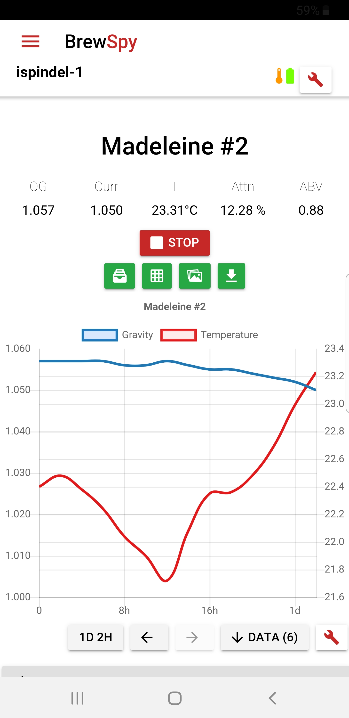
It's working great! Brewed a Belgian wit yesterday and threw the ispindel in the bucket. I only used the 90 degree offset, the measured max SG from the sugar solution and the OG of this brew to calculate the Plato formula. So far so good.
Last edited:
shambolic94
Member
Looking for any troubleshooting ideas on my mostly-built iSpindel, which I cannot get to accept the firmware via NodeMCU flasher.
My build followed the perfboard approach (as shown here: https://www.hobbybrouwen.nl/forum/index.php?topic=33743.0). Pics below. I used the BAT43 diode in place of the 470ohm resistor. I removed the wemos diode by pulling it off with tweezers but left on the LEDs on the gyroscope and Wemos (for now) so I could tell when it is on. The battery seems to charge fine and when I switch it on with the Wemos plugged into my (windows 10) PC, NodeMCU flasher recognizes a new COM port. When I try to flash the firmware (I've tried the latest version and a few earlier ones) the Wemos's blue LED starts flashing, but nothing happens in the software. Just an endless rotating blue circle in the bottom left corner and "Waiting MAC."
I've tried several different USB cords for the Wemos and also checked my soldering as best I can without removing the charger from the perfboard. I specifically tried to make sure I hadn't inadvertently bridged any adjacent soldering points (thus the scuffed up areas of the board). I've also tried it with and without external power from a USB port. I've also uninstalled and reinstalled the CH340 driver. I've tried various baud rates and flash speeds (though probably not every possible combination). The flash location I've used is 0x00000.
I did make an earlier mistake in that I tried numerous times to flash the Wemos before I hooked up the battery, using just the current from the USB to the charger. It wouldn't even recognize the COM port when I tried that approach, and I later learned the battery was essential for flashing. I'm wondering if those prior battery-less attempts somehow damaged the Wemos? I've already ordered a new Wemos from China just in case, but wondering if there's any other troubleshooting I can try while I wait a month for it arrive?
Any ideas would be greatly appreciated.
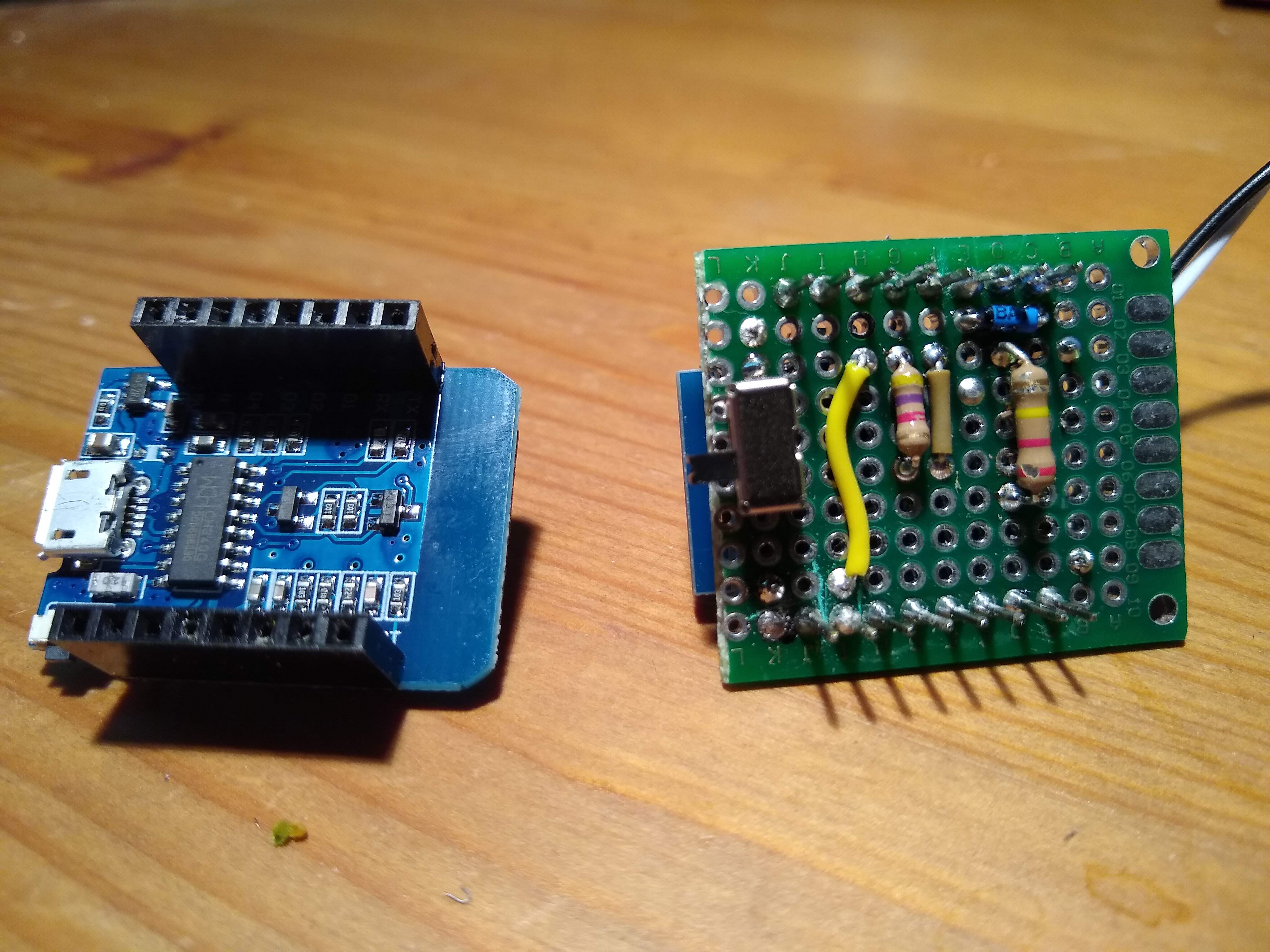
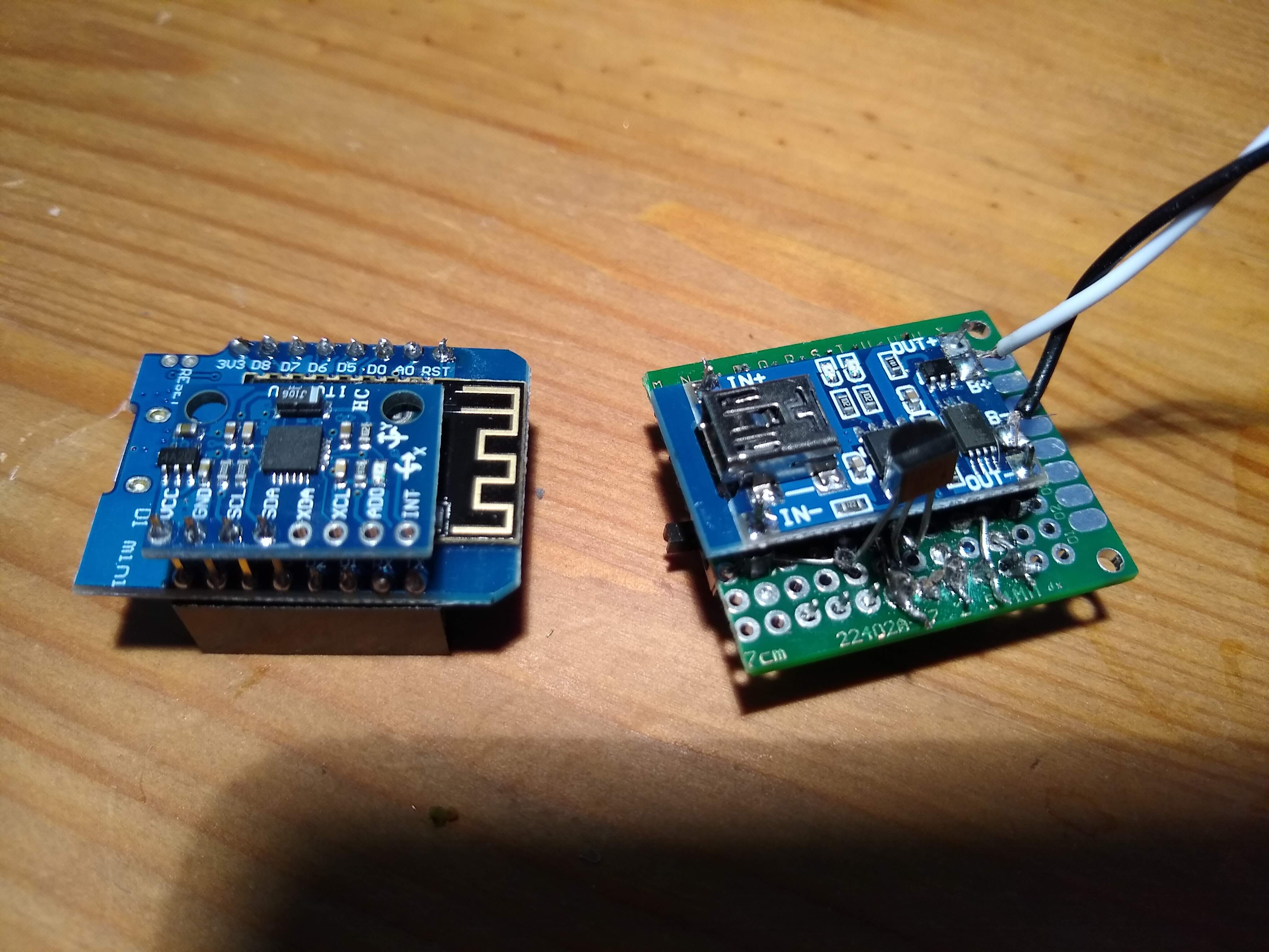


Stand
Well-Known Member
Bluetooth D1 Mini? Hmmm. I wonder how compatible is this with existing architecture? I think there are smaller versions of that chip as well
https://www.aliexpress.com/item/For...82-484a-ba34-fe53b95cabd2&transAbTest=ae803_3
https://www.aliexpress.com/item/For...82-484a-ba34-fe53b95cabd2&transAbTest=ae803_3
shambolic94
Member
I didn't buy a bluetooth wemos on purpose, but I definitely could have done so by accident. How can you tell it's bluetooth?
BreeBrew
Well-Known Member
Did you follow the instructions on https://github.com/universam1/iSpindel/blob/master/docs/Firmware_en.md
Because it nowhere states that the battery has to be hooked on. When you hook up the wemos to it's own usb port it should be powered by that.
Other than that, are you in the Netherlands? Because I have enough of the special Ispindel PCB's and could hook you up with one for your newly ordered d1 mini. PM me if you want one.

Stand
Well-Known Member
I flashed mine before I soldered in case something went wrong.
Battery isn't necessary to flash.
I have made 2 of these with d1 v3, and I had to use earlier versions to flash them over serial and then flashed with the latest version from the wifi configuration screen... or is it maintenance? Anyway that worked for me to get it flashed.
Battery isn't necessary to flash.
I have made 2 of these with d1 v3, and I had to use earlier versions to flash them over serial and then flashed with the latest version from the wifi configuration screen... or is it maintenance? Anyway that worked for me to get it flashed.
shambolic94
Member
I think the battery may be necessary once you remove the diode from the Wemos. At any rate, my Wemos does not work at all when plugged into my PC without the battery connected. And when I tried plugging it in while connected to the USB-powered charger, but no battery attached, it kind of went haywire--repeatedly connecting and disconnecting and ultimately crashing my PC. Now that the battery's attached, I at least get a stable COM port connection. I just can't flash.
Following Stand's suggestion, I did try to flash an earlier version of the firmware (5.1.2) and had the same problem.
I think when the new Wemos arrives I will try flashing it before removing the diode and attaching to the battery. Maybe I'll have better luck that way. If not, maybe I'll go the PCB route, as BreeBrew suggests. It wouldn't shock me if I screwed up the soldering somehow -- it was pretty tricky, especially the connections around the temp sensor.
BreeBrew
Well-Known Member
I indeed didn't remove the diode from the wemos. Infact I didn't remove anything. I just have to remember that when I want to flash over USB for some reason I have to disconnect the battery otherwise it will get 5V and I could set the house on fire. But after initial flash I flash over wifi now.
Is the BAT43 in the right direction on your board? Cathode to DO?
Is the BAT43 in the right direction on your board? Cathode to DO?
shambolic94
Member
Thanks, yes, I was careful to correctly orient the BAT43 after seeing others having problems because of that. It's visible in the top pic I posted above, with the end with the black band connected to the pin that goes to D0.
Stand
Well-Known Member
I went PCB. Really happy with it. If you go this route you only need to remove diode from gyro, and no silly sled.I think the battery may be necessary once you remove the diode from the Wemos. At any rate, my Wemos does not work at all when plugged into my PC without the battery connected. And when I tried plugging it in while connected to the USB-powered charger, but no battery attached, it kind of went haywire--repeatedly connecting and disconnecting and ultimately crashing my PC. Now that the battery's attached, I at least get a stable COM port connection. I just can't flash.
Following Stand's suggestion, I did try to flash an earlier version of the firmware (5.1.2) and had the same problem.
I think when the new Wemos arrives I will try flashing it before removing the diode and attaching to the battery. Maybe I'll have better luck that way. If not, maybe I'll go the PCB route, as BreeBrew suggests. It wouldn't shock me if I screwed up the soldering somehow -- it was pretty tricky, especially the connections around the temp sensor.
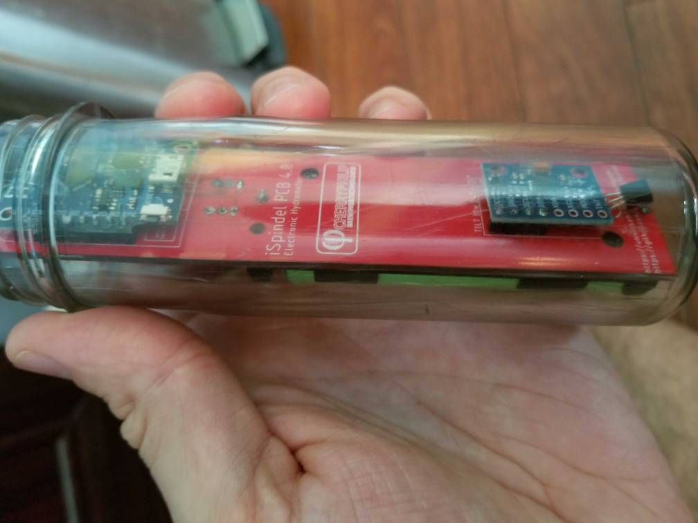
BreeBrew
Well-Known Member
Yeah well, got myself 26 of these so they have to be used firstDid you follow....
View attachment 631357
Just came across this fellow on AliExpress:

TTGO WiFi & Bluetooth Battery ESP32 Module ESP32 0.96 inch OLED development tool For Arduino - $8.52
I don't know exactly how big the large petlings are, but this would be an interesting board to adapt to the project. Battery is there, OLED could be used for setup/validation, charging, even BLE. The price is rather high, but if it could fit a petling as-is, that's a lot less work.
Just morning musings ....
Stand
Well-Known Member
Well, it would also be an issue of porting the code to the ESP32 (semi-trivial) and then the fun of actually adding functionality for the OLED and BLE. More than an weekend of work I'm sure. Still, would be cool.I feel like someone tried awhile back and gave up. I think it is a size issue.
Post #900 and 905 @shoo looked into doing this but gave up and went with the PCB
It really would streamline things.
I'm sure there's a vial somewhere which would work.
Stand
Well-Known Member
Would be neat. I still wonder about those bluetooth versions because they would allow you to shrink everything down to something closer to a tilt.
I know exactly zero about programming though, and I dunno that it would be worth anyone's while when it already works really well.
I know exactly zero about programming though, and I dunno that it would be worth anyone's while when it already works really well.
The problem is, Samuel's license is rather restrictive. So you can fork it for your own use but not redistribute it (sort of hard to prevent someone from cloning your fork though.) That means that if someone goes to all the trouble to port it to ESP32, add OLED and BLE, it's done for their own use only.
Then of course there's the issue where it begins to infringe upon the Tilt patent ... which is a mess nobody wants.
Then of course there's the issue where it begins to infringe upon the Tilt patent ... which is a mess nobody wants.
I plan on pulling one of these together soon... Currently waiting on a few parts to arrive. I have been thinking about the sled. I don't have a 3d printer and don't have access to one locally. I was wondering if anyone has made a sled out of wood or foam. Are there any CAD files for the printed sleds I can grab dimensions off of; I know each plastic cylinder is different but it would be a good starting point.
Thanks everyone for your help!
MT
Thanks everyone for your help!
MT
BreeBrew
Well-Known Member
Upload the stl files of the sled to https://www.3dhubs.com/manufacture/I plan on pulling one of these together soon... Currently waiting on a few parts to arrive. I have been thinking about the sled. I don't have a 3d printer and don't have access to one locally. I was wondering if anyone has made a sled out of wood or foam. Are there any CAD files for the printed sleds I can grab dimensions off of; I know each plastic cylinder is different but it would be a good starting point.
Thanks everyone for your help!
MT
When you have, you get an on screen visualization of it and you can see the dimensions there.
shoo
Well-Known Member
- Joined
- Aug 14, 2017
- Messages
- 93
- Reaction score
- 28
Just came across this fellow on AliExpress:
View attachment 631864
TTGO WiFi & Bluetooth Battery ESP32 Module ESP32 0.96 inch OLED development tool For Arduino - $8.52
I don't know exactly how big the large petlings are, but this would be an interesting board to adapt to the project. Battery is there, OLED could be used for setup/validation, charging, even BLE. The price is rather high, but if it could fit a petling as-is, that's a lot less work.
Just morning musings ....
Yeah, I gave up on that approach. It seems like it would work in theory, but it turns out to be pretty inconvenient (ignoring my quality control woes). The side-mounted USB and power switch makes it difficult to charge/program/turn off, and would likely require recalibrating on every use since you need to take it out of the tube to charge.
Thanks BreeBrew I will check it out!Upload the stl files of the sled to https://www.3dhubs.com/manufacture/
When you have, you get an on screen visualization of it and you can see the dimensions there.
BreeBrew
Well-Known Member
My latest addition to nu iSpindel, wireless charging. I used this one:
€ 1,72 26%OFF | FONKEN USB Draadloze Opladen Ontvanger Universele Android Micro USB Type-C Qi Draadloze Oplader Lading Pad Module voor Mobiele telefoon
https://s.click.aliexpress.com/e/4zMrJ61nH
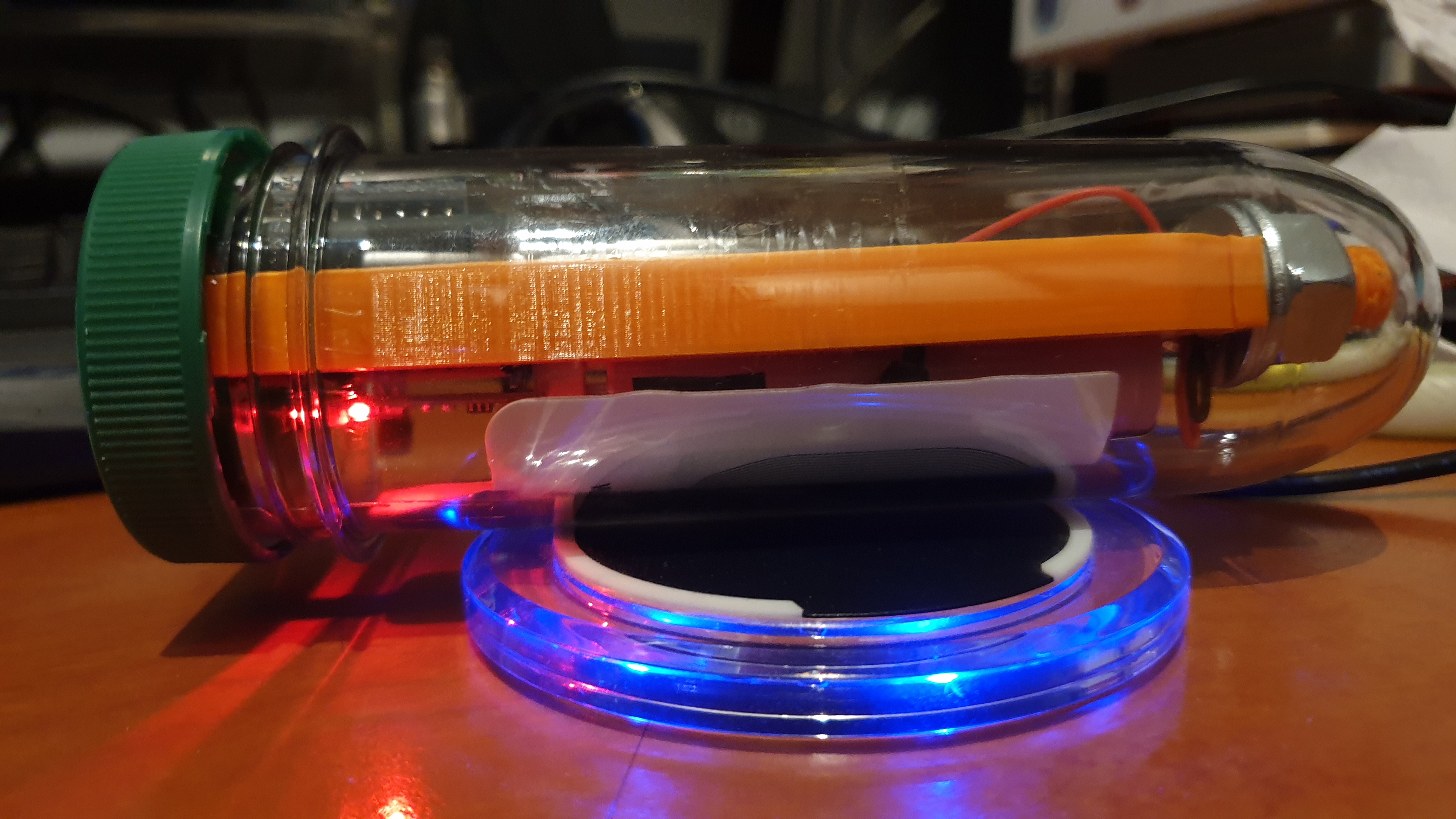
€ 1,72 26%OFF | FONKEN USB Draadloze Opladen Ontvanger Universele Android Micro USB Type-C Qi Draadloze Oplader Lading Pad Module voor Mobiele telefoon
https://s.click.aliexpress.com/e/4zMrJ61nH

BreeBrew
Well-Known Member
And I took it off allready. It became way to hot to my liking. I mean hot like almost not touchable. And because it was on top of the battery I don't want to take any chances.My latest addition to nu iSpindel, wireless charging. I used this one:
€ 1,72 26%OFF | FONKEN USB Draadloze Opladen Ontvanger Universele Android Micro USB Type-C Qi Draadloze Oplader Lading Pad Module voor Mobiele telefoon
https://s.click.aliexpress.com/e/4zMrJ61nH
View attachment 633160
Well that's too bad. An internal switch, a better seal, and wireless charging would be a nice combo.
Bigdaddyale
Well-Known Member
what version of the PCB did you use?I went PCB. Really happy with it. If you go this route you only need to remove diode from gyro, and no silly sled.View attachment 631478
Stand
Well-Known Member
4.0 the earlier versions aren't compatible with the newer and safer battery charging units.
https://www.pcbway.com/project/shareproject/iSpndel_4_0.html
https://www.pcbway.com/project/shareproject/iSpndel_4_0.html
Who owns that design? Would love to get the Eagle/Gerber files.
Stand
Well-Known Member
I just found this from the guy that made the PCBs. I thought it would be helpful to drop it here.
Bigdaddyale
Well-Known Member
Whoops- link already posted
Yeah unless I'm missing something, you can't download the files there. Can't seem to find contact information for that person.
I'm all about throwing a bone to the guy who took the time to create the board (folks often get credits at the fab house when you order them) but 1) I don't want to order from that place and 2) I'd like to make some changes. I suppose I could just make one from scratch, but it's nice to start from something that's been tested to work.
I'm all about throwing a bone to the guy who took the time to create the board (folks often get credits at the fab house when you order them) but 1) I don't want to order from that place and 2) I'd like to make some changes. I suppose I could just make one from scratch, but it's nice to start from something that's been tested to work.
Bigdaddyale
Well-Known Member
The guys name is Filippo here is his Github page https://github.com/cherryphilip74/iSpindel-PCBYeah unless I'm missing something, you can't download the files there. Can't seem to find contact information for that person.
I'm all about throwing a bone to the guy who took the time to create the board (folks often get credits at the fab house when you order them) but 1) I don't want to order from that place and 2) I'd like to make some changes. I suppose I could just make one from scratch, but it's nice to start from something that's been tested to work.
Oh awesome, thank you sir!
BreeBrew
Well-Known Member
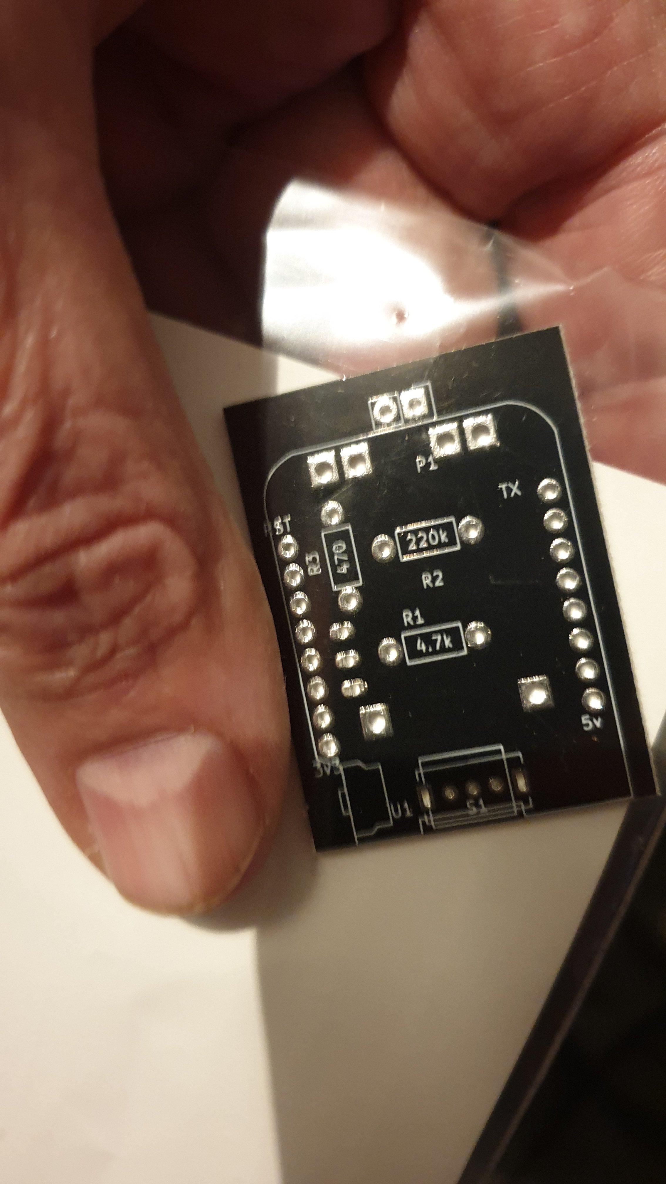
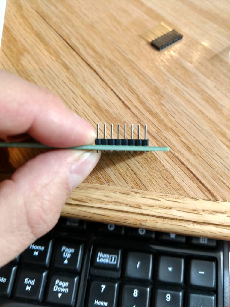
I am waiting on one more part but I am going to start soldering up the PCB. What orientation should I solder the header to the board and is the black spacer piece needed? The top part of the PCB (where my pointer finger is) will have the wemos and the accelerometer. Thanks for your help.
MT

MT


Similar threads
- Replies
- 33
- Views
- 8K
- Replies
- 3
- Views
- 1K


