EyeofdaHawk
Well-Known Member
Thanks Mike
Have hooked it up like that. Not just have to connected the alarm and it's done.
Cheers
Hawk
Have hooked it up like that. Not just have to connected the alarm and it's done.
Cheers
Hawk

Hi Hawk,
Connect the donut to the other 2 points and pass the red wire, going from the main contactor to the SSR, thru the donut.
I hope that helps!
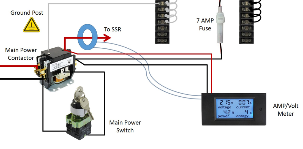

Hey Mike, by passing only the RED leg of power through the CT, that will only give you the AMPS of the heating elements and not the whole draw of the system, correct?
If you wanted to see ALL of the voltage and AMPs that my control panel is using, I would pass BOTH the RED & Black power supply power through the ct? I'm assuming so? Would that be correct?
Like this?View attachment 556342
No, you don't want to run both wires thru the current detection coil. If you run both thru in the "normal" direction, then the currents will subtract from each other, and the only current measured will be the imbalance between the red and black wires at the location of the coil. If you run one of the wires in the reverse direction, then the currents will add, and you will read roughly twice the element current (plus the red/black current imbalance.) Just so happens I did a design yesterday that shows how to measure the total element, pump, and electronics current. Note that in this design everything but the pump is running on 240V. If you want to make sure you measure all of the 120V (as well as 240V) current, then all of the 120V must be taken from one and only one of the hot lines (the black hot in the case of the schematic below.)Yes, only the red cable and it will show you the amp draw of the elements. That's the only important thing anyway as the amp draw from the pumps is not significant.
If you want to pass both wires thru the donut, I think you need to invert the direction of one wire. Like running one wire from one side thru the donut and the 2nd from the other side. Just try it, you won't break anything. Worst case, your reading is incorrect.
Let me know if that worked...
When your element is set to 100% power, the amp meter should show about 22 amp's (if your elements are 5500W).


No, you don't want to run both wires thru the current detection coil. If you run both thru in the "normal" direction, then the currents will subtract from each other, and the only current measured will be the imbalance between the red and black wires at the location of the coil. If you run one of the wires in the reverse direction, then the currents will add, and you will read roughly twice the element current (plus the red/black current imbalance.) Just so happens I did a design yesterday that shows how to measure the total element, pump, and electronics current. Note that in this design everything but the pump is running on 240V. If you want to make sure you measure all of the 120V (as well as 240V) current, then all of the 120V must be taken from one and only one of the hot lines (the black hot in the case of the schematic below.)
")


Thanks Mike, and Thanks Doug, for clearing that up for me.
I see how in Mike's system, why the CT is placed where it's placed and how it would only read the AMPs/VOLTs of just the elements, IE: after the Main Contactor, before the SSR's.
I figured if the CT was placed on the supply source BEFORE the main contactor [as in your diagram Doug] the CT will read ALL the VOLT/AMPs that the system uses. But I was wrong with putting both hot wires through the CT.
My panel is 50 AMP, with each SSR on it's own circuit. So I think the way I have the power distributed, I would need 2 Volt/Amp meters.
Anyway, I'm assuming again Doug, I could put the CT on either the Red or Black hot wire. or does it have to be on the Black?
If you want to measure the current used by each element, then you need two meters. If you just want to measure the total system current, then a placement like I used will work with a single meter.
The coil doesn't care what color the wire is, only how much current flows thru the wire (and it must be AC current.) Current flows thru loops, and each load is part of a single loop (in normal systems.) However, many wires in the system will be part of multiple loops. The current measured will depend on what combination of loops the particular length of wire belongs to. I'll put together a little drawing to help explain this.
Brew on
Thank you again Doug, You are the man!If you want to measure the current used by each element, then you need two meters. If you just want to measure the total system current, then a placement like I used will work with a single meter.
The coil doesn't care what color the wire is, only how much current flows thru the wire (and it must be AC current.) Current flows thru loops, and each load is part of a single loop (in normal systems.) However, many wires in the system will be part of multiple loops. The current measured will depend on what combination of loops the particular length of wire belongs to. I'll put together a little drawing to help explain this.
Brew on

Most of the alarm "outputs" on all PID's, timers, etc. are in reality just single pole single throw switches (relays.) Although in some cases they are single pole double throw. They do not provide any power unless you wire power to one (or the other) of a pair alarm terminals. Like most switches, it does not mater which side is connected to power, and which side goes to the load, except in the case of double throw relays, where it's usually the common terminal that gets connected to power.Hi again, sorry this is an addtional question. I'm trying to figure out how to wire int he alarm, from 2 Ezboil, (120 and 320) and a SYL. Alarm wiring appears to be both 1+2 and 13+14. I'm not using a timer, and so will go straight to the alarm and alarm off switch. Can i just wire up the DSPRs and SYL in parallel and wire the Ezboil 120 (closest to alarm/switch) to the alarm/switch, similar to your design? I'm just confused where it all has to go (from which Ezboil/SYL connector).
This literally is the last bit. After this i rewire the garage (to handle the ampage) and hey presto, brewery operational (provided it all works).
Thanks
Hawk
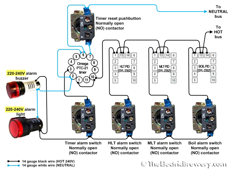
Thats because its the basic (economy ) model... The 320 has the additional bells and whistles such as the multiple relays for alarms and such.. I used mine to start an auxiliary timer for my hop additions once the boil was reached.Oh actually for some reason my DSPR120 does not have connecorts 13+14...
Okay, so I just received all my components to finish building my kegs and I will be done this weekend. I’m looking into ordering the parts for the control panel. I’m going to need a power cable for the control. Do I need to order other components to support this? How would I go about wiring this up? I’m not an electrician so any detailed how to, will be appreciated.
PLEASE HELP!!!!
I purchased the copy already but like I said I’m no electrician. I’m going to attempt to build the control panel. I rather try and build it than purchase one. I want that feeling of accomplishment! [emoji16] just point me to the right direction.
By the way, it’s a great write up!
just a heads up, If you dont know this already I think your violating the forum rules and may get in trouble here for promoting the sale of your products without being a forum vendor or sponsor...Please have a look here. Should become handy...
just a heads up, If you dont know this already I think your violating the forum rules and may get in trouble here for promoting the sale of your products without being a forum vendor or sponsor...
Lowe's and home Depot... Carlon 12x12x8 I believe.. like 38-40 bucksWe're are you guys finding these 12x12x6 boxes. The ones im finding are in the $80 range
Try to find a distributor for electrical supplies. That’s where the electricians buy their stuff. There should be one near you.We're are you guys finding these 12x12x6 boxes. The ones im finding are in the $80 range
Thanks guys. I have been to both my local Home Depot and lowes and no boxes. No 30a spa box either just 50a.
One more question for now lol
For the 8 circuit terminal strip is 600v 25a what I'm looking for? It's the only one I seem to find that has a plastic cover over the terminals.


![Craft A Brew - Safale BE-256 Yeast - Fermentis - Belgian Ale Dry Yeast - For Belgian & Strong Ales - Ingredients for Home Brewing - Beer Making Supplies - [3 Pack]](https://m.media-amazon.com/images/I/51bcKEwQmWL._SL500_.jpg)


