EyeofdaHawk
Well-Known Member
Oh actually for some reason my DSPR120 does not have connecorts 13+14...

Most of the alarm "outputs" on all PID's, timers, etc. are in reality just single pole single throw switches (relays.) Although in some cases they are single pole double throw. They do not provide any power unless you wire power to one (or the other) of a pair alarm terminals. Like most switches, it does not mater which side is connected to power, and which side goes to the load, except in the case of double throw relays, where it's usually the common terminal that gets connected to power.Hi again, sorry this is an addtional question. I'm trying to figure out how to wire int he alarm, from 2 Ezboil, (120 and 320) and a SYL. Alarm wiring appears to be both 1+2 and 13+14. I'm not using a timer, and so will go straight to the alarm and alarm off switch. Can i just wire up the DSPRs and SYL in parallel and wire the Ezboil 120 (closest to alarm/switch) to the alarm/switch, similar to your design? I'm just confused where it all has to go (from which Ezboil/SYL connector).
This literally is the last bit. After this i rewire the garage (to handle the ampage) and hey presto, brewery operational (provided it all works).
Thanks
Hawk

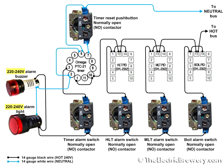
Thats because its the basic (economy ) model... The 320 has the additional bells and whistles such as the multiple relays for alarms and such.. I used mine to start an auxiliary timer for my hop additions once the boil was reached.Oh actually for some reason my DSPR120 does not have connecorts 13+14...


![Craft A Brew - Safale S-04 Dry Yeast - Fermentis - English Ale Dry Yeast - For English and American Ales and Hard Apple Ciders - Ingredients for Home Brewing - Beer Making Supplies - [1 Pack]](https://m.media-amazon.com/images/I/41fVGNh6JfL._SL500_.jpg)


Okay, so I just received all my components to finish building my kegs and I will be done this weekend. I’m looking into ordering the parts for the control panel. I’m going to need a power cable for the control. Do I need to order other components to support this? How would I go about wiring this up? I’m not an electrician so any detailed how to, will be appreciated.
PLEASE HELP!!!!
I purchased the copy already but like I said I’m no electrician. I’m going to attempt to build the control panel. I rather try and build it than purchase one. I want that feeling of accomplishment! [emoji16] just point me to the right direction.
By the way, it’s a great write up!
just a heads up, If you dont know this already I think your violating the forum rules and may get in trouble here for promoting the sale of your products without being a forum vendor or sponsor...Please have a look here. Should become handy...
just a heads up, If you dont know this already I think your violating the forum rules and may get in trouble here for promoting the sale of your products without being a forum vendor or sponsor...
Lowe's and home Depot... Carlon 12x12x8 I believe.. like 38-40 bucksWe're are you guys finding these 12x12x6 boxes. The ones im finding are in the $80 range
Try to find a distributor for electrical supplies. That’s where the electricians buy their stuff. There should be one near you.We're are you guys finding these 12x12x6 boxes. The ones im finding are in the $80 range
Thanks guys. I have been to both my local Home Depot and lowes and no boxes. No 30a spa box either just 50a.
One more question for now lol
For the 8 circuit terminal strip is 600v 25a what I'm looking for? It's the only one I seem to find that has a plastic cover over the terminals.
")
Yes correct its the same enclosure many suppliers like high gravity and now brua supply have been using for years... Its designed to be a watertight electrical box.That looks like plastic
Yes correct its the same enclosure many suppliers like high gravity and now brua supply have been using for years... Its designed to be a watertight electrical box.
Much easier to cut the holes in than steel as well.
Do you not trust your wiring or components in a plastic electrical box? its the same stuff the pids, switches, ssrs and contactors are all made of as well as many other more complicated electronic devices like stereo, printer, tvs, projectors, coffee makers ... well pretty much any appliance these days.
In all my years here I havent seen one issue with a plastic enclosure yet.
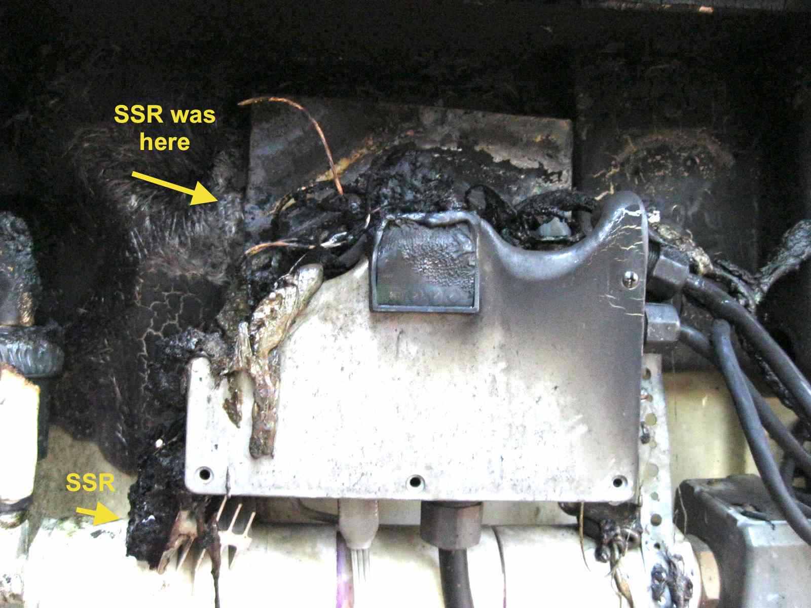
I would think, niether would a properly built and gfci protected box. Good grief was there anyone even around to let that go that long?Better spending 15 minutes on cutting metal. A metal box would never melt like that.
I would think, niether would a properly built and gfci protected box. Good grief was there anyone even around to let that go that long?
So I'm going to necro this thread with a question..
That way you are controlling your heat source for your mash based directly on the mash temps.
Is there some reason not to do this? Or is the temperature differential between HLT and the mash in a HERMS system just too small for that to matter?
In my opinion, and that's what I do, controlling the mash temp by heating the HLT and controlling the temperature inside the HLT to my target mash temp is safer. If you heat it to a couple degrees more, and send (for example) 170F wort back in the mash, you might kill off the enzymes. It might be too slow for step mash though, I'm only doing single mash temp so I don't know.
From my experience, I set my HLT to target mash temp and monitor the mash temp with another pid that controls nothing (really, it's just there to see the temperature of the mash) and everything stays within 0.5F of target.
Sorry I was busy yesterday and didn't get a chance to respond. @guillaume is doing things correctly. Here's why:So I'm going to necro this thread with a question.. @doug293cz you might be able to answer this better than anyone
Wouldn't a better design be:
Install a switch that changes which PID controls the heating element in the HLT. So during Strike/Sparge it's controlled by the HLT PID, but during mash its controlled by the Mash PID.
That way you are controlling your heat source for your mash based directly on the mash temps.
Is there some reason not to do this? Or is the temperature differential between HLT and the mash in a HERMS system just too small for that to matter?
I just don't want to end up in a situation where I'm guestimating how many degrees higher I need to set my HLT PID to get my mash temp where I want it for every brew.
Sorry I was busy yesterday and didn't get a chance to respond. @guillaume is doing things correctly. Here's why:
If you try to use a mash temp probe to control the HLT temp, you have a long time lag between when the mash temp responds to the higher HLT temp. The effect of the time lag is to allow the HLT water to heat up way beyond the MLT target temp before the PID shuts down heating to the HLT. This then results in overheating the MLT while the HLT cools back down. If you let this system run for a long time, you tend to get wide oscillations in temp that have a period of many minutes to hours. To get around this, you have to slow down the response of the PID+heater to the point where the time lag in temp response is a fraction of the heat up time of the PID+heater. Then you get extremely slow response if you want to change temps. As guillaume noted, the wort in the HEX could get hot enough to denature the enzymes when the HLT overheats.
You could add an over temp shutoff to the HLT heater, that would be set a few degrees above the mash temp, but then the system will act just like an HLT temp probe controlled system with the HLT temp set a couple of degrees hotter than the MLT target.
If you really want a fast heat up response in a HERMS system, without significant overshoot, you would need to use a non-PID algorithm that used two temp probes, and accounted for the lag time in the system. A really good algorithm could continuously measure the response time and adjust the algorithm parameters to compensate in real time. The algo would also limit max HLT temp to minimize denaturing. There is an algorithm something like this in the BrewPi control software, but IDK if it handles the max HLT temp limit requirement.
Brew on
.jpg")
Yes, controlling with a probe in the mash stream returning from the HEX will certainly reduce the time lag responding to increases in HLT temp, and eliminate the possibility of overheating the wort. It would be interesting to see the temp deltas between in HLT and in mash return probes. I suspect that the deltas would be a fraction of the deltas between HLT and bulk mash, and wonder if there is any significant difference in control between the HLT and stream placements.In my opinion, the simplest way to control your mash temp with a herms is to put the "controlling" temp probe at the top of the mash tun and put the "monitoring" temp probe at the mash tun drain. Thus, you control the temp of wort as it returns to the top of the mash and monitor the temp of the wort as it leaves the bottom of the mash. To me, this is the most direct way of controlling mash temp. Controlling with the temp probe in the mash leads to the issues with lag times and overshoot and controlling with the temp probe in the HLT requires extrapolation of mash temps from HLT temps.
View attachment 616219


