If you have a USB to TTL converter, it might be interesting to reset that while connected to a terminal session and see if any weird characters are sent when it resets.
You are using an out of date browser. It may not display this or other websites correctly.
You should upgrade or use an alternative browser.
You should upgrade or use an alternative browser.
How To: BrewPi LCD Add-On
- Thread starter day_trippr
- Start date

Help Support Homebrew Talk:
This site may earn a commission from merchant affiliate
links, including eBay, Amazon, and others.
Car Ramrod
Well-Known Member
- Joined
- Jan 24, 2019
- Messages
- 117
- Reaction score
- 16
Yes I have one. So reset the hc05 and the adruino.
I was incredibly unclear, sorry about that.
What I meant was: Connect the HC-05 to your USB to TTL converter and get it connected to a terminal session and talking properly. Then do "stuff" to it to see if you can make it act weird. Reset it, pull the power, on/off/on/off/on rapid cycles, etc. See if it spits out any jibberish to the screen.
If for instance it spits out an "E", "S" or "C", it's gonna wipe out settings on the Arduino.
Is it time? It might be time. Time for something new in the world of BrewPi Arduino. Thanks to @CadiBrewer for putting up with my crazy ideas, a new shield is born!
This is v1.3, code named: "The One Shield." I can't see where we can do anything different with the Arduino Uno. Perhaps most significantly, this shield provides hardware support for an I2C display (there's important information about this below). There are other improvements which I think you guys are gonna dig.
BrewPi Arduino Uno Shield v1.3 (I2C/RevC) Changelog:
Here's some PCB porn:


I have not yet uploaded the Eagle files to the BrewPi Remix website, but if you want to get a jump on things, get some board quickly (but maybe for a few extra bucks); I've uploaded the files to OshPark (hence the purple board.) The BOM is there as well, including a link to a BOM on Mouser which contains most of the parts needed.
This board should rightfully be considered an Alpha release, since none exist in the wild yet. Three people have reviewed the design however, and it builds on a successful predecessor for the more complicated circuits. I have the boards on order, should be assembling next weekend. I was way too excited not to share in this thread, however. As soon as they are tested, I'll make a release post on the Mega Thread.
As with most things related to electronics on this project, a HUGE thanks to @day_trippr for his original design, his assistance which was given to @CadiBrewer for versions 1.1 and 1.2, and for answering my stupid questions finalizing v1.3.
This is v1.3, code named: "The One Shield." I can't see where we can do anything different with the Arduino Uno. Perhaps most significantly, this shield provides hardware support for an I2C display (there's important information about this below). There are other improvements which I think you guys are gonna dig.
BrewPi Arduino Uno Shield v1.3 (I2C/RevC) Changelog:
- (NEW) Four-pin I2C header. No more having to use that 16-pin ribbon! A mere 4 wires to connect your display. (Yes, the previous parallel LCD is supported as well.)
- (NEW) Rotary encoder header - No more having to figure out which Arduino header pins to use! There's also a rotary encoder breakout (thanks @gromitdj!) to make that easier to wire up.
- (CHANGE) LED headers - The old headers were one pin each for heat and cool, connected to a pull-up resistor. That worked fine with "normal" setups, but the wiring was not straightforward for what I call "mere mortals." And, if you used non-inverted outputs for heat and cool (such as with SRs) you found yourself in a strange position. These headers are three-pin: VCC <-> D5/6 <-> GND. This means if you are using "normal" inverted outputs, you connect your LEDs to VCC and the center pin for either LED. If you are using non-inverted outputs, you connect the LEDs to GND and the center pin for either LED.
- (CHANGE) Relays: This change re-orders the pins to match the typical relay headers.
- (NEW) OneWire Selection: One each three-pin header to switch between A0 or A4 for the One-Wire bus. You must use A0 if you are using I2C. Not sure why Elco ever used A4 but that's one of the hard-wired I2C pins for the Arduino so a chance was necessary.
- (CHANGE) Power: Version 1.2 split the power for the LCD and used the ICSP header to power the LCD backlight to reduce LCD scrambling. By all accounts that had no impact. On some Arduino clones (as well as the combo ESP8266/ATmega328P boards) have the ICSP header in a different place, which ended up requiring jumpers to apply power to the LCD, and/or creating a shorting point with the pins hitting an unexpected place on the controller board. This has been re-combined with the power and ground points looped together to form a single larger bus. In addition, from v0.2.11 of the Arduino firmware, there is a timer which resets the LCD display every 180 seconds to get rid of any scrambling.
- (NEW) Break-Out Board support: An RJ45 to allow for a remote break-out board. This uses an Ethernet cable (which is straight-through) as opposed to the smaller RJ11 (telephone cord) because phone cords are cross-over by default. The pin-out supports @Thorrak's original breakout boards, however support for remotely placing the heat/cool relays is also included. A breakout board supporting all of this is in development:
- Pin 1 - Unused
- Pin 2 - Unused
- Pin 3 - VCC
- Pin 4 - OneWire Data (A4 or A0)
- Pin 5 - GND
- Pin 6 - Door (D4)
- Pin 7 - Cool (D5)
- Pin 8 - Heat (D6)
- (NEW) Door pins: The original Arduino firmware has support for a contact switch which detects when the door is open. I don't know of many folks using this but adding two pins for that was easy enough since we already put it on the RJ45.
- (NEW) Alarm: The original firmware has VERY basic support for an alarm (piezo speaker). Right now, it only beeps when the Arduino resets but maybe we can do something more with it later.
- (CHANGE) Parallel LCD header: Even though the old header was 16-pins, we only used 12 of them. Using a straight 16 was simpler and kept people form screwing things up too bad but we needed the room. So, the parallel LCD header is now split into two 6-pin headers. This does give the benefit of making this connection much easier to route as bending two 6-wire ribbons is a lot easier than a 16-wire one.
- (NEW) LCD Backlight always-on: If one used the v1.2 board with no rotary encoder or at least a switch, the LCD would time-out and not be able to be turned back on. Added R13 to keep the backlight always-on in those cases. To make use of this functionality, REMOVE R12 and ADD R13.
- I2C support is a separate firmware image and only available in version 0.2.12. As of right now (6/1/19) this is a beta image, but I should be ready to release it soon. Firmware 0.2.12 requires BrewPi Scripts/WWW v0.5.2.1 which is currently in the Devel branch.
- You MUST select "A0" on the One-Wire selector.
Here's some PCB porn:
I have not yet uploaded the Eagle files to the BrewPi Remix website, but if you want to get a jump on things, get some board quickly (but maybe for a few extra bucks); I've uploaded the files to OshPark (hence the purple board.) The BOM is there as well, including a link to a BOM on Mouser which contains most of the parts needed.
This board should rightfully be considered an Alpha release, since none exist in the wild yet. Three people have reviewed the design however, and it builds on a successful predecessor for the more complicated circuits. I have the boards on order, should be assembling next weekend. I was way too excited not to share in this thread, however. As soon as they are tested, I'll make a release post on the Mega Thread.
As with most things related to electronics on this project, a HUGE thanks to @day_trippr for his original design, his assistance which was given to @CadiBrewer for versions 1.1 and 1.2, and for answering my stupid questions finalizing v1.3.
Last edited:
OP
OP
For the record, Lee had a full-nelson grip on this effort 
My contribution was finding one show-stopper bug and then general assurance he was totally on the right track.
Board looks great!
Cheers!
My contribution was finding one show-stopper bug and then general assurance he was totally on the right track.
Board looks great!
Cheers!
CadiBrewer
Well-Known Member
For the record, my contribution was to put everything on the board so Lee could then move everything where he wanted, and then to channel my inner Dave by telling him to beef up the GND and 5V traces.


$53.24
1pc Hose Barb/MFL 1.5" Tri Clamp to Ball Lock Post Liquid Gas Homebrew Kegging Fermentation Parts Brewer Hardware SUS304(Gas MFL)
Guangshui Weilu You Trading Co., Ltd


$22.00 ($623.23 / Ounce)
AMZLMPKNTW Ball Lock Sample Faucet 30cm Reinforced Silicone Hose Secondary Fermentation Homebrew Kegging joyful
无为中南商贸有限公司


$58.16
HUIZHUGS Brewing Equipment Keg Ball Lock Faucet 30cm Reinforced Silicone Hose Secondary Fermentation Homebrew Kegging Brewing Equipment
xiangshuizhenzhanglingfengshop


$53.24
1pc Hose Barb/MFL 1.5" Tri Clamp to Ball Lock Post Liquid Gas Homebrew Kegging Fermentation Parts Brewer Hardware SUS304(Liquid Hose Barb)
yunchengshiyanhuqucuichendianzishangwuyouxiangongsi


![Craft A Brew - Safale S-04 Dry Yeast - Fermentis - English Ale Dry Yeast - For English and American Ales and Hard Apple Ciders - Ingredients for Home Brewing - Beer Making Supplies - [1 Pack]](https://m.media-amazon.com/images/I/41fVGNh6JfL._SL500_.jpg)
$6.95 ($17.38 / Ounce)
$7.47 ($18.68 / Ounce)
Craft A Brew - Safale S-04 Dry Yeast - Fermentis - English Ale Dry Yeast - For English and American Ales and Hard Apple Ciders - Ingredients for Home Brewing - Beer Making Supplies - [1 Pack]
Hobby Homebrew


$719.00
$799.00
EdgeStar KC2000TWIN Full Size Dual Tap Kegerator & Draft Beer Dispenser - Black
Amazon.com

$479.00
$559.00
EdgeStar KC1000SS Craft Brew Kegerator for 1/6 Barrel and Cornelius Kegs
Amazon.com


$33.99 ($17.00 / Count)
$41.99 ($21.00 / Count)
2 Pack 1 Gallon Large Fermentation Jars with 3 Airlocks and 2 SCREW Lids(100% Airtight Heavy Duty Lid w Silicone) - Wide Mouth Glass Jars w Scale Mark - Pickle Jars for Sauerkraut, Sourdough Starter
Qianfenie Direct


$76.92 ($2,179.04 / Ounce)
Brewing accessories 1.5" Tri Clamp to Ball Lock Post Liquid Gas Homebrew Kegging Fermentation Parts Brewer Hardware SUS304 Brewing accessories(Gas Hose Barb)
chuhanhandianzishangwu

$176.97
1pc Commercial Keg Manifold 2" Tri Clamp,Ball Lock Tapping Head,Pressure Gauge/Adjustable PRV for Kegging,Fermentation Control
hanhanbaihuoxiaoshoudian


$44.99
$49.95
Craft A Brew - Mead Making Kit – Reusable Make Your Own Mead Kit – Yields 1 Gallon of Mead
Craft a Brew


$20.94
$29.99
The Brew Your Own Big Book of Clone Recipes: Featuring 300 Homebrew Recipes from Your Favorite Breweries
Amazon.com


$7.79 ($7.79 / Count)
Craft A Brew - LalBrew Voss™ - Kveik Ale Yeast - For Craft Lagers - Ingredients for Home Brewing - Beer Making Supplies - (1 Pack)
Craft a Brew


$49.95 ($0.08 / Fl Oz)
$52.99 ($0.08 / Fl Oz)
Brewer's Best - 1073 - Home Brew Beer Ingredient Kit (5 gallon), (Blueberry Honey Ale) Golden
Amazon.com


Without both of you this would not have happened.

Well, I said it was an alpha ...
No issues with the v1.3 design, as far as I know it works. I did however make a small change that I think will make it easier for folks. Instead of removing R12 and adding R13 if there's no pushbutton/encoder, I added a jumper cap for selection. I thought that would make it more flexible for folks if they change their design around. You no doubt would have some pin strip and a cap laying around anyway so no added cost for the hobbyist.
Updated design here for v1.3.1, all the rest of the notes apply. If you ordered yesterday and logged in just to see this change already ... sorry. If it makes you feel any better I ordered yesterday too.
Car Ramrod
Well-Known Member
- Joined
- Jan 24, 2019
- Messages
- 117
- Reaction score
- 16
Well Lee, I ordered a set of boards and will help you out if you need.
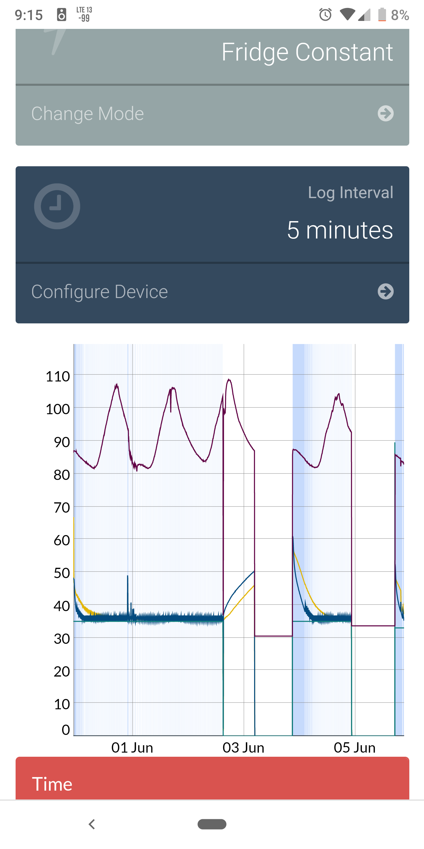
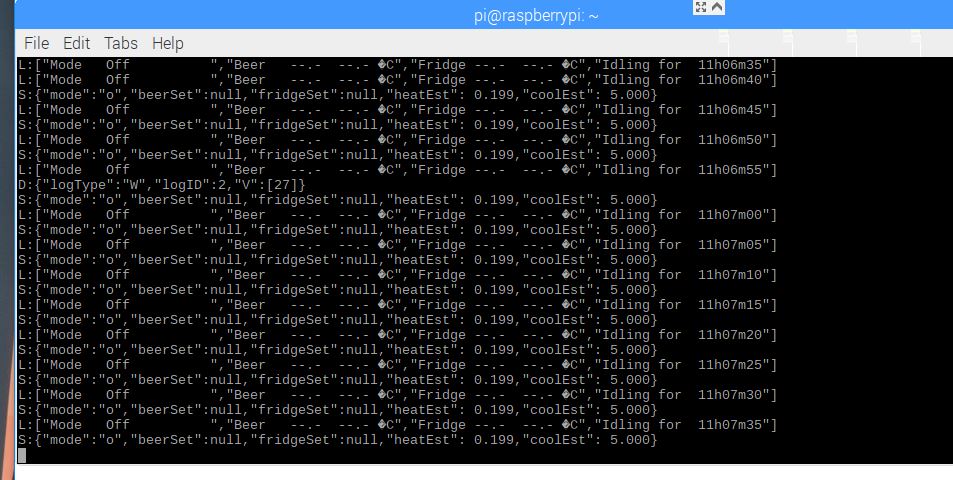
So back to the issue I am having. I set my box up and let it run. About 3 days in it deleted everything again. Fermentrack read the same as the screen, no sensors and celsius. But it still had the correct pins and everything set up in the settings. Once I unassigned one of the probes it unassigned everything and the screen showed fahrenheit. I was able to reset everything and let it run again. It happened again 2 days later. I had logging on so I'm able to show you the graph. Is there a log I can pull out and look at?
Don't mind the ambient temp, lol. I'm in South Louisiana and it has been super hot here and even hotter in the garage.
So I believe you still think it is a Bluetooth issue as I didn't movie the box at all so I doubt it is a shorting issue. I'm not very terminal savvy, so while I understood what you said do to I don't know the exact way to do it.
Also I looked high and low in fermentrack for the "wipe Arduino clean" bit couldn't find it. Should I get brewpi remix up and running to use this feature. Note I am using an non adruino brand Uno.
Attachments
You should be able to use screen or another tool to issue the command if it’s not available in Fermentrack (although I gotta believe it’s there somewhere). I’ll drop you some notes here in a bit when I get to the office.
Car Ramrod
Well-Known Member
- Joined
- Jan 24, 2019
- Messages
- 117
- Reaction score
- 16
Thanks Lee.
Zio, I believe he said he would upload the files soon. Seems like this is early in the development and just olpit it one place so a couple people can get it together and test it before it is widely available.
Zio, I believe he said he would upload the files soon. Seems like this is early in the development and just olpit it one place so a couple people can get it together and test it before it is widely available.
First, install screen:So I believe you still think it is a Bluetooth issue as I didn't movie the box at all so I doubt it is a shorting issue. I'm not very terminal savvy, so while I understood what you said do to I don't know the exact way to do it.
Also I looked high and low in fermentrack for the "wipe Arduino clean" bit couldn't find it. Should I get brewpi remix up and running to use this feature. Note I am using an non adruino brand Uno.
sudo apt install screen
Run the following:
sudo screen /dev/rfcomm0 57600
(assuming your BT device is rfcomm0)
From here you can issue the command "E" which will erase eeprom.
I'll upload the Eagle files as soon as I have the fabrication in my hands to check the first run. In theory that will be tomorrow. I'll assemble on Saturday so by Sunday if things go well. I could export the Gerbers from Eagle, but I have no way of verifying their accuracy after that process so I'd prefer to allow the user to do that/be responsible for it.Any chance you could upload the Gerber files for the latest version please? Costs a lot to order from the US to uk, would rather use a local board supplier to keep costs down.
Car Ramrod
Well-Known Member
- Joined
- Jan 24, 2019
- Messages
- 117
- Reaction score
- 16
Looks like everything cleared. You can/should create your devices again now and see if they stick.
An update on the new boards: I have all my parts and the boards are shipped ... waiting ...
Car Ramrod
Well-Known Member
- Joined
- Jan 24, 2019
- Messages
- 117
- Reaction score
- 16
So it cut out 2 more times this weekend. Im going to hard wire it to confirm if it is the bluetooth module. Then start from scratch with those.
Another board update: I have the 1.3 (not the 1.3.1) boards in my hands. So, if/when I get some time to get up to my office and do some soldering, I have something to solder on. I'm still hoping that the 1.3.1 boards show up soon though.
Added a poll here about the LCD screen scrambles if you all wouldn't mind sharing some info?
matridium
Well-Known Member
- Joined
- Dec 5, 2018
- Messages
- 119
- Reaction score
- 30
I don't get scrambles but occasionally the LCD will go blank for about one second and then back on. Is this normal?Added a poll here about the LCD screen scrambles if you all wouldn't mind sharing some info?
Only happens every once in awhile.
If you have 0.2.11, yes. I have the reset timer in that version. Really trying to figure out though how often it has to fire.I don't get scrambles but occasionally the LCD will go blank for about one second and then back on. Is this normal?
I received the 1.3.1 boards last night. I'll assemble tonight or tomorrow and get some testing done. With any luck I'll get the Eagle files posted this weekend and go ahead and release the supporting code.
Hey guys.
With LBussys help I've managed to get the beta version of BPiRemix installed, and my i2c lcd running on pin A4/5.
Now I have a question about the workings of brewpi...
I got a pi-zero-w with arduino uno. I got two SSR's hooked up to pin 5 and 6 on the positive side, and common ground on the other. Also got temp probes set up and reporting correctly.
I know the SSR's can be controlled, 'cause when I set up things, they will turn on if I don't choose non-inverted.
So far so good - I got brewpi up and running, and want to test it out.
So I go to the lower part of the webinterface, choose f.ex. the fridge constant tab, and punch in something lower than what the probes are reporting - like 7 degrees C, then "apply". The lcd and the webinterface shows "Fridge Const."
In my mind, this should make the controller call for cooling (since the probes report 24 degrees), but it keeps sitting at "idling" - it doesn't seem to start trying to lower the temperature, and the temperature on the right in the display just keeps showing: --.-
Have I misunderstood how it works?
Last edited:
The controller will idle for a time based on a few different things; sometimes it will wait for peak and there's a few other things that will show up when you think it should be flipping a relay. Ultimately, let it sit and it should decide to do something after those timers run out. How long have you let it sit like that?
I'll be able to have a look here in a few ... I have everything torn apart right now.
I'll be able to have a look here in a few ... I have everything torn apart right now.
Found a json error - not sure how I managed to introduce THAT but I believe what you are experiencing is related to that. I'll be able to have a look in a couple hours.
by the way - just throwing something out there - how about a button on the webui, that turns the pi off?
(so I can be lazy and not ssh into it to sudo poweroff)
(or is this already implemented somewhere I didnt look??)
(so I can be lazy and not ssh into it to sudo poweroff)
(or is this already implemented somewhere I didnt look??)
That's been done before - unfortunately that means the www-data user has root access which is A Bad Thing™. I've got another way to do it but it's lower on the list. It is on the issues list on the GitHub so I'm reminded all the time.by the way - just throwing something out there - how about a button on the webui, that turns the pi off?
(so I can be lazy and not ssh into it to sudo poweroff)
(or is this already implemented somewhere I didnt look??)
Bigdaddyale
Well-Known Member
Definitely an issue here somewhere that I was not able to get figured out today. Traveling in the morning so tomorrow night is the soonest I will be able to look at it again. Sorry for the delay. I blame it on the cat - she must have walked over my keyboard.
Quick update for you guys:
I intended to get the new boards tested out over the weekend. A combination of things led to me to get about 90% done with the I2C path and about 80% done with the parallel LCD path. I'm getting the dreaded 85°C reading from the sensors and I've had this issue before with this batch of sensors so I need to buy more. It's probably just the sensors but I don't want to tell you guys it's all tested and find an issue after.
Since posting the boards on OshPark I've moved a couple silk-screen legends to keep them from getting obscured by components, and flipped a trace to get rid of a via. Nothing functional, just stuff I could not leave well enough alone. I'm not going to upload 1.3.1a yet till I get it to 100%.
Last edited:
Quick update for you guys:
I intended to get the new boards tested out over the weekend. A combination of things led to me to get about 90% done with the I2C path and about 80% done with the parallel LCD path. I'm getting the dreaded 85°C reading from the sensors and I've had this issue before with this batch of sensors so I need to buy more. It's probably just the sensors but I don't want to tell you guys it's all tested and find an issue after.
Since posting the boards on OshPark I've moved a couple silk-screen legends to keep them from getting obscured by components, and flipped a trace to get rid of a via. Nothing functional, just stuff I could not leave well enough alone. I'm not going to upload 1.3.1a yet till I get it to 100%.
I've been getting some funky 85 degrees error too with the sensors currently on my breadboard.
I'm not sure it's the sensors though - I just put together a photon "spark" on my breadboard, and it reports temps correctly with the same sensors.
None of the OneWire work has changed .... unless the avr libraries from the vendor changed but that’s a pretty drastic mistake to make. Anything is possible though.
I just know when I go to one sensor it works, then I can add a second, then a third. It’s very weird.
I just know when I go to one sensor it works, then I can add a second, then a third. It’s very weird.
Car Ramrod
Well-Known Member
- Joined
- Jan 24, 2019
- Messages
- 117
- Reaction score
- 16
The BOM is on the OshPark listing.
Car Ramrod
Well-Known Member
- Joined
- Jan 24, 2019
- Messages
- 117
- Reaction score
- 16
I have the BOM and all the pieces, just confirming the resistor and capacitor designation R1,R2,.... Is the same as the other shields.
Oh I got ya. Not necessarily the same, no. I’ll post it here in a few. Just landed. That may have been the worst flight ever.
I updated the description to indicate the resistor/capacitor locations.
Similar threads
- Replies
- 12
- Views
- 4K
- Replies
- 11
- Views
- 2K
