How To: BrewPi LCD Add-On

Homebrew Talk - Beer, Wine, Mead, & Cider Brewing Discussion Forum

Help Support Homebrew Talk - Beer, Wine, Mead, & Cider Brewing Discussion Forum:

This site may earn a commission from merchant affiliate links, including eBay, Amazon, and others.
My company bought me a Metcal dual port station back in aught-seven. I love the thing, it's fabulously capable, but it had a four figure price tag that I'd never spend on myself :D

Looks like this setup, except I have the hot tweezers instead of the desoldering gun, and around 15 tips of all shapes and sizes...

s-l1600.jpg


Cheers!
 
Yeah, I'm sure it works great for the right task but that desoldering gun is like two orders of magnitude too big to be useful in my world. I'm dealing with 0201 passives and the tiniest actives we can lay hands on because there ain't much room on an M.2 card :)

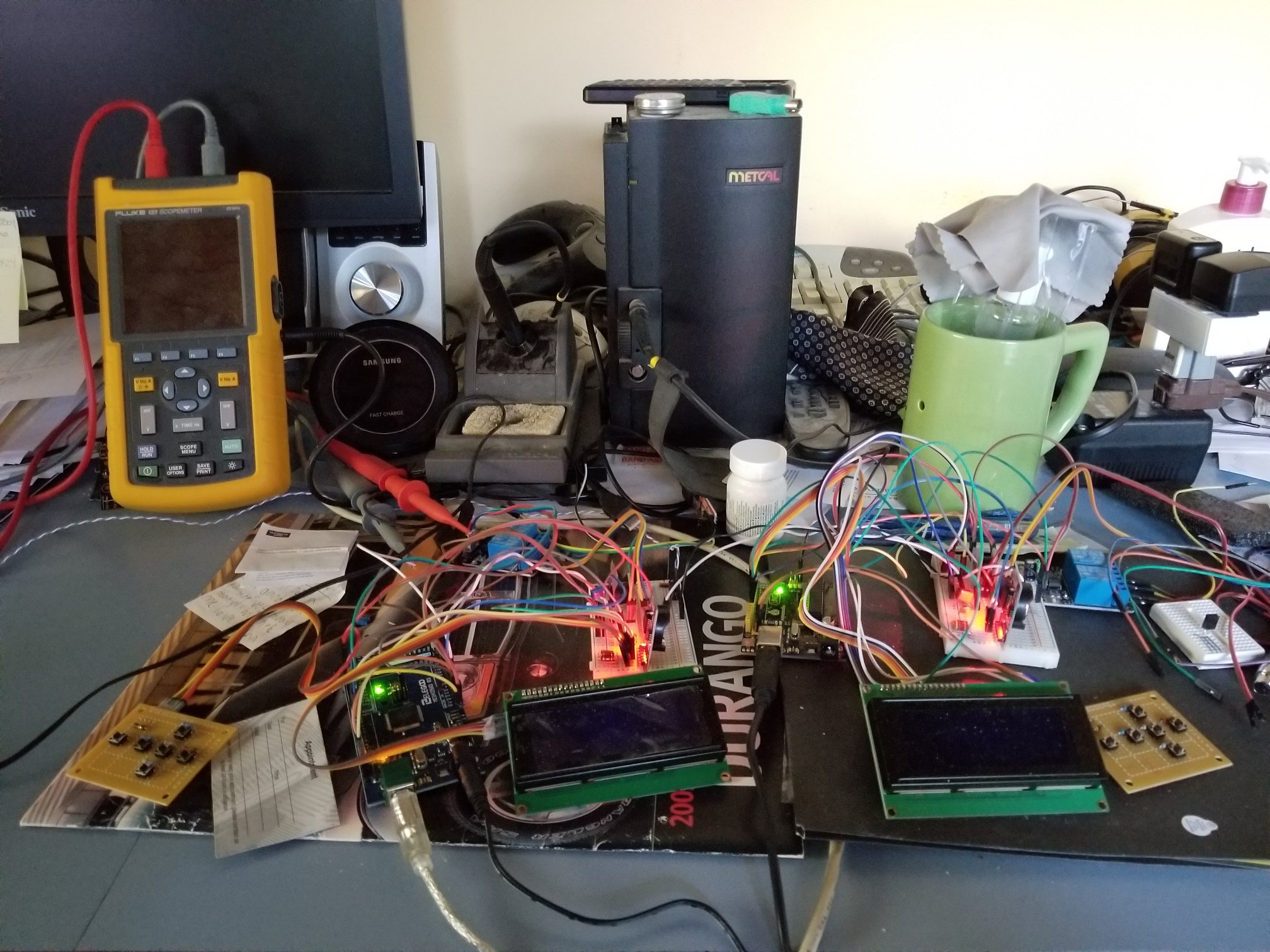
That's mine in the back of the chaos that is my desk...

metcal_station.jpg


Cheers!
 
Yeah, I'm sure it works great for the right task but that desoldering gun is like two orders of magnitude too big to be useful in my world. I'm dealing with 0201 passives and the tiniest actives we can lay hands on because there ain't much room on an M.2 card :)

That's mine in the back of the chaos that is my desk...

View attachment 619874

Cheers!
What are you working on?
 
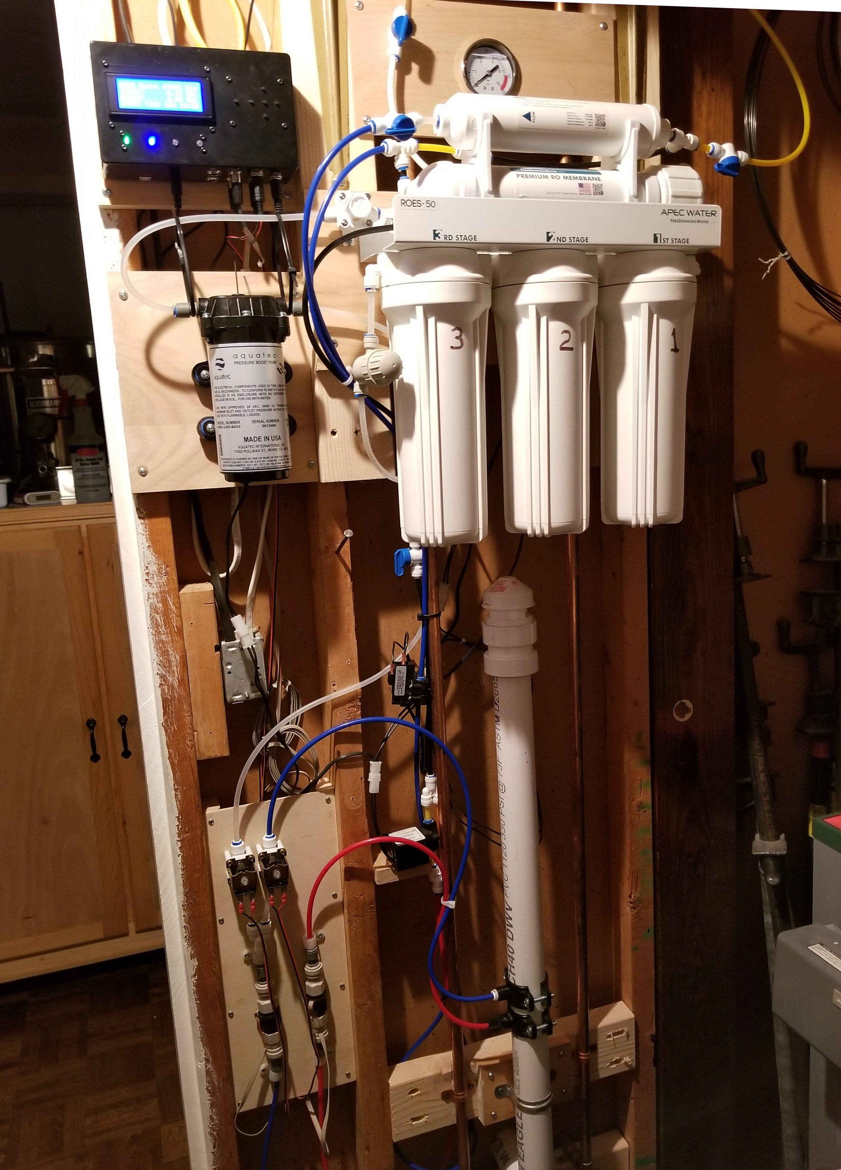
I'm calling it "RO Buddy" for now, and it's for managing my reverse osmosis system. I can program it to fill my brew kettles with the prescribed volume starting whenever I want (within a week), and I can also program it to run the RO system to dump any specific volume (on a 1 to 7 day period) to keep the membrane from fouling from lack of use.

I use an inexpensive ds3231 rtc module to offload time-keeping from the Arduino to preserve tick-count fidelity, and so far it'll still run on an Uno as well as a Mega2560. That pic has one of both, the Mega using an I2C display and the UNO a 4-bit parallel. It has a dual relay module to activate solenoids to either supply brewing liquor or dump RO product (for the membrane maintenance function). It'll sound an obnoxious alarm if water is flowing when it shouldn't or meters aren't spinning when they should, and if either is ignored long enough it'll scram the solenoids and keep making noise.

I'm planning on adding effluent metering so I can calculate efficiency and then adding a ds18b20 on the feed-water side as temperature is important wrt membrane performance. I expect at that point to have run out of ram on the UNO and will truncate further development on that platform, never mind if I follow through on coming up with a TDS function on the in and out water...

build_04_sm.jpg


I've had the proto running for a few weeks and it has found two cool bugs (one was a lulu :eek:) and a couple of meh ones. There's nothing like initiation by fire to bring out unconsidered behavior as well as sloppy coding :D


RO_Buddy_30may2019_sm.jpg


This system currently runs at a reliable 50 gpd but I'll be upgrading to 100 gpd (basically a membrane change, higher capacity pump and higher flow capillary restrictor).

Anyway...this is what happens to a techno-dweeb on the cusp of retirement with lots of toys and spare parts to play with :D

Cheers!
 
Aww, it's all good! :) And may be good for you, too! I have to say this particular effort has actually sharpened my aging brain.

I am not a coder, I'm a hardware guy, have been since '73, and outside of getting through school (reams of dusty decks back then, kiddies) and constructing simulations for work (especially when I was doing asic designs) coding was only done when I couldn't cajole someone else to do it ;)

This is 2600+ lines long and it took a hella lot of Googling to get to where it actually works reliably. I mean, it's not a space shuttle launch, but just getting the RTC and its alarm function fully operational took a couple of weeks because there are a lot of "not quite complete" RTC libraries out there and if you start with the wrong one (or three) it'll/(they'll all) eventually bite you right in the @ss.

Anyway...I'm rambling...Time for another pour :D

Cheers!
 
That reminds me of a funny bug in my own personal logic. :)

When I kept a reef tank I used RO water. I had a timer to remind me to grab the 5 gallon bottle before it over-filled. Well, one day I didn't hear the timer and my wife screamed because I flooded the kitchen floor. After explaining why I didn't hear the timer and how I'd had it all planned out time-wise so that I would know when it was full, she asked me why I didn't just leave the jug in the sink.

:confused:

Sometimes it's tough to see the forest for the trees. :D
 
Bingo. Stupid engineer documentation trick ;)

The grounds versus control signals were swapped at their respective switch inputs. Here's the corrected drawing...

Cheers!

View attachment 258926
hey im on to installing the on/off/auto switch, turns out i only had 5 amp switches so im waiting on 10amp ones. but in the meantime id like to ask. I understand the left side pins of your schematic from years ago. But being im using cadi's shield, are the right side pins still correct? B-NO to the UNO D5/D6 pins through the shield and B-NC to UNO GRD? And im stumped on the B-C pin to the LED pull ups.
ac_power_switching_page_01-jpg.258926


Also is the process to setup the HC-05 the same as the original post? i got this usb dongle i thought i read somewhere on here. https://www.amazon.com/gp/product/B072K3Z3TL/ref=ppx_yo_dt_b_asin_title_o00_s00?ie=UTF8&psc=1


Im going to go back through this whole thread a again to see if i can answer my questions, but any help is much appreciated.
 
I'm calling it "RO Buddy" for now, and it's for managing my reverse osmosis system. I can program it to fill my brew kettles with the prescribed volume starting whenever I want (within a week), and I can also program it to run the RO system to dump any specific volume (on a 1 to 7 day period) to keep the membrane from fouling from lack of use.

I use an inexpensive ds3231 rtc module to offload time-keeping from the Arduino to preserve tick-count fidelity, and so far it'll still run on an Uno as well as a Mega2560. That pic has one of both, the Mega using an I2C display and the UNO a 4-bit parallel. It has a dual relay module to activate solenoids to either supply brewing liquor or dump RO product (for the membrane maintenance function). It'll sound an obnoxious alarm if water is flowing when it shouldn't or meters aren't spinning when they should, and if either is ignored long enough it'll scram the solenoids and keep making noise.

I'm planning on adding effluent metering so I can calculate efficiency and then adding a ds18b20 on the feed-water side as temperature is important wrt membrane performance. I expect at that point to have run out of ram on the UNO and will truncate further development on that platform, never mind if I follow through on coming up with a TDS function on the in and out water...

View attachment 619912

I've had the proto running for a few weeks and it has found two cool bugs (one was a lulu :eek:) and a couple of meh ones. There's nothing like initiation by fire to bring out unconsidered behavior as well as sloppy coding :D


View attachment 619918

This system currently runs at a reliable 50 gpd but I'll be upgrading to 100 gpd (basically a membrane change, higher capacity pump and higher flow capillary restrictor).

Anyway...this is what happens to a techno-dweeb on the cusp of retirement with lots of toys and spare parts to play with :D

Cheers!
and i hate you even more seeing this....thats awesome, i have to physically hook up my ro system to fill my
htl and brew pot a day or 2 before brew day.....im so jealous of all your stuff.
 
Yes, all of the UNO pin labels at the left side are still logically (if not literally) valid. For that matter all of the labels all over the schematic are still logically accurate. The LED pull-ups on the Cadibrewer board connect to the two pin header on that shield and are labeled H and C. They supply the anode current to light up the LEDs either when the controls (UNO D5 & D6) are driven low (and the switch is in the Auto position) - which is the "on" state for the relays - or when a switch is in the On position (which manually grounds the corresponding LED cathode).

I could simplify the drawing and it would likely be more obvious what's going on - I suspect the multiple connections to UNO D5 & D6 is confusing.

As for the HC-05 - there are numerous iterations of HC-05 (and -06) modules available but I can only vouch for the specific model I used in the write up.

And wrt dongles, what you have there looks like an FTDI adapter - ie: USB to serial. Not needed for this project - if you were doing BrewPi over Wifi you'd need that to program the ESP8266 into a bridge. For BrewPi over Bluetooth you just need a USB Bluetooth dongle...

[edit] https://www.homebrewtalk.com/forum/threads/how-to-brewpi-over-bluetooth.508151/

Cheers!
 
Last edited:
hey im on to installing the on/off/auto switch, turns out i only had 5 amp switches so im waiting on 10amp ones. but in the meantime id like to ask. I understand the left side pins of your schematic from years ago. But being im using cadi's shield, are the right side pins still correct? B-NO to the UNO D5/D6 pins through the shield and B-NC to UNO GRD? And im stumped on the B-C pin to the LED pull ups.
ac_power_switching_page_01-jpg.258926


Also is the process to setup the HC-05 the same as the original post? i got this usb dongle i thought i read somewhere on here. https://www.amazon.com/gp/product/B072K3Z3TL/ref=ppx_yo_dt_b_asin_title_o00_s00?ie=UTF8&psc=1


Im going to go back through this whole thread a again to see if i can answer my questions, but any help is much appreciated.

Yep, everything should work the same on the shield as it did on this schematic.

As for the LED's, hook one side up to the B-C post and the other side to the header pin on the LED header on the shield. There is an associated pull up resistor on the shield to complete the schematic. Should work as intended. Let me know if I'm not explaining this well.

As for the HC-05, check out the last few posts in the How To BrewPi over Bluetooth thread. @LBussy posted some instructions that may be helpful to you in getting the bluetooth up and running.
 
and i hate you even more seeing this....thats awesome, i have to physically hook up my ro system to fill my htl and brew pot a day or 2 before brew day.....im so jealous of all your stuff.

lol! Thanks, I tend to find the hard way to do stuff just for the challenge.
I mean, I could just use a float switch, but where's the fun? :D

CHeers!
 
Thank y'all again. I believe I understand. One side of LED to the switch post and the other to the PCB led header.

And sorry I had 2 tabs open and thought this was the Bluetooth thread. Haha.
 
These threads are a little "incestuous" ... the shield supports the BT connection and so on. I think posting in one gets all the same people as the other. I certainly see the same names over and over again.

That dongle makes it easier (IMHO) to get the BT devices set up initially. That's how I wrote my instructions. @day_trippr did the original instructions using voltage dividers which intimidates some folks. I can do it the hard way but reach for that dongle anyway if that tells you anything.
 
A little update, i booted up my box and the relay started clicking on and off only one of the relays (IN1). I thought it was a short so i took everything out and couldnt see anything that would be shorting. So my next thought was it was a bad relay, so i ordered another. But in the mean time i figures i look to see if it was the shield, I had a 2nd board i had built out and swapped it. Well that worked. So i guess i have something shorting on the shield. Im going to have to go throught all the capacitors/resistors that run the IN1 relay and see if there is some solder that shorting or a bad part. ugh. But at least i got my box completely set up minus the bluetooth
 
And now, my red led comes on when it is cooling .....it is wired to the heater switch. So the only thing I can think would cause this would be a shot on the shield on the led posts. Am I correct on this thinking?

The heater manual switch turns the heater and the red led on. And the cool manual switch turns the freezer and the blue led on. So that wireing is good.
 
Power comes from the LED pin to be grounded through pin 5 or 6. You have a short, but I don’t think it’s the LED pin. It could be at the relay pins.
 
Power comes from the LED pin to be grounded through pin 5 or 6. You have a short, but I don’t think it’s the LED pin. It could be at the relay pins.
Are you sure? i have it wired via this diagram. I thought is was the LED pin because when cool is on the red light lights up not the blue and they are plugged into the correct pins. im gonna take it apart this evening and troubleshoot.

ac_power_switching_page_01-jpg.258926
 
Are you sure? i have it wired via this diagram. I thought is was the LED pin because when cool is on the red light lights up not the blue and they are plugged into the correct pins. im gonna take it apart this evening and troubleshoot.
I'm never sure what people wire together. :) I am however sure that the v1.2 of the shield has a pull up wired to VCC to power the LEDs. The only thing that's going to cause them to light up is a shunt to ground. That's either through the relay to pin 5 or 6, or you have the switches wired incorrectly.
 
HA. well Im kinda sure it is wired correctly via that diagram. I was just under the impression the B-C terminal was hot and not ground. So assuming i am wired correctly, im trying to figure out how the Heat LED is getting power when it is in cool mode.
 
Pins 5 and 6, when used with relays, are "inverted" and therefore sinks. If you have them as non-inverted then they are a source of power and the LEDs must be grounded elsewhere. Either way, it's not a short at those LED pins.
 
Last edited:
Ok I got it all figured out. Turned out I had my heating and cooling hot wires on the wrong relays which triggered the opposite led to turn on. (Heat/pin5 and cool/pin6). I had the setting to match those pins that correctly which turned on heating and cooling but it would turn on the other LED. So I changed the pin settings in fermentrack and swapped to hot wires on the relays(heat/pin6 cool/pin5) And now it all works.

This might be for another thread but I did notice I had some screen scrabbling when I was packing the box back up. So I turned it off then back on. This made the controller lose all the assigned devices. I do not believe that should happen, as if a power failure should occur I shouldn't have to reassign the relays and probes, should I?
 
Screen scrambling is common with the shift register/parallel LCDs although some folks (me) don’t get it so it’s hard to troubleshoot. The screen in the original code never fully refreshes, so any weirdness persists. I put in a screen reset on a timer to clear it (thank you Thorrak). I need to see what version it is but I thought it was in 0.2.11. What firmware version are you running?

No, the devices should not have gone away. As a matter of fact you should have to make a very concerted effort to clear them. That’s one of the benefits of a controller vs a computer running a program. When you say you turned it off and back on, how did you do this exactly?
 
Lee, as you've been playing with the AVR code lately, have you noticed if the command suite includes a "wipe out the configured device list" function?

When I was first getting BrewPi over wifi working there were numerous instances of the device list being cleaned out when the comms were flakey. At the time (years ago now) it sure looked like the BrewPi host was essentially disabling the AVR and forcing it to be configured again...

Cheers!
 
Well i just remoted in and i see the screen has no probes, and is in Celsius. So yes, It is cleaning out my devices.

The firmware i flashed wasnt the one that you are maintaining. IT was the one that said "compatible with cadibrewer's shield" Should i reflash with your firmware? Is it compatible with shield's? Do i need to wipe the Uno first?
 
Afaik all versions of the AVR code are compatible with the shield. That includes 0.2.4 and 0.2.10 for sure (I've used both) and Lee's 0.2.11 mod...

Cheers!
 
There is a "lose your mind" function, yes. Basically you echo "E" to the port if I'm remembering right. There's also a button in the control panel. Given the electrical issues @Car Ramrod is having, I'd be hesitant to declare it an application issue. Always willing to explore possibilities though. I'd still like to know what "turned it off then back on" means specifically.

I'd recommend using the latest release version 0.2.11 of the firmware. It has the reset timer to get rid of scrambling if/when it occurs.
 
Will do i will reflash tonight. I believe i will have to hard wire it to re flash correct? Do i need to completely wipe the UNO or is reflashing all that is needed?

Turned it off and back on was i have a power switch on the control box. So i cut all power to the box, then turned it back on. FYI i did it again later last night and it didnt lose the devices.
 
I'm running 0.2.10 across the fleet, fwiw.

Does the 0.2.11 firmware support erasing the eeprom? Because now that I think of it I'm vaguely remembering folks that had the symptom of losing device assignments on a power-cycle that was "cured" by manually wiping the eeprom then configuring the devices again...

Cheers!
 
I'm running 0.2.10 across the fleet, fwiw.
The significant differences between 0.2.10 and 0.2.11 was moving to PlatformIO (which compiles with updated libraries so who knows what changed - hopefully all good changes) and adding the reset LCD on timer function (a few other small things.)

Does the 0.2.11 firmware support erasing the eeprom? Because now that I think of it I'm vaguely remembering folks that had the symptom of losing device assignments on a power-cycle that was "cured" by manually wiping the eeprom then configuring the devices again...
It does:
Code:
elif messageType == "resetController":
     logMessage("Resetting controller to factory defaults.")
     bg_ser.write("E")
That's the part that does it in brewpi.py. One can either use the (extremely scary) sockettest.php page and send a blank message of type "resetController" to execute that, or use Maintenance Panel -> Advanced Settings -> Reset Arduino to factory defaults (all the way at the bottom.)
 
Well I reflashed both controllers with 0.2.11. i had some organization to do in my keezers so moved my completed controller to the other freezer. Everything was going well. Then i used the rotary encoder to set fridge constant and a temp, clicked ok, and it switched to waiting to cool. Then boom, screen went blank for a half second, then cam back on with no probes and in Celsius. Wouold this have anything to do with physically moving the device while on?

Started to kinda make me mad as i have set these things up multiple times last night, but i got pretty fast at it as i memorized all the probe numbers and such, lol. So i shut it down and turned it back on and it cam back to Fahrenheit but no probes. Re set the probes and been running all night. So idk how to recreate this wiping of the devices.
It's certainly not supposed to happen like that. But, you've recreated the issue with two versions of the firmware - one very well matured and one compiled with a different set of libraries and minor changes. I'd be leaning towards a hardware/environmental issue of some sort. "Just moving" and having the screen blank like that sounds a lot like the Arduino lost power, so there's a loose connection somewhere I'm guessing. When the serial port is re-opened (like if the dongle resets) the Arduino will reset as well so the connection could just be that power supply.

Back to what @day_tripper was saying/remembering, I'd try first to reset the eeprom. Use the Maintenance Panel, Advanced Settings, "Reset Arduino to factory default" all the way at the bottom. Then set up your devices, then see if that helps. If you are still having issues, try without the bluetooth or wireless cards and see if that causes it to stop. Those should be simple serial connections, but it's incredibly simple to reset the eeprom (all it has to receive is an "E") so any weirdness when the other card starts up could potentially cause the Arduino to lose it's mind.

Remind me, are you using BT or the ESP8266? If the latter, what serial bridge are you using?
 
Ok. I have reset eeprom a few times but never a full reset of the Arduino. I'll try that. I am using the hc 05 Bluetooth.
 
Back
Top