How To: BrewPi LCD Add-On

Homebrew Talk - Beer, Wine, Mead, & Cider Brewing Discussion Forum

Help Support Homebrew Talk - Beer, Wine, Mead, & Cider Brewing Discussion Forum:

This site may earn a commission from merchant affiliate links, including eBay, Amazon, and others.
What we know:

- UNO green LED on: power good
- UNO amber LED on: script ran far enough to turn on IO13 (to the "blink" LED).
- BrewPi host can't talk to the Uno suggests the comm lines aren't working.

So, unsolder the wire from IO1, make sure the IO 0 and IO 1 pins aren't shorted to any neighbors, then see what happens....

Cheers!
 
Thanks for all your help with this by the way.

My pleasure. :mug:

They were both lighting up on the uno as far as I could tell but the LEDs on the shield were doing nothing (I've not done your tweak to the board LEDs for heating and cooling)

That's fine, the key is those LEDs are telling you you didn't break the Uno.

In terms of soldering and trying to make it easier for me, would you recommend leaving the component tailings on, before attaching the wires? the reason i ask is that i tidied up the component tails as i went along and in hindsight for my shake hands i think it would have been much easier to get everything soldered up and then do the tidying right at the very end.

I typically insert everything with full-length leads, bend both leads on 2 pin parts just enough to keep them in place, then do the same with a pair of corner pins on multi-pin parts. Then I'll solder everything, then go back and clip leads so they are just proud of the surface.

I probably should have suggested using 24 or 26 gauge solid insulated wire in my instructions (I'm going to edit that in right now). It's a hella lot easier to work with than stranded, and there's no reason to go much heavier.

I'm hoping to make the changes today, but i have to take a shed load of milk bottles and turn them into a throne for an ice princess this evening... joys of fatherhood!!!

LOL! Good Daddy! You have your priorities right :D

Cheers!
 
So I have a shield wired up now and it all seems to be going well in temp probes work as does the heater and chiller, but I need to get a beer on for the end of the month and couldn't get the LCD to register, but I think that's just because I've not got the wires to the right pins going to get some female to female jumpers and get it working when they arrive
 
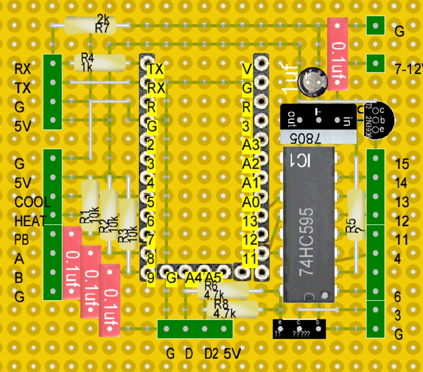
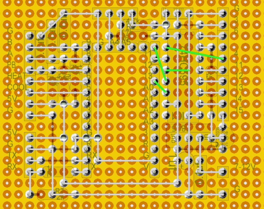
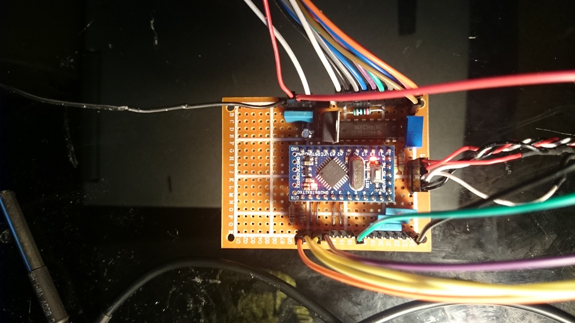
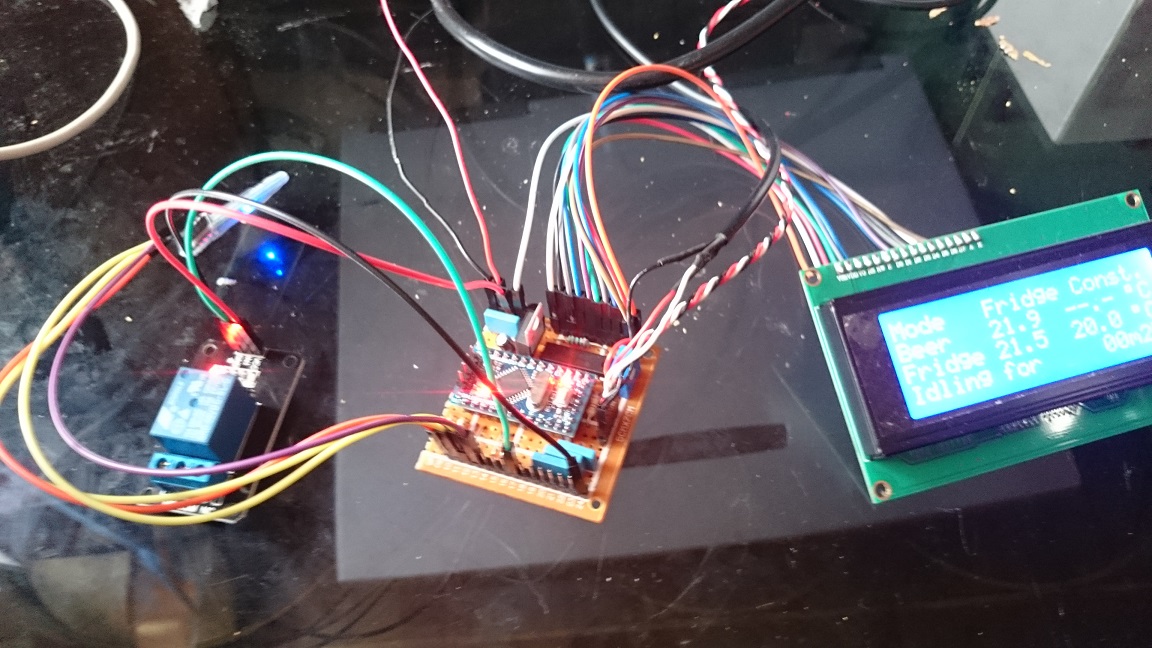
I made a PCB version for the arduino mini.

To control the backlight i used a 2N3906 PNP transistor, not sure if a 220 ohm resistor at the base is well suited.

Feel free to copy the design and comment your remarks.

Front.jpg


Back.jpg
 
Yellow is definitely not my friend ;)

- do you have a matching schematic?
- what is T1 doing?
- what is the "7805"? Is that a pot or a voltage regulator?

Cheers!
 
Its mostly based on your lastest schema from page 2 of this thread.

Yes, this is a 5V voltage regulator, i thought the Arduino mini regulator is not able to produce enough power on its own for Bluetooth and Display.

The backlight controller is just pin 2 from the shift register trough a 220 resistor on the gate, 5v on the collector and the emitter straight to pin 15 of the LCD.

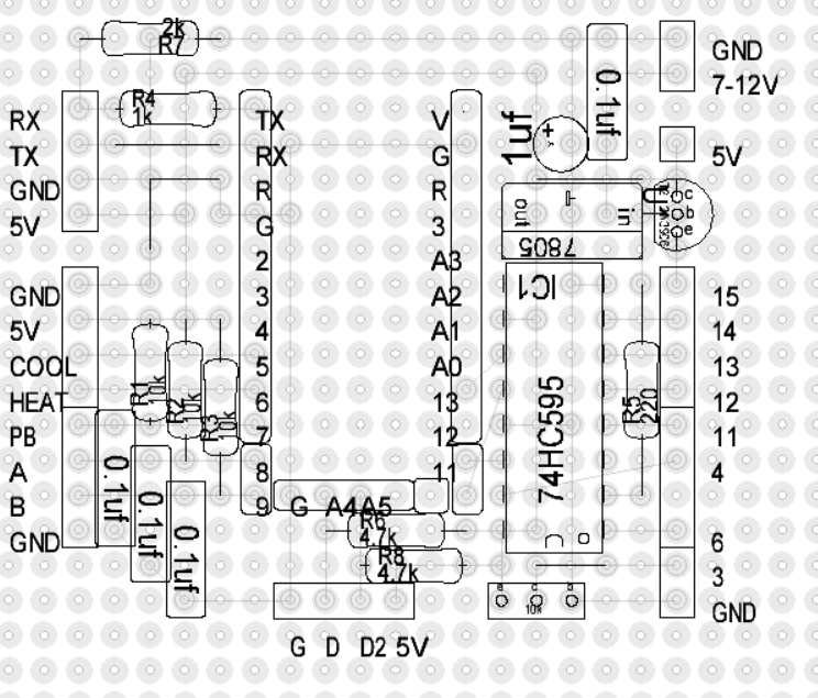
Front.jpg


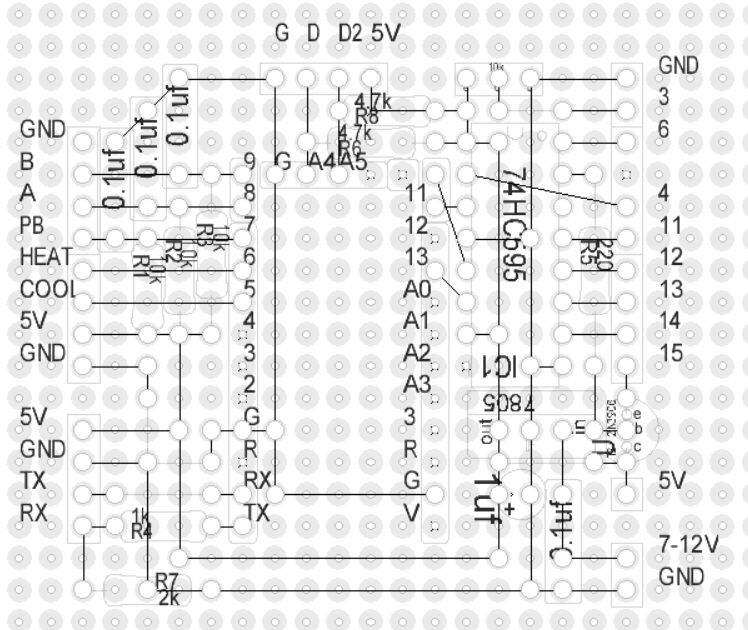
back.jpg
 
It is done, display backlight turns itself off after 10 minutes.

Made some small changes to the layout, there are all outputs on the board now, just the door switch is missing.

front_new.jpg


back_new.jpg


DSC_0412.jpg


DSC_0414.jpg
 
The backlight controller is just pin 2 from the shift register trough a 220 resistor on the gate, 5v on the collector and the emitter straight to pin 15 of the LCD.


Ah this! Didn't look so well, sorry about that.

Ok so as I said before I'm an electronics beginner and I don't know what this means by the 'gate' and I assume the 'emitter' and 'collector' are terminals on the rotary?

If you could be so kind as to add that to the latest schematic, that would be awesome.

Great thread man thanks for doing all you have done here! This project has taught me a bit about electronics and raised some interest for sure.
 
Here's an updated schematic for my BrewPi shield design including both the original BSS84 P-channel FET for the LCD backlight dimmer feature, along with what I gather doomy86 did using a PNP transistor and 200 ohm resistor to implement a backlight dimmer.

As noted, with either backlight dimmer option present, the LCD will wake up if Uno pin D7 is grounded (usually by the pushbutton on the rotary encoder switch)...

Cheers!

[edit 02/05/2015: corrected P-FET G/S pin swap]

BrewPi_LCD.jpg
 
Awesome!!

That's great news. So stoked on this, thanks for the update!
 
Day_trippr, maybe I missed it somewhere but what is 'SI option' ?

Oh - LOL - I had been leaving that out of the posted schematics but this time forgot to remove it.

Back at the beginning when I threw all the parts on a bread board I poked around with a 'scope looking for signal integrity issues that might explain why some folks were seeing character errors on their LCDs.

The HC series dates back to the 80s and was one of the early high performance mixed technology families. To get there they took pretty much all of the damping out of the front end and shifted thresholds lower. The result is the parts definitely do not like negative overshoot on clock signals, as the positive recovery can cause false triggering - while still being well below the minimum specified switching threshold.

And I was seeing a solid 1.2 volt overshoot on the signals from the UNO to the shift register, and a pretty hefty bounce back. While I wasn't seeing character errors on the LCD it looked like that was just a matter of time. By inserting 33 ohm series resistors in those three signals, their edge rates are slowed enough that the overshoot is almost totally removed.

This overshoot isn't present on my shield boards, likely due to the very short wires (in the inch range, vs the 8 inches for the Dupont jumper wires), so I've been leaving those resistors off the boards and the drawing....

Cheers!
 
Thanks for the answer. Looks like the BSS84 pfet only comes in a SOT23 package. At least thats all i'm finding. Now to figure out how the hell I'm going to use that.... :)
 
LOL! Yes, they are tiny little effers. I have to put on my magnifier headset to have a prayer of even finding them.

You could follow doomy86's lead and use a 2n2906. Those can be had in all kinds of through-hole packages...

Cheers!
 
day_trippr I was looking at your latest schematic and trying to wrap my head around how this works with the PFET in there and I have a question. Since this is a PFET don't we supply V+ to the source and control it from the gate? You have 5v at the gate and pin 2 of the shift register going to the source pin. Is that right or am i thinking about this the wrong way? I'm just trying to understand how this works. Thanks for putting up with me. :)
 
So my rotary encoders finally arrived from China having taken four weeks to float here. Ironically there is now a competitive supplier on Amazon Prime - two day delivery. <sigh>

Anyway, wired one of the switches to my debug BrewPi minion in no time and it worked perfectly. Press the button and you can walk through the settings and change them if desired. Could be handy when I'm down in the brewery and want to change something without running back up to my office or using the keezer RPi monitor.

Then it was time to solder in the BSS84. Though the SSD designs I create actually have hundreds of parts that make a BSS84 look huge, it's still hella small when your eyes are 60+ years old ;)

But I got it installed cleanly and now everything works as expected. The LCD backlight shuts off in 10 minutes and will light up when the rotary pushbutton is clicked. Very cool feature that should extend the LCD display lifespan.

When I get a chance I'll see if I can take a macro shot of the BSS84 soldered to the back side of the protoshield. Hopefully it'll be more than just a black speck. I need to buy one of those USB microscopes, I think...

Cheers! :mug:
 
Hopefully my encoders are on the same boat yours were :) Should get my BSS84 pfets tomorrow. I would be interested in where you soldered yours if you do have a chance to get a pic. Thanks again Day_trippr!
 
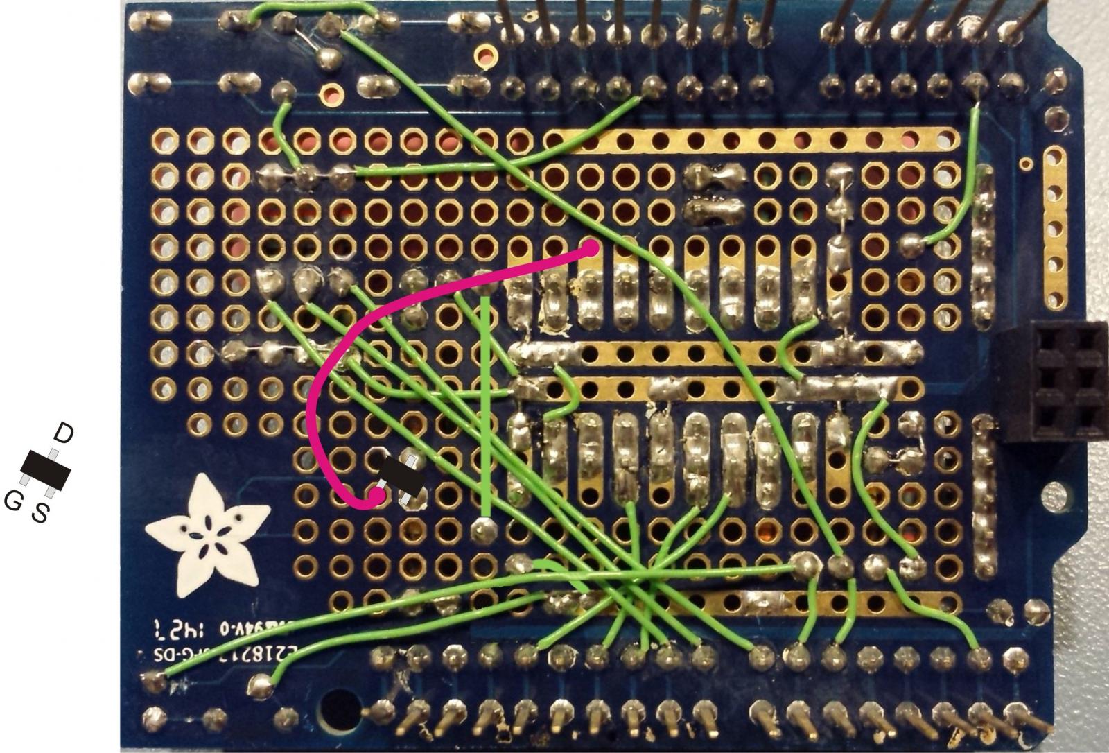
In case I don't get to it quickly (or if the pic turns out crappy), here's what I did:

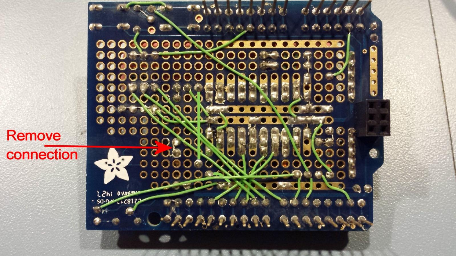
While my schematic shows the p-fet between the shift register pin 2 and the first diode, it can go anywhere in the series connection from SR to LCD. And the easiest place to stick it was between the diode and resistor as that had a short (.1") wired connection.

So I removed that short wire connection on the back of the protoshield and soldered the p-fet in its place, rotating it around 30° or so to line up the pins. That put the gate pin over its own via which made wiring to the shift register output easier than soldering straight to the tiny p-fet pin.

Piece o' cake :D

Cheers!

build_07.jpg


pfet_install.jpg
 
Ok that was a PITA. My close vision is not what it used to be. My soldering Isn't what it used to be either heh. Some sorta big blobs but hey it works. Took your placement advice Day_trippr. Here is a crappy phone pic.

pfet-64937.jpg
 
Perfect - exactly how how I did it, just slightly smaller blobs ;)

Well done! :mug:

Awesome stuff. I've been using a simple temp control circuit with the ethernet shield for a while now and logging to Xively. But I'm moving over to brewpi because I have all the stuff sitting around, great post!!

Day_trippr....
Is this the encoder youre using? http://www.amazon.com/dp/B00KHTLWU6/?tag=skimlinks_replacement-20

Have you done much design of PCBs? I'm thinking this would be a pretty simple PCB design since Elco stopped the production. The project could be uploaded to OSHPark and had for about $10/board. I may work up a design if I find some free time.

For the folks that are having a hard time with soldering...
If you are using a radio shack pencil, I HIGHLY suggest you get a soldering station. Places like circuit specialists have analog or digital adjustable stations for $30-50 usually. I cannot stress enough how much this changed my interest in electronics. I was so frustrated before with the radio shack pencils. I went through like 4 of them, a total waste of money. Now, with the station, its a 1 second hold and then apply solder. Beautiful joints, every time.

I also use a hakko brass ball tip cleaner, this is about 100x better than a wet sponge as it does not reduce the temperature of the tip.

I realize I'm telling everyone to spend more money than they probably want to, but if it seems like something you'll stick with, you definitely want to make these changes.
 
Last edited by a moderator:
And as a clarification, there is really no point in the pfet if using the rotary encoder right?


Depends... With the pfet in place, the brewpi will turn off the display after 10 minutes. Tapping the encoder will wake it back up. Without the pfet the display will be always on. It's up to you if that matters.

I h ave a weller soldering station and iit works great. Most of the time I have no issues with soldering. The only issues I've had on this project are the places I have had to try to solder the pfet or wire to existing solder points. Sometimes i end up with too much solder. Really I'm just out of practice.

But the screen can be turned off manually with the rotary encoder right?
 
[...]Day_trippr....
Is this the encoder youre using? http://www.amazon.com/dp/B00KHTLWU6/?tag=skimlinks_replacement-20

Yes, I have one of those encoders, as well as a pair of same-but-different-manufacturer switches, running on various minions.
They both work well and have similar tactile characteristics.

Have you done much design of PCBs?

Aside from stints doing chip design and platform architecture, board design has pretty much dominated my 41+ year career.
So, yes, a bit ;)

I'm thinking this would be a pretty simple PCB design since Elco stopped the production. The project could be uploaded to OSHPark and had for about $10/board. I may work up a design if I find some free time.

Please feel free to use anything I've posted on any of the HBT forums, you're more than welcome.
A fully-loaded double-sided Uno R3 shield solution should be a piece of cake.

But if you pay $10 a circuit, make sure you get kissed first ;)
If you get to where you're actually looking for a volume fab shop let me know.
The ~ 1" x 3.5" pcb below is for a 2TB SSD I designed for the current MacBook Pro and is 10 layers, scary tight geometries, controlled impedance, and costs about a buck and a half...

Cheers!

caldwell.jpg
 
Last edited by a moderator:
No, that's a function of a 10 minute timer in the Arduino.

So I would say there's no point in installing the backlight control circuit without at least a push-button switch...

Cheers!

So arduino code shuts down the screen after 10 minutes? And you need the rotary or a switch of sorts to turn the screen back on...

So what is the pfet or the tranny doing in the other design exactly?
 
Yes, I have one of those encoders, as well as a pair of same-but-different-manufacturer switches, running on various minions.
They both work well and have similar tactile characteristics.


Aside from stints doing chip design and platform architecture, board design has pretty much dominated my 41+ year career.
So, yes, a bit ;)


Please feel free to use anything I've posted on any of the HBT forums, you're more than welcome.
A fully-loaded double-sided Uno R3 shield solution should be a piece of cake.

But if you pay $10 a circuit, make sure you get kissed first ;)
If you get to where you're actually looking for a volume fab shop let me know.
The ~ 1" x 3.5" pcb below is for a 2TB SSD I designed for the current MacBook Pro and is 10 layers, scary tight geometries, and costs about a buck and a half...

Cheers!

ummm yeah no thanks! I'm a civil engineer with an interest in electronics and all things fun! haha. That does not look fun. I have a hard enough laying out simple tone circuits for guitar effects I play with. I've mostly resorted to just populating easily purchased fabled PCBs.
 
So arduino code shuts down the screen after 10 minutes? And you need the rotary or a switch of sorts to turn the screen back on...

So what is the pfet or the tranny doing in the other design exactly?

The BrewPi AVR code sets the state of shift register output bit 2 to a "1" after 10 minutes from start up. If you then short UNO digital IO pin D7 to ground, that tells the AVR code to set S/R bit 2 to a "0", which enables the p-fet or the PNP transistor to conduct power through to the LCD back light LEDs, and also restarts the 10 minute timer.

The recommended rotary encoder includes a push button function, but you could substitute a simple push button switch do that much. You'd lose the ability to actually change BrewPi settings without the rotary encoder part, but you'd gain the dimming function...

Cheers!
Hmmm... OK. Maybe I'll add one.

Any suitable tranny subs? I dont have any pfets so far as I know in my arsenal. Most of the trannies i have are npn, plus some irf510 and j201s. I think the only PNP i have are 2n39xx? I dont think i have any 2n7002.

also, is there anything that is worth setting via rotary over web interface? I already have the pi up and running, about to jump out and solder the ic socket for the shift register and some of the wiring
 
@andrewmalizia
Just use a 2n3906 like in daytrippers schematic.


I have some problems with both of my brewpi builds, they work ok standalone but with a load connected (aquarium heater) the display gets scrambled after some time (5-10 heating phases).

I suspect there is feedback noise from relay switching, dont have an oscilloscope so i cannot be sure. I have already installed a decoupling capacitor right at the VCC input of the shift register. No change.

My relays have optocouplers, but i dont like the idea of installing a second power source, so i tried feeding the relay directly from the wall wart. No change.

The leads from the arduino to the shift register are already very short ~1cm, from the display to the shift register they are somewhat longer ~15cm.

You can find details of my build here:

https://doomlab.wordpress.com/2015/02/18/brewpi-build/

Any help would be really appreciated.
 
I'm all about change. PKU. ;)

Actually, what happens is the forum won't let me go back and edit posts after some number of days/weeks/I'm not sure what, so I have to keep adding revisions - especially if a chunk of the design hasn't been verified because the parts are on the slowest boat from China ever...

Cheers!
 
I have some problems with both of my brewpi builds, they work ok standalone but with a load connected (aquarium heater) the display gets scrambled after some time (5-10 heating phases).

I suspect there is feedback noise from relay switching, dont have an oscilloscope so i cannot be sure. I have already installed a decoupling capacitor right at the VCC input of the shift register. No change.

My relays have optocouplers, but i dont like the idea of installing a second power source, so i tried feeding the relay directly from the wall wart. No change.

The leads from the arduino to the shift register are already very short ~1cm, from the display to the shift register they are somewhat longer ~15cm.
[...]

If you disconnect the AC loads on the relays do you still get display errors?
Do you know if your relay modules have snubber diodes across the coils?
Also, what is the actual 5VDC level at the LCD?

btw, at least one other person has gone through this and I believe eventually solved it.
Hopefully he'll chime in...or you could start digging back through the thread...

Cheers!
 
Back
Top