• Please visit and share your knowledge at our sister communities:
  • If you have not, please join our official Homebrewing Facebook Group!

    Homebrewing Facebook Group

Finally...beginning my electric brewery

Homebrew Talk

Help Support Homebrew Talk:

This site may earn a commission from merchant affiliate links, including eBay, Amazon, and others.

nspaldi0

Well-Known Member
Joined
Mar 15, 2010
Messages
218
Reaction score
1
Location
Lexington, KY
Finally beginning the initial stages of the brewery. It will be based on a similar cart style 2-vessel system like board member Resslerk has posted. I'll be using 240, so I've started with the spa panel. I'm not electrically minded, but I have studied enough here and figured I could get more than enough good help from this great forum to build this simple electric brewery.

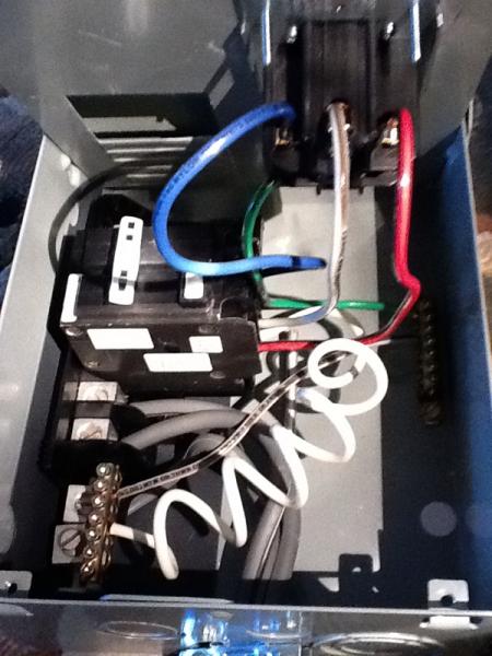
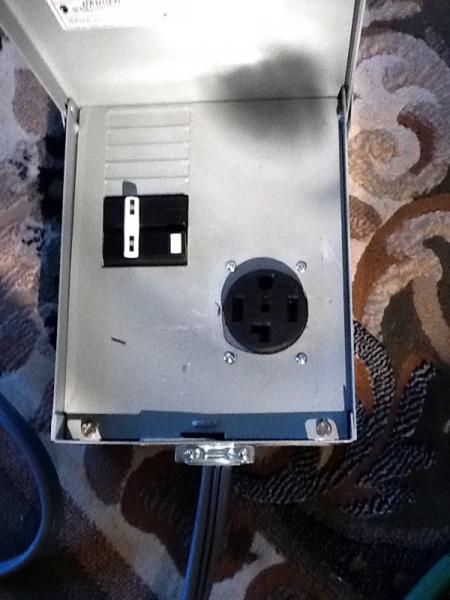
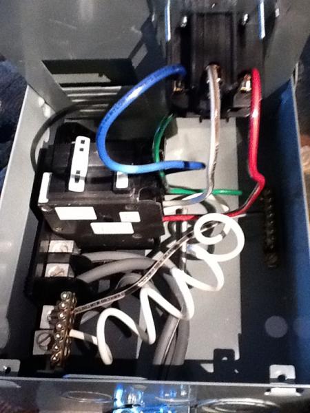
To start, I'm using a 3 prong dryer outlet that is fed from a 30 amp breaker in the main panel. I purchased the 50 amp spa panel and will use a dryer cord to wire into the spa panel. I'll then mount a four wire plug in the spa panel enclosure like others have done.

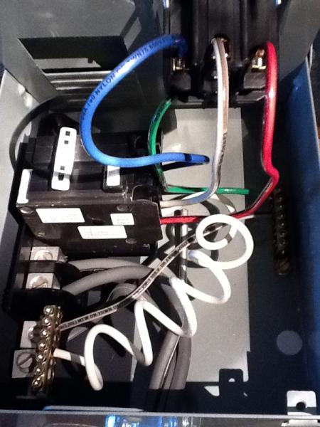
Here's my first of many questions.1) I wired the incoming dryer cord (10/3 cord, 120/250v) according to PJ's spa diagram as shown in the picture below. Should I have taken the ring terminals off and just used bare wire or will it be fine to leave the ring terminals on? 2) Can I use 10/3 wire to wire the 4 prong outlet that will supply the control panel?

Thanks for the help! I've been trying to start this since last November but life got in the way. Feels good to be building another brewery.
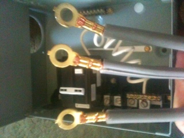
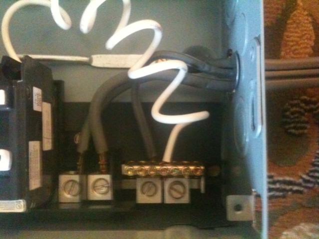
image-3182018605.jpg


image-2428171638.jpg
 
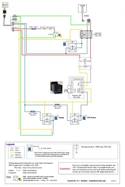
I reread my first post and on my second question, I meant can I use 10 gauge wire to wire the 4 prong outlet into the spa panel? Also, I'll be using this diagram below for the control pane. Thanks To PJ!

image-3885699929.jpg
 
I would use 10 gauge wire, I'm sure your system will be under 30 amps. How did you hook up the wires with the eyelets on? I would have cut them off and stripped the wires but I would have to see how you did it.
 
Thanks. The 5500 watt element, pump and pid will all be running during mash recirculation, so I think I should be ok with 10 gauge correct?

I'll go ahead and cut the ring terminals off and strip the wires.
 
Yes, I would think no problem. Besides, I doubt your wire coming in is going to be bigger than 10 gauge so a bigger wire after it gets there provides no benefit I can think of.
 
Well I wired up the spa panel. How does it look? If it looks ok, I'll plug it in and test it. As you can see, my hole saw wandered quite a bit. I think I'll be investing in a drill press. Anyone recommend a particular brand? I saw one atHome Depot, a Ryobi for $119.

image-4073073031.jpg


image-817837182.jpg


image-3909518708.jpg
 
Just an FYI you don't want to have your neutral and ground bonded in that box that is something that is only done at your main service. Will cause unwanted currents on your ground.
 
Thanks Soultrain. I do believe though that it has been discussed that this is ok when wiring the Spa Panel. I will link to a thread with the discussion if I can find it. PJ has discussed it I believe.
 
PJ or anyone else care to comment on my wiring of the spa panel? Thanks again for all the inspiration to go electric!
 
I am also looking to set a e-brew system.

I have a questions.

What are the benefits of using 2 tanks one for HLT and one for a BK? Why not just use one?
 
I am thinking a Herms system with a cooler MLT for now just to get started. I love the setup at http://theelectricbrewery.com/ but have to start small and lower cost, plus I am only doing 5 gal batches now.

I am going to run a 220 line into my garage where I plan on brewing now. I am thinking just one would be fine because only one of the heating elements would be on at a time. Is that correct? I already have a 110 outlet there so I will have that one also.

Also do you need a PID on all of the pots or would putting temp on MLT and BK with a potentiometer? It's might be about the same price so I guess why not just go with the PID.
 
I tested my spa panel this morning. Test button worked as it should and tripped.

I also started work on the kettles. I've soldered the bottom drain for the MT and punched holes in the HLT/BK. I'll post some photos soon.

Next is to purchase an enclosure and order my parts from auberins. Anyone have any suggestions on size of enclosure for the wiring diagram I posted?
 
I know it's pricey but I have a 16x14x9" Stainless Enclosure NEMA4x waterproof no holes never been used I'm selling for $150. It was too small for my components but should be fine for a smaller system.
 
Hey nspaldi0, I'm along for the ride. As you said in my thread we seem to have similar rigs in mind, and I think we can learn alot from each other's progress/issues.

I have been thinking about a drill press as well, especially after trying to cut the outlet hole through the SPA cover with a dull holesaw and cordless drill (wow was that a pain!) I would say that if you aren’t planning on using the drill press that much than don’t spend big bucks on it. I’ve actually been eying the Harbor Freight model, I think you can get it for under $80 when it is on sale and you use a coupon.
 
Kpr,

Thanks for joining the thread. I know what you mean about the hole for the spa panel. Did you notice mine? The bit was all over the place!

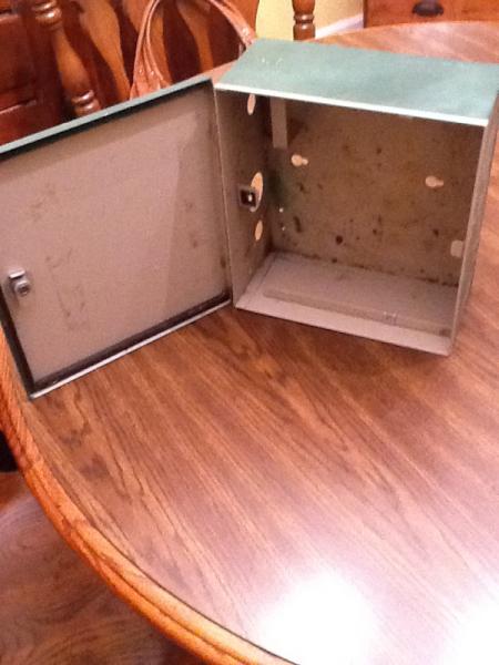
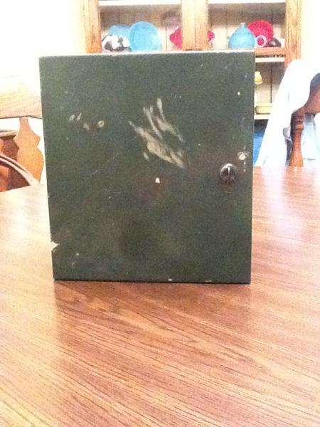
I scored this enclosure for free. It's 11 x 11 x 4.25. Anyone with experience Think it will fit 1 PID, 1 estop and three push buttons? Mine only concern is if I ever decide to upgrade from the two vessel system then I would need to change enclosures. Here's some photos of the enclosure. It has three holes on one side but I'm sure I could reuse them. It's dirty, haven't cleaned it up yet.

image-3996465638.jpg


image-210505638.jpg
 
I ordered all my parts from Auberins tonight! Excited to get them in a few days!! I'm thinking about adding this temperature display that uses an rtd just to display the herms output. http://www.ebay.com/itm/250560351944

Could anyone help me integrate this into this diagram by PJ? PJ, if you see this would you mind helping me add this to the diagram? Thanks for any help!

image-2572583826.jpg
 
nspaldi0 said:
I ordered all my parts from Auberins tonight! Excited to get them in a few days!! I'm thinking about adding this temperature display that uses an rtd just to display the herms output. http://www.ebay.com/itm/250560351944
!

I just ordered that same display. I saw a thread discussing it and looked like a nice alternative to ordering a 3rd pid for just temp display. Most of the people that have it said it was working for their needs.
 
PJ, does the 4th picture over on the eBay ad help with the wiring? Thanks for joining in on the thread. All you're help on the forum is why I'm attempting this build!
 
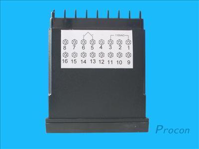
I'll take a stab. Looks like Pins 1 and 3 and used for 120VAC and 5 and 6 are for the RTD. If you wanted it switched the same way as your PID is switched you could just tap it off like the picture I attached. If you don't want it switched you should get your hot line from before the switch.

T800temp.jpg


T800wire.jpg
 
PJ, does the 4th picture over on the eBay ad help with the wiring? Thanks for joining in on the thread. All you're help on the forum is why I'm attempting this build!
Thank you.

The image is way to small for this old man to ever see the details of it.

So sorry.
 
Thanks I3asturd! No worries PJ, I didn't see it until looking at the page three times. One question I have is if I want to add this with it's own push button switch, would I need to add an ssr for this?
 
No the SSR is only for controlling something. That T800 doesn't control anything, it just shows you the temperature. If you added it's own switch would it just be to turn it on and off. There's really no reason for it to have it's own switch. It really doesn't even need to be switched since it doesn't control anything. But, like I said, if you want it switched, just hook it up on the same switch as your PID like I show in the picture I attached above. I you really want it to have its own power switch let me know and I'll redraw it.
 
You're absolutely right. After all, it's just monitoring the herms temp output, so I won't really need it except for during the mash. Plus I'll be able to see what my cooling water temp is at during cooling! I am correct in assuming I can just use pid to monitor my wort temp in the HLT/BK while chilling with the herms coil right? With this wiring diagram, the pid won't run the element unless the element switch is on?
 
Do you have the original image, instead of attaching it, try hosting it on photobucket.com or something and then post the
 
Back
Top