• Please visit and share your knowledge at our sister communities:
  • If you have not, please join our official Homebrewing Facebook Group!

    Homebrewing Facebook Group

Electric System Problems

Homebrew Talk

Help Support Homebrew Talk:

This site may earn a commission from merchant affiliate links, including eBay, Amazon, and others.
This sounds like you are saying that at constant voltage, if the resistance increases, then the current will also increase. This is wrong. Ohm's Law is: V = I * R, where V is voltage, I is current, and R is the resistance thru which the current flows. Ohm's Law can be rearranged as: I = V / R, which clearly shows that at constant voltage, if the resistance increases, the current decreases.

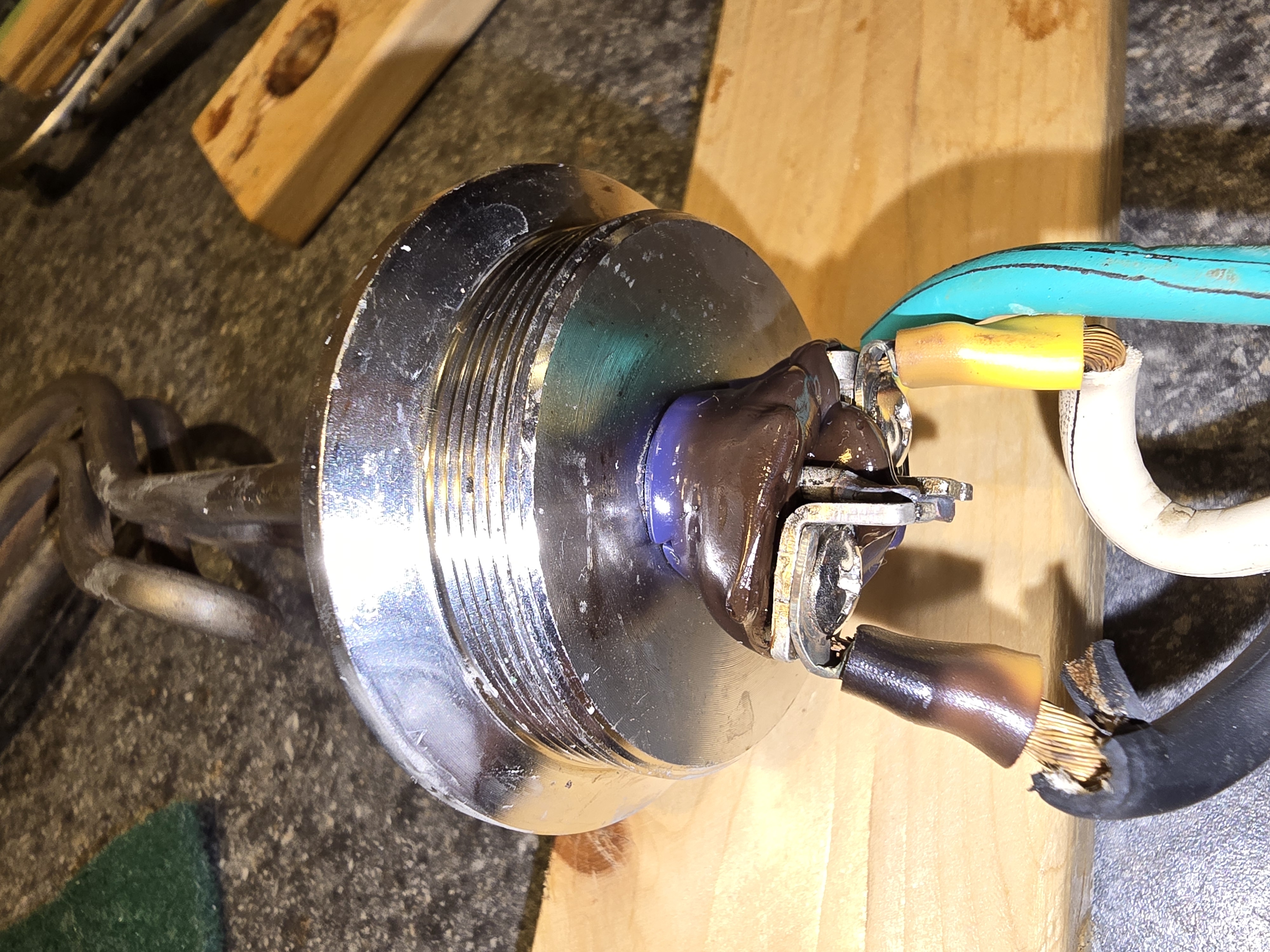
What you want to look at when it comes to localized heating is this formula: P = R * I^2, where P is power. Since the current flowing in any branch of a circuit is constant everywhere, you can break the circuit branch into individual pieces, each with their own resistance value. The heat generated in each of the pieces is then determined by the current and the resistance of the particular piece.

Let's look at a simple example:

The fixed voltage is 240V, and the branch of interest is two connections with a nominal resistance of 0.005 ohm (5 mohm) each and a heating element with a resistance of 10.30 ohms. The total resistance of the branch is 10.31 ohms, and the current flowing will be 240 / 10.31 = 23.28 A. Now, if one of the connections goes bad, and the connection resistance increases to 1.0 ohm, then the branch resistance increases to 11.305 ohms, and the current drops to 240 / 11.305 = 21.23 A. For the original connection, the heat generated in the connection will be 0.005 * 23.28^2 = 2.71 W. For the degraded connection, the heat generated will be 1.0 * 21.23^2 = 450.7 W, which is more than enough to overheat a small volume and burn the insulation.

Brew on :mug:
I stand corrected! You are right. Where I worked before retirement we had power supplies that were Constant voltage output (120-165 Kv) and monitored the final output. If the output (photons) dropped the feedback would increase the current. So a resistive connection would just keep getting hotter and hotter. Sometimes I can't get my brain out of work mode and back to the theory mode.
Thanks for catching that.
 
7xda6u-2549655433.jpg
 
Yes... and 10ga. is rather easier to work with than 8ga. Heavy enough wire is crucial, but issues at the connection points seem to make the most trouble for electric brewers.
Yes! My BK element is in the process of getting replace today. It didn't stop working but could only get 12 gallons of water to 200 degrees.
In the past it was fast and I got a hard boil around 208 degrees. Even 8ga. can fail if the operator selects the wrong tank. BK is not my HLT. $65. dollar oops!
 

Attachments

  • 5500 element fail.jpg
    5500 element fail.jpg
    2.7 MB
People are switching from screw tightened connectors, to spring tightened ones.
When a wire, or terminal, connection is tightened with a screw. Initially there will be a good contact. But when soft metals, such as copper, deform under the tightening load, it means the connector will need to be re-tightened.
Spring loaded connectors, such as WAGO, will still maintain a good contact, if the junction metal deforms.

There's Wago PCB terminal blocks now.

Where screw tightened connectors are the only option, it's important to re-tighten after maybe one month, and one year.
 
@KyBeer posted a picture of what looks like an element with a melted plastic insulating base where the terminals are mounted. Something clearly went wrong there, but what exactly? That, and the reminder from @hungupdown about verifying connections are tight, motivated me to check mine.

Almost all use lugs on the wire, like KyBeer's. They were all still very tight. Only those on copper could be tightened further. But wait, there's more!

I noticed the lug sleeves in KyBeer's pic were quite discolored - no surprise, if things were hot enough to melt the element's plastic and turn it brown instead of the original blue/purple visible to the left, if I'm seeing right.

The sleeves on my lugs look fine, EXCEPT those on my BK element. (HLT never runs close to boil.) The BK element lug sleeves look baked, though the element body and wire insulation looks just fine. I haven't seen this before. Is it normal?? If so, I'm inclined to remove those useless sleeves. If not, I may need to reconsider these lugs altogether.-------------------------------------*
ugly_lugs.jpg
 
I suggest the heat discoloration could be two fold.

The terminal hole size is too big relative to the screw size, and it's possible the crimp of the terminal on the wires themselves is not a good, high compression crimp.
 
Last edited:
Even 8ga. can fail if the operator selects the wrong tank. BK is not my HLT.

If your control panel/system allows the operator to select a setting that will cause damage to the system, then that is a bad design. There should be no operator switch selections that allow damage to the system if a simple mistake is made. At a minimum, a controller should be designed to prevent easy to make mistakes.

Brew on :mug:
 
I suggest the heat discoloration could be two fold.

The terminal hole size is too big relative to the screw size, and it's possible the crimp of the terminal on the wires themselves is not a good, high compression crimp.
Thank you. I've ordered some new lugs. In lieu of a (dubious) crimp, I plan to solder. I may add washers to increase contact between lug and screw terminal, if the hole size remains so mismatched.
 
unlikely to ever accept WAGOs
I haven't seen or even heard of these. Springs? Tight enough? Really? Is this basically a lock washer for electrical connections?

The solid copper in my HLT did allow a bit of tightening. I guess I'll check it again next time I see another HBT post with a picture of melted stuff.
 
Crimps have the problem of looking really simple to the average DIYer but it has to be crimped ideally to keep the resistance to a minimum. One thing I didn't realize for a while was that there is a different tool design for insulated vs. non insulated crimps.

On something like the Klein combo cutter/crimper, the red dot is where you put the insulated connectors and the blue dot is where you put the uninsulated. The pointed part goes against the smooth side of the loop, not where the split is.
1751549849181.png


On more discrete crimpers, the dies are completely different.

1751549727807.png
1751549665484.png
 
I have a number of different crimpers for various terminals.

This Molex is one recently acquired and is a full cycle crimper. More $$ than your average pliers-type crimper but in the big world of crimpers it's not a huge outlay at about $80.

Also have a similar style for 3M terminals but that crimper is way more expensive.

20250703_080829.jpg


Thing is though, to get the right crimps you also need to use the correct series of wire terminals for the crimper.

With that specific Molex crimper I use Molex AviKrimp (my preference) or alternately Molex InsulKrimp terminals. They are a "match" to tge dies and compression of that crimper.

It crimps not only the terminal barrel, but also the insulation support as shown above in one of the pictures Bobby posted.
 
it has to be crimped ideally

need to use the correct series of wire terminals for the crimper

Got it. For me, this is a strong argument for soldering the lugs onto the wires. Inadequate crimp may well explain the overheating shown in my post #45 above.

My intuition tells me a soldered joint should minimize resistance better than any crimp. Intuition is often wrong, though...
 
My intuition tells me a soldered joint should minimize resistance better than any crimp. Intuition is often wrong, though...

There will be difference of opinion but a soldered joint is not always, and maybe not even usually, better than a proper crimp. Proper being the key operative. I've seen some really crappy solder joints maybe as much or more than crimps.

Personally I very rarely, almost never, solder crimp type terminals. My soldering is normally only for circuit board and or point-to-point type circuits.
 
I guess I'd rather a good solder joint to a poor crimp or a good crimp rather than a poor solder joint. I dip the stripped strands into flux and pre-tin the bundle. Then dip the crimp into flux, insert the wire bundle and heat it all. Here's the rub. Flux is corrosive. The reason it does its job is that breaks through the oxide layer of the materials so that the solder can wet the metal. If you leave the flux anywhere, it will make things worse.

Unsolicited story;
Just out of high school I had a job assembling amplifier modules for microwave radios (the big towers on mountain tops)..The circuit boards were bed soldered to aluminum heat sinks and then I'd hand solder 150 surface mount components about the size of short grain rice onto the board with magnifying goggles on. The whole board would be drenched in flux residue so I spent an HOUR per unit scrubbing out the flux with various brushes, Dawn dish soap and blazing hot water. I don't know if that was the best way, but that's what the PHD guy that quit Bell Labs told me to do.

Long story short, wash the joint well and then use heat shrink if you need to insulate.
My method was to sprinkle dry unscented laudry detergent over the board, scrub it into the flux residue with a toothbrush and then rinse the whole thing with warm distilled water while using a clean toothbrush to make sure everything rinsed off....sometimes took 2 goes and an extra toothbrush.
 
Circuit boards are a different matter.

The only "reason" to solder crimp on wire terminals is to band aid a crappy crimp job. Just cut to the chase and do the crimp right and you don't have to do all the soldering futz.
 
Yeah... you'd never want to use acid flux, per se, on wiring connections.

There are many different fluxes available and 60/40 or 63/37 general electrical/electronics solder types with varying degrees of flux agressiveness and some "no clean" varieties that many still clean. :)

Well off on a tangent now...
 
If I absolutely had to solder a high-current connection, I'd use the quad-eutectic solder and rosin from Cardas...Hey: It's made in the USA so there's no iffy chemistry or metallurg.....I don't usually solder crimps though when I have the properly spec'd crimping parts to hand.....just sayin'
:mug:
https://www.cardas.com/supplies
IMG_1801.jpg
 
In my job before retirement I worked with 120Kv and 700 amp equipment. All the connections mechanical. The connectors and wire were rated 200% of the expected load. Tried to carry that practice into the build of my brew system. If 10 awg was the minium gage then 8 awg is what I tried to use.
 
I don't oversize simply for oversize sake but if all I have is oversize I'll use it, so long as it's not too cumbersome or impractical to use it.
 
Has anyone measured a heating coil resistance to ground? I posted a picture of my damaged / weak element. I over heated the element by selecting the wrong kettle. By the time I could smell the heat the element was red hot. I let it cool and the next brew was a small 5 gallon beer and it seemed to be fine. The next beer required a 12 gallon boil. It only made it to 200 degrees. I suspected the element was damaged. I replaced the burned connecters and cutback the cable a bit. Same results.
I ordered a new element. I always chek the resistance prior to installation. Both elements measure about 10 ohms as expected. A check of the element to the ground on the old element show open as it should. The new element measures like a cap. It starts around 18 meg and climbs.
Strange!
 

Attachments

  • 5500 element fail.jpg
    5500 element fail.jpg
    2.7 MB
I suggest the heat discoloration could be two fold.

The terminal hole size is too big relative to the screw size, and it's possible the crimp of the terminal on the wires themselves is not a good, high compression crimp.
If the crimp terminal was copper, it should have at least the same cross sectional area as the cable connected.
But often it seems to be much less.
And as terminals are usually tin plated steel, the cross sectional area actually needs to be bigger.
 
Personally, I don't run into too many steel terminals other than in some cases where they are uninsulated, nickel-plated steel for high temp use.

The nice thing about using big names like Molex et al is if you dig enough one can usually find detail datasheets that give current ratings for the various styles and sizes.
 
G
At what wire gauge do you switch over to hydraulic crimping?

Brew on :mug:
Greater than 10 since 10-12 insulated terminals are the largest rated size for the full cycle crimpers I have.

Last project for the hydraulic crimper was 6ga for 210Ah battery I assembled from "lithium" prismatic cells. These are uninsulated terminals but heat shrinked over the barrels and a bit over the cable jacket.
 

Latest posts

Back
Top