Awesome! I'm really interested in your build and how things turn out for you. As you know, I'm in your corner cheering you on.My enclosure is ready to be milled for the hole layout now! ...
Paul

Awesome! I'm really interested in your build and how things turn out for you. As you know, I'm in your corner cheering you on.My enclosure is ready to be milled for the hole layout now! ...
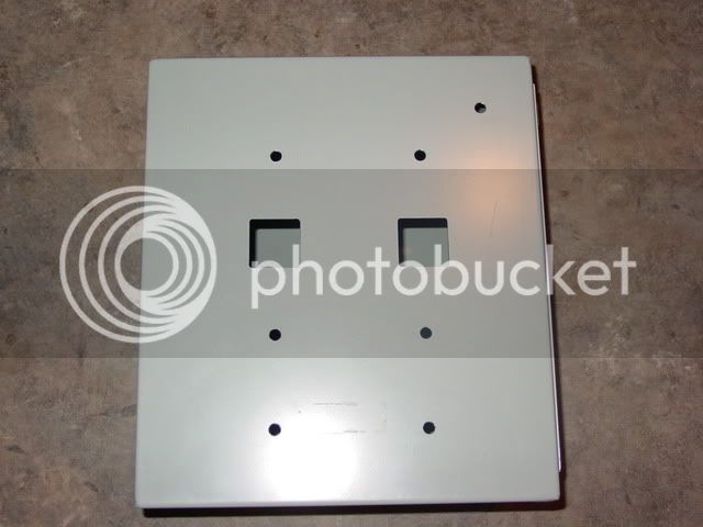
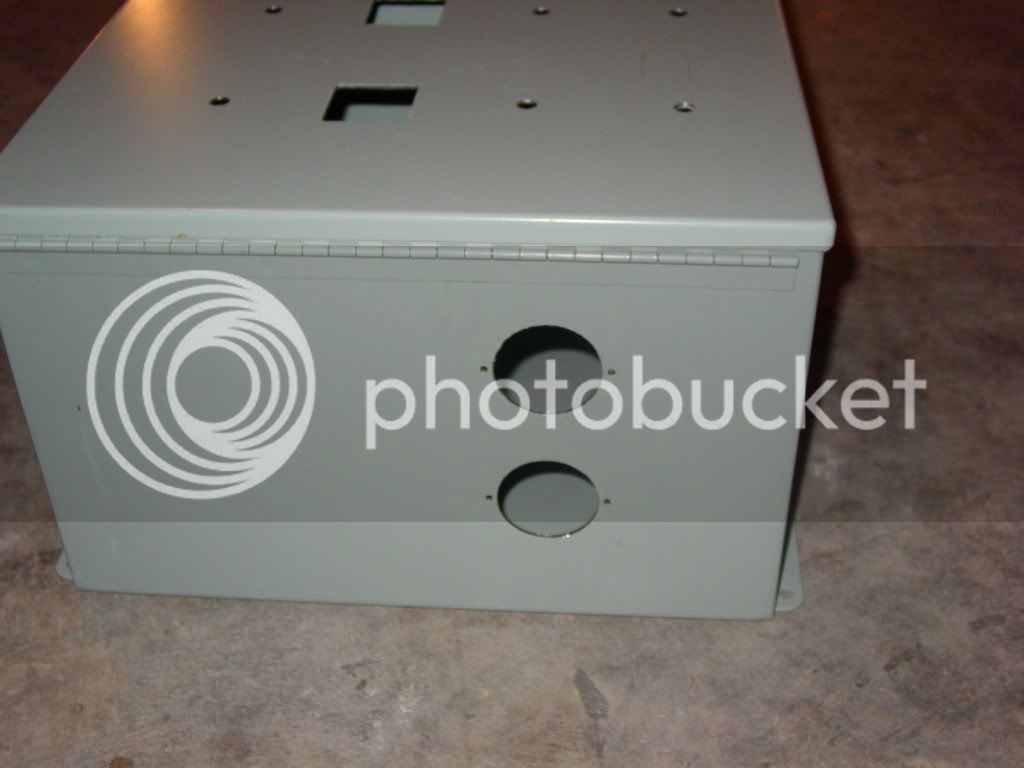
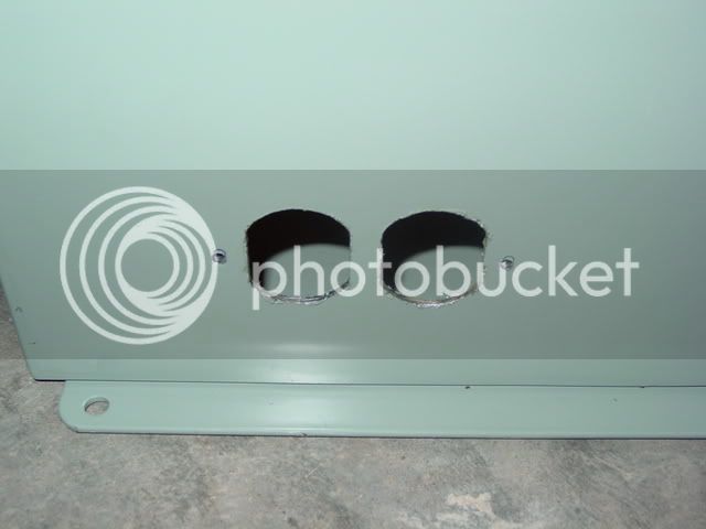
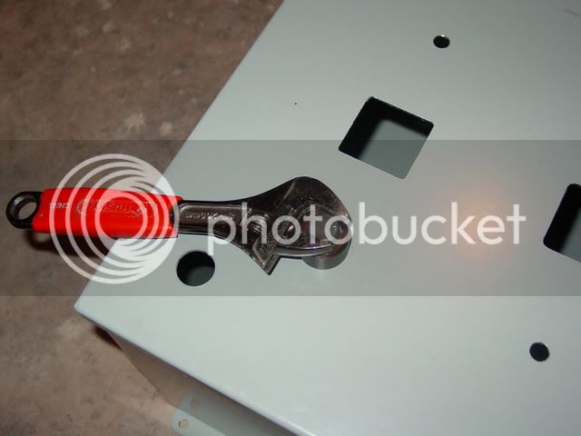
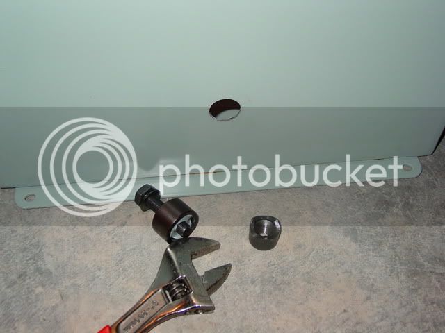
We milled out my enclosure today!
I didn't take any pictures of the process, but we had fun doing it. Took about 4 hours with plenty of BS-ing and taking our time.
I'll take some pictures of the milled box and post 'em up when I get a chance.
TB
This link will take you to an excellent wire gage chart: cerrowire.com
If you intend to use crimp on connectors, solder the crimped connection after crimping. This is important on the high current lines (heating element connections for example). Trust me on this one, it will save you a lot of grief down the road.
I don't mean to come across in a negative way, but you throw out a bit of info and then say don't ask.I've done some marine wiring and you can do either soldering or crimping but NEVER combine them. I thought is was a great combination as all marine wiring comes tinned, but in fact it will make the connection weaker. Don't ask me for the details at this moment but if have seen the guidelines from the connectors years ago.


Walker (if you're still here), how did you run your TC or RTD wires through your enclosure? Do you have any pictures of that?
Thanks,
TB

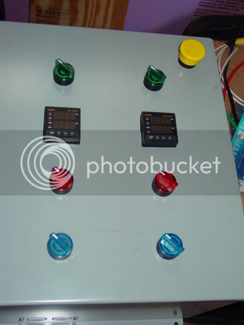
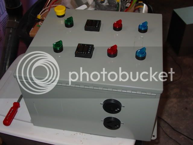
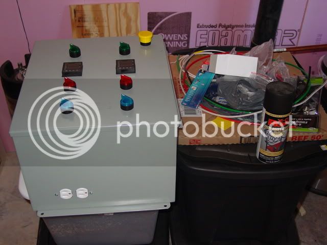
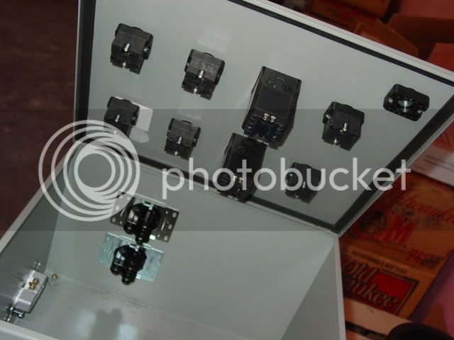
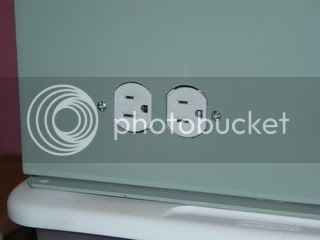
i have the exact same box as you. pretty much identical. i just got mine all wired up and water tested last night for leaks. what i did was install those omega panel mounts from auber. i used tc's instead of rtd's tho. I mounted the omega's right above the 240 outlets.
i mean i was testing the box to make sure everything works. i was water testing the pots to check for leaks. i built the same thing that you are building.
http://yfrog.com/3d0821001437aj
http://yfrog.com/n90821001437j
http://yfrog.com/my0821001438j
http://yfrog.com/6z0821001435aj
http://yfrog.com/mr0821001435j
http://yfrog.com/j00821001434aj
http://yfrog.com/9d0821001434j
sorry for the links. didn't have another way to get them to you without email.
rian
Looking good!
Thanks, bro! How's the brew space coming along?
sick sick sick!!!!
Do you think you could pull that off with a 12x12x8 electrical enclosure??
Thanks!

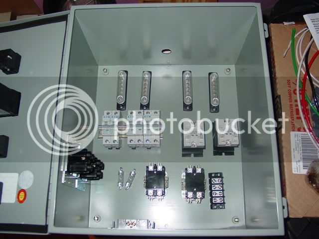
I think that's possible. If you don't have 4 SSRs in it, and you use DIN mount components, you shouldn't have a problem with that. Mine is 10" deep, so yours would only be a couple inches shy of that, which I don't think would cause any problems. I've got plenty of real estate on the front panel, too, so I'm sure you could consolidate your switches with a little more care for surface area than I did.
I gotta say, though, it's nice working with all this room.
TB
i was water testing the pots. i used the diagram that p-j made for you on this thread. works wonderful!! it took no time. 4 ssrs would fit no problem.
gabrew you check out ebay? i got my box from weaver electric. it was 20 i think with 20 shipping. if you do ask for a backplate. made installing a breeze.
i was water testing the pots.


![Craft A Brew - Safale BE-256 Yeast - Fermentis - Belgian Ale Dry Yeast - For Belgian & Strong Ales - Ingredients for Home Brewing - Beer Making Supplies - [3 Pack]](https://m.media-amazon.com/images/I/51bcKEwQmWL._SL500_.jpg)


