OP
OP
Thanks PJ...this looks great!
Tiber, what are those style of switches called? Thanks.
I'm using illuminated selector switches such as this one.

Thanks PJ...this looks great!
Tiber, what are those style of switches called? Thanks.
This link will take you to an excellent wire gage chart: cerrowire.comFor wiring the enclosure, what wire will I need and how much of it? Does anyone have a good way to estimate that?
I'm going to Lowe's this weekend and will hopefully pick up some much needed parts for my project while I'm there.
Keep in mind the nearest Lowe's is 100 miles away. This is a big deal for me -like a kid in a playground!
This link will take you to an excellent wire gage chart: cerrowire.com
For the circuits before the breakers the wire needs to be rated for 50 amps (the value of your mains breaker). You can use #8 THW/THWN or you can just use some of the wire (a foot or two) from your power cord.
The wiring after your breakers should be sized for the breaker value. #14 wire for the 15 amp breakers, # 10 for the 25 amp breakers.
I think you would only need 3 or 4 feet of each type and color. I suggest that you use stranded wire instead of solid copper as it is more flexible. Another thought for you. If you intend to use crimp on connectors, solder the crimped connection after crimping. This is important on the high current lines (heating element connections for example). Trust me on this one, it will save you a lot of grief down the road.
Hope this helps.
Yes.! I wish I lived closer to you. The wiring would be completed now.any updates?
")


Another thought for you. If you intend to use crimp on connectors, solder the crimped connection after crimping. This is important on the high current lines (heating element connections for example). Trust me on this one, it will save you a lot of grief down the road.
any updates?
Yes.! I wish I lived closer to you. The wiring would be completed now.
I'd really like to talk with you on your progress. I think you are going to have an awesome system.... I'm anxious to get back to this project, so I will be giving P-J another call soon and taking more pictures as I go.
Isle Royale? You're forgiven.

I'd really like to talk with you on your progress. I think you are going to have an awesome system.
Thanks for the update.
 Not used to takin more from the table than I bring.
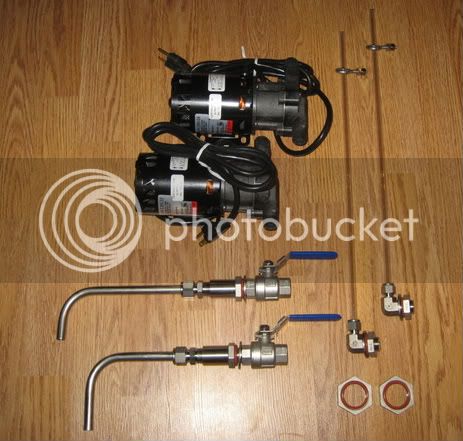
Holy Cow, this is EXACTLY what I need!
Only difference is I will run a 2000w RIMS in my MT. I assume thats not difficult to add?
What an awesome thread. Thanks for sharing your time and knowlage guys.
I'm a firm believer in the 'Pay it forward' theme. But, I'm workin from a pretty big deficit on here.


The PIDs use temperature sensors that are places in the kettles. The sensors can be mounted differently depending on your choices. In the systems that I've built, I use thermal wells.Ok, how does the PID get the actual temp reading. Am I missing something?
The PID temp probe info is illustrated on the PID diagram:My 'RIMS in a toolbox' is set up that way, but I did not see it in the schematic in this thread.
Or did I overlook something? Electronics is not my strong suit.


![Craft A Brew - Safale BE-256 Yeast - Fermentis - Belgian Ale Dry Yeast - For Belgian & Strong Ales - Ingredients for Home Brewing - Beer Making Supplies - [3 Pack]](https://m.media-amazon.com/images/I/51bcKEwQmWL._SL500_.jpg)


