rycov
Well-Known Member
also anyone looking at this, don't take this to be correct. i'm asking the more knoledgable people if it is right. so untill some one gives it the ok, don't use it.

also anyone looking at this, don't take this to be correct. i'm asking the more knoledgable people if it is right. so untill some one gives it the ok, don't use it.

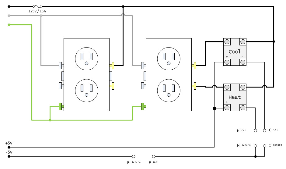

ok. i think i get what you have goin on there, but bear with me. i'm really not an electronics guy. what is the outlet on the left for? it looks like your going to plug the fridge and heater in on the outlet to the right? also as for how it is linked to the thermostat, mine says Rh, Rc, Y, G, and W. do you know how that corresponds to your: H out, H return, C out, C return, F out, F return? i'm trying really hard to understand this stuff and i think i almost got it. thanks jmferris!


so the the Rh and Rc would be going from the thermostat and to their respective relays? and i wouldnt want them to be jumped so i could control them individually? or its the power coming from the transformer and i would want them jumped so they both get power? then wich ones would go out from the thermostat to the relays? and if i didnt wire two outlets like jmferris then i could just plug the transformer into the wall right?
I think this will work: Referencing the diagram in post #63 - H out would be "W", C out would be "Y" on the 'stat. Leave Rh & Rc strapped together & run to the -5volt supply (Fan, that is "G" on the 'stat) is not needed.
also please post some pictures when you get it done!
ok. another dumb question from my non-electricity understanding ass. i bought two relays. figured i needed the DPDT the one i got is eight pin. is this right? after reading a bit on relays it seems like i should have gone with the SPDT. i went to radio shack and they didn't have any that looked like the ones from the OP. please help!
and jmferris, don't forget about the update pics!

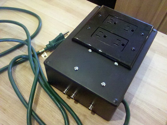
ok. so what i want to do is connect the bottom two, that are turned perpendicular to the others, to the thermostat and transformer, then connect the wires from the wall to the outlet through two of the other poles? does it matter which ones i use? also it looks kinda little to be running 120 volts through.
please let me know if this looks right
ok. i think i see what your saying. sorry for all the questions. i really have know idea what i'm doing. but i can test it with something else, like a speaker, or a small light bulb or something?


![Craft A Brew - Safale BE-256 Yeast - Fermentis - Belgian Ale Dry Yeast - For Belgian & Strong Ales - Ingredients for Home Brewing - Beer Making Supplies - [3 Pack]](https://m.media-amazon.com/images/I/51bcKEwQmWL._SL500_.jpg)


