• Please visit and share your knowledge at our sister communities:
  • If you have not, please join our official Homebrewing Facebook Group!

    Homebrewing Facebook Group

Control Products Dual Relay $60 Shipped on Amazon

Homebrew Talk

Help Support Homebrew Talk:

This site may earn a commission from merchant affiliate links, including eBay, Amazon, and others.
I built out one of these this weekend. I'm an electrical noob as well, but I got it working and tested successfully without frying myself, lol. I followed CPs diagram and the diagrams posted in this thread, and pigtailed everything. It's a tight fit in the box, but it's working as advertised.

IMAG0040.jpg


IMAG0049.jpg
 
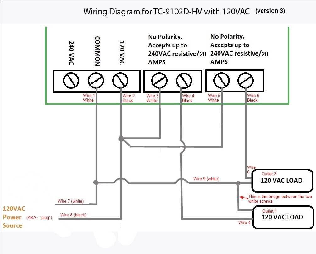
Land o Lincoln, you might want to take down your first drawing where you're switching the white wire. It's a pretty big safety hazard to switch the neutral!

Also, in the second drawing, you don't need the wire if you leave the tab on the white side of the receptacle. If you've broken the tab you can just put a wire between the screws and be fine.

1) Yes, good idea. I'll edit my previous posts.
2) That's what I was thinking. I'll do that.
 
scaled.php


scaled.php


And that should do it. Tested it out with the outlet tester and the wiring checks out. Good job, me. And thanks to everybody else that told me how I did it wrong.

This is a nice controller. I'm glad I got it.
 
scaled.php


scaled.php


And that should do it. Tested it out with the outlet tester and the wiring checks out. Good job, me. And thanks to everybody else that told me how I did it wrong.

This is a nice controller. I'm glad I got it.

So you switched the power leg around? Did this new setup take care of your "open neutral" issue?
 
^ nice job. What's nice is you learn something new on projects like this and feel comfortable repairing and tweaking now too.

1 tip going forward is that when you are working electrical it really helps to use the correct colored wires just to keep things straight. If you buy a small roll of 14 guage electrical wire you can strip out sections of white/black/ground to use. Using solid wire instead of the stranded mess really cleans up connections and makes them safer. Pigtails and wirenuts make things a lot easier.

2449910.jpg


2008-02-13_212731_wirenutR.jpg
 
Awesome, thanks LandoLincoln et. all! I'll also give this a shot soon.

:mug:
 
nice pics, might be doing something like this very soon. This should be a great help! :mug:
 
An update, after a few stops and starts (note to self: 20 AMP extension cord is very different than 15 AMP cord; 12 AWG wire is not easy to bend, etc.) I got it running today. I'm so excited, this was my first real electronic project.

Lincoln et. all, thanks so much! Your patience with someone as new to this type of project as I am is greatly appreciated. :mug:

Now to play around with it...

temp.jpg


temp2.jpg


temp3.jpg
 
Wiring up this bad boy thanks to everyone's help, but I have a few questions.

1. Has anyone extended the sensor lead? Did you just use 26 AWG wire? Where'd you get a short length?

2. Is it ok to just use a 14 AWG appliance cord (flat) to provide power? Seems like everyone was using generic round black extension cords

Thanks for your help guys!
 
Thanks for all the info guys!

I had an old Johnson mechanical unit that bit the dust recently and this controller is the ideal replacement. I got it working over last weekend with Lando's modified wiring diagram, and drac0's part list from this thread https://www.homebrewtalk.com/f51/chest-freezer-fermentation-chamber-268999/index4.html.

There was some question as to extending the sensor lead. The PTC sensor that it ships with can be extended to 100' according to the manufacturer's web site. http://www.controlproductsonline.com/temperature-sensor-302degf-p-62-l-en.html I used a good pair of 24 AGW wires out of an otherwise damaged piece of CAT5 network cable to do so.

Also, make sure to read the manual and check the sensor for accuracy. I had to adjust the calibration on mine by 2 degrees.


Cheers! :mug:
 
I'm considering getting one of these but I'm a total noob at dealing with electrical wiring. I was looking at the manufacturer's website and was wondering why you guys didn't mimic their diagram. http://www.protectedhome.com/documents/TC9102DHV 120 VAC Wiring Diagram.pdf

Any other help is appreciated. I'd like to get this one, but I keep wavering because I'm not confident with electricity. It kills!

Their wiring diagram wasn't that helpful to me, and using their diagram I didn't wire it right. Maybe the problem is mine, I don't know. But the way I wired it is the same way that the other guys that use the ebay aquarium temp controller wire theirs, and mine has been working just fine for the past few months.

Don't be afraid of this electrical project. It's not that complicated once you get into it.
 
I've wired one of these up and want to configure it to keep a fridge at a set temp.

I've successfully turned off relay2 which I won't be using, but I could really use some help figuring out how Set Point1, High Set Point1, Low Set Point1 work.

I can set the values but I don't understand how they work together.

Could someone post an example to help get me started?

To keep the fridge at 45 degrees:
SP1 = ___
HSP1 = ___
LSP1 = ___

Thanks!

The HSL (high side limit) and LSL (low side limit) don't do anything to the temperature. The HSL and LSL function is there to constrain your choices to a certain range. This is useful if some doofus comes along and tries to set the unit too high or too low. But since you're probably going to be the only doofus using this unit, it's okay to bypass this safety feature.

I set my HSL to 90° (which is higher than I'll ever go) and my LSL to 30° (which is lower than I'll ever go).

SP1 would be set to the "COOL" function.

Let's assume your stage 1 differential (df1) is set to 3° (which is the default), then the unit will turn on SP1 when the temp reaches 3° above whatever you set, and then will cool it down to the set point.

So if you want temps to stay in the 42° to 45° range, set the SP1 to 42°.

If that is too wide of a temperature range, you're going to have to lessen the differential to something less than 3. Doing this is going to kick your compressor on more frequently, though, and that will shorten the life of the compressor.
 
To the OP, I checked one of these out, the wiring isn't too hard, but the incremental cost between this and a wired Johnson control is, like, $25. I think for the cost of the cord ($8-$12) and the aggravation, I'd just buy that. If you got it on Amazon returns are pretty easy.
 
Ok well I'm a moron and didn't notice this was from like 8 months ago. FTW!
 
Quick question, I miswired this and threw a breaker.....now whenever I use it...even though Stage 1 shows off, it is powered and Stage 2 is regulated properly.

I wired it per this post after I threw the breaker....is it possible to burn out the Stage and cause it to be always on or is this most likely a wiring issue?

Thanks,

Pat
 
I'm not an electrician but I don't think it's possible to "burn out" a relay and cause it to be on all the time. If anything, it would never turn on. I would guess it is a wiring issue.

I just wired mine up and after looking at the diagram on the website. the relay switches the ground, not the hot wire. If you are wiring from an AC power cord, the white one is patched into the relay and the black is put directly to the outlet (that the fridge or heater is plugged into).

All in all, pretty easy to wire this - certainly no more difficult than the ranco unit. I did the same thing as an earlier poster with an outlet that I broke the bridge clip on. I have a tiny space heater (that sits inside the chest freezer) plugged into the top outlet and the chest freezer plugged into the bottom outlet.
 
That is wrong, and totally unsafe.

You never want to leave the 'hot' wire on all the time. The hot wire should be switched by the relay.

If you wired yours with the hot on all the time you should rewire it correctly.

B
 
bad coffee said:
That is wrong, and totally unsafe.

You never want to leave the 'hot' wire on all the time. The hot wire should be switched by the relay.

If you wired yours with the hot on all the time you should rewire it correctly.

B

I'm not generally one to post just to add a +1, but it is warranted here. This is very dangerous for a variety of reasons, not the least of which is that if someone sees the light off in the fridge (or it won't kick on), they may assume that no power is being delivered to the device or the receptacle when it will in fact be live all the time.

I have both been shocked and had a small fire because a previous homeowner wired circuits this way.

Adam
 
Big thanks to Landoflincoln and others who contributed to this post. I wired mine up last night and it works flawlessly. Thanks guys.
 
Just bought two of these for two 14.8 cf freezers for my garage here in the Chicago area. I work with electrical all the time in my decorating business so i have outlets, boxes, 14 & 12 solid wire, caps and all lying around so this looks like a no brainer to me. Most important is everyone seems quite happy with the results after its assembled.

Whats the best option for the heating element? I assume 14 gauge wire is good for the heater if its only a 4 foot run. Just drop it in the back hinge side between the weather strip like the thermometer?

I believe 14 gauge wire is rated for 15 amps, so yeah, any little heater isn't going to draw more than 4 or 5 amps. But check the unit in question to be sure.
 
Take a look at the STC-1000 build threads. They are actually very easy to assemble and operate. I built one into a 2 outlet old work blue plastic box and it works great for running the fridge and heat wraps. They are actually very easy to build and get working properly. I can keep my lager temps at around 45 degrees in the Fla summer heat pretty easilly. I am using a dorm frige made into a blue board chamber and the larger volume makes it a little slower cooling, but once it gets there it maintains it extremely well. My total investment was less than 20 bucks for everything including the STC-1000, circuit box, outlet and cover. I already had a cord and wiring here, so I didnt have to buy any more stuff to get it to work great. Hope this helps to get you back on the path and going again.
Wheelchair Bob
 
Back
Top