• Please visit and share your knowledge at our sister communities:
  • If you have not, please join our official Homebrewing Facebook Group!

    Homebrewing Facebook Group

Contactor / SSD / Breaker Order

Homebrew Talk

Help Support Homebrew Talk:

This site may earn a commission from merchant affiliate links, including eBay, Amazon, and others.

audioa84

Well-Known Member
Joined
Jan 25, 2016
Messages
57
Reaction score
41
Location
KC Area
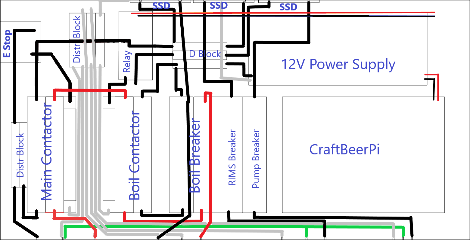
Hello All. I'm putting together a controller that has relays, SSDs and contactors in it. From the diagrams I'm seeing online, most have the power going from source -> main contactor -> breaker -> SSD -> secondary contactor -> plug. Is there any harm in having the breaker, SSD & secondary contactor in a different order? The image shown below had my intended orientation as it reduces the number of times wires crossed so that the mounting plate would fit better. This is all powered off a dedicated circuit with a 240v 30A GFCI breaker.

Thank you for any advice given.
 

Attachments

  • brewing controller layout.png
    brewing controller layout.png
    89.6 KB
That diagram is pretty much unreadable.

In my designs, I go power input -> main power contactor -> optional breakers/fuses -> element enable contactor -> SSR -> element. I like to put the element enable contactor upstream of the SSR as it removes power from more of the circuitry when off. I never understood why so many designers chose to put the SSR upstream of the element enable contactor.

Breakers/fuses in the high current path are only necessary if you are reducing the wire size along the path - as when going from a 50A w/8AWG input down to a couple of 30A paths w/10AWG wire. Otherwise, you are protected by the source power breaker.

Here's some designs that show how I do things:

DSPR300 1-Pump 1-Element 240V rev-2.PNG

KKBrew-corrected.PNG


Brew on :mug:
 
@doug293cz Thank you. This was exactly what I needed. I agree that my diagram is extremely rudimentary. I looked for design software like what you must have used above but struggled to find one for the hobbyist. I will take what you have said above into account. Cheers :mug:
 
Here's something scraped out of my records. I've cut out near enough everything but the component you've asked for. There's nothing that's different to @doug293cz has put, but you might appreciate a second view:

1728573218799.png


I never thought I might post any electrical stuff; being a Brit, we may do things differently with electrics. But I was surprised seeing this query with its references to "contactors". When I was designing my control boxes they were based on the American "Electric Brewery" docs as is commonly used over here, but it has no "contactors". As a result, there were loads of UK brewers searching for 32A releys. I think 8A was the biggest over here. In our little crowded space 32A basic relays sparking about the place would ensure no-one could watch television or listen to radio over all the spark induced interferance. So in the UK it was contactors or nothing.

The Chinese ensured the impoverished Brits weren't left with nothing! Hence we have sparkling 32A relays now! (Oh dear!).

Anyway, that's by the way. You were looking for design software. The above was created in Microsoft Visio, but I'm sure the freebie LibraOffice Draw can do the same thing. They are drawing packages, not electrical design packages, but that shouldn't be a handicap.
 

Latest posts

Back
Top