BruControl: Brewery control & automation software

Homebrew Talk - Beer, Wine, Mead, & Cider Brewing Discussion Forum

Help Support Homebrew Talk - Beer, Wine, Mead, & Cider Brewing Discussion Forum:

This site may earn a commission from merchant affiliate links, including eBay, Amazon, and others.
Thank you for the information, I'll remake it with the minimum length shielded cable and check the connections again.
If no joy I'll replace with ntc 100k which is an alternative. I don't suppose that I can add a resistor somehow to my many spare ntc 10k sensors to make it 100k?
Further question I had the recognised melt of my Fotek, probably due to bad positioning as the side that melted was close to the upper edge of the space it was in . It was still working.
I ordered a proper one pictured below but it didn't work when wired in. I have contacted supplier but wondered if I can test it in any way with a multimeter ?
Brewday was salvaged by bailing out the brew system and replacing the non working new one with the old melted one.
This was mounted out of the prior box, with proper heat transfer paste and a fan to cool the heatsink and coped with the brewday. ThanksView attachment 768462View attachment 768463View attachment 768464View attachment 768465View attachment 768466
Your controller needs to be compatible with DS18B20 or NTC sensors - they are not interchangeable. No you can’t add 90k to a 10k NTC sensors to make it 100k. You can but will get inaccurate readings.

FOTEK SSRs are notoriously fake and overheat. Could be internal or from resistance in the high voltage side terminal, but this looks internal. Also be careful of those heatsinks -‘they aren’t very flat so heat transfer suffers a bit. If the heatsink is really hot during operation, then it’s working ok.
 
@BrunDog
Thanks again. The controller accepts 2 wire NTC 100k or DSB1820 3 wire and then a menu selection so PID controller knows which one you have fitted.
Didn't really think that a bit more resistance would work.
I noticed the heatsink didn't give great contact on fit side so I used some thermal tape when I fitted it.
After I'd noticed the melting problem I noticed the packet said not for CPU or GPU use and it was only transferring 0.7 ( cant remember the units), changed to a silver filled heat paste for the refit / replacement saga and that was able to transmit 10x as much heat. With the added fan blowing cool air in and the heatsink attached to the metal body of the brew unit it should be a lot cooler. I have a replacement RS components SSR now on back order and will order a cheap ( likely fake ) fotek as a backup for the melted one/ swap over. RS components thought it could be a few months before stock arrived.
I declined a refund as likely when the stock arrives the price will have gone up by a margin the way things are going at the moment.
A 40A SSR is okay for a 3000w element on 240V at 50Hz ( checked the voltage and Hz the other day)? It's on a dedicated sole use 15A supply with 30 amp cable to RCD.
 
Returning to the PID questions. Thanks @clearwaterbrewer for the info. I have had some success this week and now have a couple PID loops working, although they are not ideal. I can set my sparge so that the HLT flow to the MT and the Wort flow to the BK are both set to 1gpm. I was able to get a PID working for my plate chiller to adjust flow to the fermentor based on chiller outlet temp. I have some ideas, but will need @BrunDog to validate my assumptions and ultimately it is likely feature requests to make this more robust.
1) like Swimlan, my PID parameters are very low for my proportional valve, like 0.4, 0.008 and 0.0008. Based on my tests, I believe that Brucontrol is using these low values. I can't manually enter 0.0008, but if I do it in a script, it will load it. When I adjust my "I" to something like 0.02, it does make a big difference. I had a great idea, what if you use the calibration feature in the PID device to scale it so you could use larger PID parameters? Well, this does not work. I am guessing the PID is working off of raw values. The target is the only thing that scales.
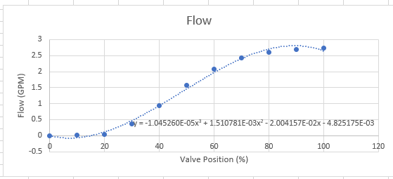
2) One of the things with PID's is they are assuming linear responses, meaning if you change a valve from 10% to 20% and the flow increase 1L/min, then you will also get a 1L/min increase if you go from 50% to 60%. This is not the case with my proportional valves as you can see by this graph.
1652462802312.png

I had another great idea, what if you use the calibration function in the PID device with a lookup table to make this linear? Well, this does not work for the same reason as above, the PID does not seem to be using calibrated values.
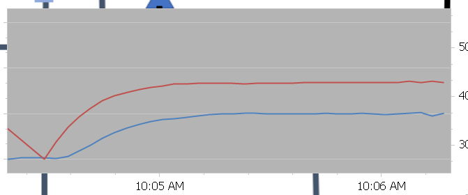
3) Here is a shot of my flow control. I am using a script to apply a deadband. Basically, when it gets within 0.1gpm of my target, I set the PID parameters to zero, effectively shutting off the control. If it drifts out of this deadband range, it loads the PID parameters back in. It is fairly slow, but fine for my needs. It takes 30-60seconds to stabilize. I was able to get this type of control for recirculation the mash and also for the sparge with two pumps and two proportional valves holding the same flowrate to keep the MT volume constant.
1652463459921.png

4) To my shock and pleasant surprise, I was able to get a PID working for my plate chiller on the first test, controlling the wort flow based on outlet temperature (I set the cold water manually and adjust the wort flow to get the correct temp). I didn't capture a graph, but I think this was pure luck as I guessed at parameters based on my sparge PID.

I think having the ability to calibrate the PID device and the input parameter and have PID control use the calibrated values would open up more possibilities for these devices to be robust.

Edited, tagged the wrong person above
 
Last edited:
Based on my tests, I believe that Brucontrol is using these low values. I can't manually enter 0.0008, but if I do it in a script, it will load it.
Interesting, I will have to try that... there is a debug you can use to have the interface spit out the PID component and total output values to the terminal every calculation period. This was how I eventually was able to see if it was actually incrementing the Ki value as time increased.
 
I am planning to add manual control of my propane solenoid valves.

Generally they will be controlled by a Mega 2560 on a Unishield. (Port 24 in the diagram)

In addition I want an Emergency Electrical Cutoff and a Total Manual way of opening the solenoid valves. I think I can do this with two maintained push button switches.
gas valves.png


I have these maintained push button switches that I want to use. In practice with just a power supply, the circuit seems to work (without the diode as I have not received them) logically.

Is putting a diode a good practice for not back feeding Port 24 (12 v output) on the Unishield?

is a 1N5406, 3A the correct type diode to use?
 
Very frustrating. Once again Elements are moving on their own. I was trying to edit a Script and had the script pane open. This seems to be a pattern when I have this issue. About 8 or so Elements moved seemingly on their own. Since some were stacked , it is a real PITA to get them back in position.

EDIT:

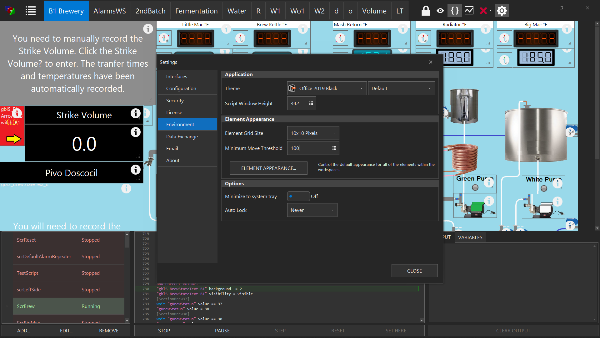
Setting the Minimum Move Distance in Environment Settings may help. It does without the Script Pane up and I will try to remember to set it to 100 when I am done moving things back.

enviroment.png
 
Last edited:
Returning to the PID questions. Thanks @clearwaterbrewer for the info. I have had some success this week and now have a couple PID loops working, although they are not ideal. I can set my sparge so that the HLT flow to the MT and the Wort flow to the BK are both set to 1gpm. I was able to get a PID working for my plate chiller to adjust flow to the fermentor based on chiller outlet temp. I have some ideas, but will need @BrunDog to validate my assumptions and ultimately it is likely feature requests to make this more robust.
@BrunDog can you unveil some mysteries behind how the pid is implemented in Brucontrol? What values is it using in the calculations for input and output variables? For example if I have two analog signals, is it using the 10 or 12 bit value? What about rtd's running on the digital bus? Is there anyway to condition/calibrate the signals prior to the calculations? This is needed to account for non linearity.
 
I am planning to add manual control of my propane solenoid valves.

Generally they will be controlled by a Mega 2560 on a Unishield. (Port 24 in the diagram)

In addition I want an Emergency Electrical Cutoff and a Total Manual way of opening the solenoid valves. I think I can do this with two maintained push button switches.View attachment 769629

I have these maintained push button switches that I want to use. In practice with just a power supply, the circuit seems to work (without the diode as I have not received them) logically.

Is putting a diode a good practice for not back feeding Port 24 (12 v output) on the Unishield?

is a 1N5406, 3A the correct type diode to use?
reboot. Trying to wire today.
 
I am planning to add manual control of my propane solenoid valves.

Generally they will be controlled by a Mega 2560 on a Unishield. (Port 24 in the diagram)

In addition I want an Emergency Electrical Cutoff and a Total Manual way of opening the solenoid valves. I think I can do this with two maintained push button switches.View attachment 769629

I have these maintained push button switches that I want to use. In practice with just a power supply, the circuit seems to work (without the diode as I have not received them) logically.

Is putting a diode a good practice for not back feeding Port 24 (12 v output) on the Unishield?

is a 1N5406, 3A the correct type diode to use?
First, sorry about the elements moving. I haven’t seen it myself so not sure how to replicate and solve it. I suggest keeping copies of your configuration in “good states” so you can revert easily. You can go backwards a day anytime as well.

Regarding applying voltage to a UniShield pin… fundamentally I disagree with the idea of adding manual controls to a digital control panel… complexity, fixed hardware, cost, wiring/hardware and debugging all counteract the software nature of these controls. That said, it’s your rig and you should be able to build it how you like! I honestly don’t know what would happen if you apply voltage to a UniShield driver pin. You can try the diode as a protection, but I can’t guarantee it will work. If you email us I can share the data sheet of the driver chips in case you can make sense of it!
 
@BrunDog can you unveil some mysteries behind how the pid is implemented in Brucontrol? What values is it using in the calculations for input and output variables? For example if I have two analog signals, is it using the 10 or 12 bit value? What about rtd's running on the digital bus? Is there anyway to condition/calibrate the signals prior to the calculations? This is needed to account for non linearity.
No mysteries…. It’s a straight PID calculation. I’m not sure your questions about the values it uses. I can tell you the calculation resolution is limited to 16 bits so some really wide ranges will get trimmed, but for brewing this should never be an issue.

If your analog input is 10 or 12 bit doesn’t matter - it will use that value. RTDs are the same way.

No, you can’t change the input values. Non-linearity shouldn’t matter that much. Remember that PIDs work on error calculations. P = error now, I = error over time, D = rate of change of the error. So every calculation cycle these three differences are calculated and added.

If the internal PID is returning unexpected results, debug mode will detail the individual calculations where you can see it in action. Alternatively, you can always script your own PID or other control algorithm.

If you need to solve a specific problem, I’m happy to connect with you via email or even phone if needed to get it right.
 
First, sorry about the elements moving. I haven’t seen it myself so not sure how to replicate and solve it. I suggest keeping copies of your configuration in “good states” so you can revert easily. You can go backwards a day anytime as well.

Regarding applying voltage to a UniShield pin… fundamentally I disagree with the idea of adding manual controls to a digital control panel… complexity, fixed hardware, cost, wiring/hardware and debugging all counteract the software nature of these controls. That said, it’s your rig and you should be able to build it how you like! I honestly don’t know what would happen if you apply voltage to a UniShield driver pin. You can try the diode as a protection, but I can’t guarantee it will work. If you email us I can share the data sheet of the driver chips in case you can make sense of it!
Thanks for the info.

I replaced the Diode with a 3 position Rotary Switch. I like to have manual control for my Pumps (easy to work with cavitation, and sometimes to manually flow from one vessel to another if there is an issue on a brew day that is outside of my planned day, such as Strike Water a couple of degrees low.)

I also like the same with my gas valves and ignitors.

I have already set up the pumps and ignitors and they are working well. I just wanted to have the same for the gas valves.

I did use Rotary Switches on the Pumps and Ignitors. Easy to do with the gas valves and no possibility of feedback.

I also use the Vessels and Burners for clean up which is a somewhat manual process as I let it do it cleaning while I am doing something else.

This is especially true when cleaning Kegs.

In addition, I might want to just heat some water (I use the HLT to supply hot water to an outdoor sink) on a non Brew Day.

So Brewing is normally using the automated system, but with a manual override for pumps when needed (transferring Wort from the Mash Tun to Brew Kettle or Wort to the Fermentor). I do have a button I can activate on the interface, but easier to tell a helper to "Turn off the Blue Pump!". I still have to click my button to advance the program, but I try NOT to touch my computer in a hurry when brewing. We also use a manual system to Vorluft the Mash Tun and the Brew Kettle before transferring. When we were using the BCS I found manual override and total Manual Control made hiccups much less of a problem.


In addition, we are a group and I am the only one that knows the Program and Interface. I am likely going to use a Digital Input via a Momentary Button to advance the program as well when a manual advance is required (like after a Wort transfer).

FYI, I have set the Move to 100 pixels and have not had an issue of moving Elements since. I am using the coordinates on the Appearance Pane to fine tune the x, y and w, h. I think part of the issue is when moving the mouse I got outside of the Script Pane and moved them inadvertently. When the Script Pane is open, grabbing an element that is partially blocked by the Script Pane moves differently than when the Script Pane is Closed.
 
No mysteries…. It’s a straight PID calculation. I’m not sure your questions about the values it uses. I can tell you the calculation resolution is limited to 16 bits so some really wide ranges will get trimmed, but for brewing this should never be an issue.

If your analog input is 10 or 12 bit doesn’t matter - it will use that value. RTDs are the same way.

No, you can’t change the input values. Non-linearity shouldn’t matter that much. Remember that PIDs work on error calculations. P = error now, I = error over time, D = rate of change of the error. So every calculation cycle these three differences are calculated and added.

If the internal PID is returning unexpected results, debug mode will detail the individual calculations where you can see it in action. Alternatively, you can always script your own PID or other control algorithm.

If you need to solve a specific problem, I’m happy to connect with you via email or even phone if needed to get it right.
PIDs assume linear response. The first 20% of the proportional valve shows no response and this will cause issues. Here is a reference that describes the issues I am seeing and I believe others have faced.
https://blog.incatools.com/pid-tuning-example-controller-nonlinear-response-valveMy question around values is just trying to understand what Brucontrol is using for calculations. Raw data, calibrated data, voltage? Is it normalized? I am happy to help run experiments and collect data. This seems to be a dissatisifier for many users that have switched from systems with pid controllers that work. I plan on doing some testing in the next week or so and will report back. If you have any other ideas on how to linearity the inputs, I would appreciate it.
 
PIDs calculate an output based on an input’s difference from a target. Linearity is not part of the calculation. That said, in your example, non-linearity is introduced through the downstream feedback loop, whereas the output (valve position) is not proportionally passed to the input (flow).

Bottom line… since this is a slow moving system and there should be no error offset over time, you may not need the I or D components. Since a straight proportional controller might not work, your best solution is probably to script the input/output directly.

For example, on my personal rig, I have a script running to handle electronic auto-sparging. The flowmeter reports input flow, and if the flow is above or below an acceptable window, it closes or opens the proportional valve respectively. This evaluation happens every 10 seconds or so, but certainly could be faster if the system response required it.
 
Ok, maybe you trust Wikipedia more?

PID controllers work best when the loop to be controlled is linear and symmetric. Thus, their performance in non-linear and asymmetric systems is degraded.

A non-linear valve, for instance, in a flow control application, will result in variable loop sensitivity, requiring dampened action to prevent instability. One solution is the use of the valve's non-linear characteristic in the control algorithm to compensate for this.
https://en.m.wikipedia.org/wiki/PID_controllerOf course you can do it in code, but that is not really the point of Brucontrol.
 
I think I know the answer to this, but is there anyway to send arguments to a subroutine, similar to how you would in most programming languages? I want to call the same subroutine with different parameters. If not, are there any cleaver ways to do this besides creating a bunch of temporary variables or creating multiple versions of the subroutine?
 
I think I know the answer to this, but is there anyway to send arguments to a subroutine, similar to how you would in most programming languages? I want to call the same subroutine with different parameters. If not, are there any cleaver ways to do this besides creating a bunch of temporary variables or creating multiple versions of the subroutine?
One issue with sub routines in a script is there is ONE return that is stored in the program. If you have multiple sub routines running, you may get an error. I call another script rather than a subroutine. I control flow with globals.

In general, I use globals versus variables because they can cross scripts. The only downside to globals is that are part of the data exchange and there is presently no way to "turn off" a global for data. I have so many globals that I cannot store data as It really slows down loading the program. Without data set up, literally seconds to load, With data set up, minutes. If I set up, my data files get humongous!

And for the most part, the data is worthless. I do not care for many Globals except maybe a few timers and temperatures. Any others are garbage from a data point of view.
 
Yes we will adjust this with Globals soon!
Please be able to not track period.
The ones that you do track have frequency option. My Mash I may want every minute, but fermentation maybe every 4 hours.

Be nice to force a one time read by script.
For example, I track how long it takes to transfer wort from the MLT to the Brew Kettle.
I also have globals that are Volumes that are manually entered (Mash, Sparge, Pre Boil, Post Boil, Dilution, Fermentor etc) that I want to capture, but just once on command.
Same is true for some Temperatures (Strike, Start of Mash)

I do this now but have to copy to a spread sheet after the brew
 
One issue with sub routines in a script is there is ONE return that is stored in the program. If you have multiple sub routines running, you may get an error. I call another script rather than a subroutine. I control flow with globals.

In general, I use globals versus variables because they can cross scripts. The only downside to globals is that are part of the data exchange and there is presently no way to "turn off" a global for data. I have so many globals that I cannot store data as It really slows down loading the program. Without data set up, literally seconds to load, With data set up, minutes. If I set up, my data files get humongous!

And for the most part, the data is worthless. I do not care for many Globals except maybe a few timers and temperatures. Any others are garbage from a data point of view.
Only one return in a script, or you can only call one subroutine at a time?
 
I am not sure how or why I got the errors when using subroutines. I was used to other programming that you could use multiple subroutines. I keep getting some error about "Return not Found" or something like it. I just went and started other scripts that set a Global Value as a way of returning to the calling script.
I suppose if you only had one subroutine it would work fine. I think the problem is when two different ones were active. I did not delve much into it to find out exactly what the issue was.
I do something like this:

create a Global value gblVReturn

// Calling Script
SomeElement state = true
wait gblVReturn value == 10
start Script2
SomeElement state = false

// Script2
do something
do something else
gblVReturn value = 10
stop Script2
 
Any one using a Proportional Valve for Cooling Water to a Plate Chiller to regulate a temperature of Wort to Pitch?

If so, what valve and what do you use to control it? (Proportional Controller SSR?)
 
On my personal rig, I use a proportional valve and temp probe to regulate flow in a one-pass chilling sequence directly into the fermenter. I use dual sequential chillers - the first uses tap water and the second uses ice water. This setup enables a single-pass directly from BK to fermenter, down to lager pitching temp.

To do it, wort is pumped from the BK through the proportional valve, through the chillers, then into the fermenter. It uses a script that measures the wort temp as it enters the fermenter hose, then either opens or closes the proportional valve slightly to increase flow rate and therefore wort temperature, or decrease both respectively. The script simply loops every 10’seconds or so and compares the actual wort temp to a desired one, and if this difference exceeds a certain amount, it incrementally closes or opens the proportional valve as needed.

What’s cool about this is it is a set and forget system - no matter the wort temp exiting the BK or the cooling water temp, the system automatically adjusts the ensure the fermenter wort temp is nailed.
 
Any one using a Proportional Valve for Cooling Water to a Plate Chiller to regulate a temperature of Wort to Pitch?

If so, what valve and what do you use to control it? (Proportional Controller SSR?)
I am doing this with a proportional valve and amplifier board, both from Brucontrol. I am using pwm output and a pid element. I set the cold water manually and let the pid control the flow based on the outlet temperature of the chiller. I am still fine tuning, but it has worked so far.
 
I am doing this with a proportional valve and amplifier board, both from Brucontrol. I am using pwm output and a pid element. I set the cold water manually and let the pid control the flow based on the outlet temperature of the chiller. I am still fine tuning, but it has worked so far.
Thanks to both you and @BrunDog for the response.

I have two plate chillers and intend to run taps water cooled by a Glycol Chiller. The cooled tap water will be the cooling medium in the second plate chiller. I think I can reasonably get my tap water down to 50 F doing this method. My back up is to use ice chilled water to start instead of tap water (we used to chilled water in a chest freezer overnight down to about 40F, but would run out of water if doing a second batch at the same time, which we do on a regular basis. Doing the second Batch (of a different beer) adds only about 30 minutes to the brew day and maybe an hour to cleanup (extra BK only).

The problem is size of batch, as both my BKs are 45 gallons. It is a whole group of us that brew and one 25 gallon batch and a second batch of 15 to 20 gallons is common.


I assume neither Whirlpool and let trub settle?

Could you post (or PM) the appropriate code on how you control the proportional valve.
 
Any one using a Proportional Valve for Cooling Water to a Plate Chiller to regulate a temperature of Wort to Pitch?

If so, what valve and what do you use to control it? (Proportional Controller SSR?)
in a similar fashion, I control the water flow to a reflux condenser on a still. It worked great with a Sestos PID. Here is the writeup from December, 2014 Automating Reflux Condenser Water Flow - Accessories Discussions on StillDragon® Community Forum


Now, with BruControl, because the Ki is inverted and has crappy ability to work with slow systems, I must use a script. this works, but it is a band-aid...

new value 380RCTargetTemp​
new value 380RCTempHigh.1​
new value 380RCTempHigh1​
new value 380RCTempHigh10​
new value 380RCTempLow.1​
new value 380RCTempLow1​
new value 380RCTempLow10​
new value 380RCValveCurrent​
new value 380RCValveNew​
"380 RC" Enabled = true​
"380 RC Valve" Enabled = true​
"380 RC Valve Manual" Value = 56​
380RCTargetTemp = 160​
380RCValveCurrent = "380 RC Valve Manual" Value​
380RCValveNew = 380RCValveCurrent​
[State1]​
380RCValveCurrent = 380RCValveNew​
380RCTempHigh.1 = 380RCTargetTemp + .1​
380RCTempHigh1 = 380RCTargetTemp + 1​
380RCTempHigh10 = 380RCTargetTemp + 10​
380RCTempLow.1 = 380RCTargetTemp - .1​
380RCTempLow1 = 380RCTargetTemp - 1​
380RCTempLow10 = 380RCTargetTemp - 10​
if "380 RC" value > 380RCTargetTemp​
if "380 RC" value > 380RCTempHigh10​
380RCValveNew = 380RCValveCurrent + 2​
380RCValveCurrent = 380RCValveNew​
"380 RC Valve Manual" Value = 380RCValveNew​
goto State2​
endif​
if "380 RC" Value > 380RCTempHigh1​
380RCValveNew = 380RCValveCurrent + .5​
380RCValveCurrent = 380RCValveNew​
"380 RC Valve Manual" Value = 380RCValveNew​
goto State2​
endif​
if "380 RC" Value > 380RCTempHigh.1​
380RCValveNew = 380RCValveCurrent + .1​
380RCValveCurrent = 380RCValveNew​
"380 RC Valve Manual" Value = 380RCValveNew​
goto State2​
endif​
goto State2​
endif​
if "380 RC" Value < 380RCTargetTemp​
if "380 RC" Value < 380RCTempLow10​
380RCValveNew = 380RCValveCurrent - 2​
380RCValveCurrent = 380RCValveNew​
"380 RC Valve Manual" Value = 380RCValveNew​
goto State2​
endif​
if "380 RC" Value < 380RCTempLow1​
380RCValveNew = 380RCValveCurrent - .5​
380RCValveCurrent = 380RCValveNew​
"380 RC Valve Manual" Value = 380RCValveNew​
goto State2​
endif​
if "380 RC" Value < 380RCTempLow.1​
380RCValveNew = 380RCValveCurrent - .1​
380RCValveCurrent = 380RCValveNew​
"380 RC Valve Manual" Value = 380RCValveNew​
goto State2​
endif​
goto State2​
endif​
[State2]​
print 380RCValveNew​
sleep 30000​
goto State1​
 
No doubt you can get less expensive proportional valves direct via overseas. We’re good with it as you get what works for your application. Make sure the valve you pick is food safe. Also see if you can source a valve that has a V-slotted ball. Regular balls won’t exhibit any proportional flow as they will go from low to very high flow within the first few degrees of opening. The v-slot creates a more linear flow profile so the mid+ opening angle exhibits flow changes through the range.
 
I am a little confused about the instructions for a DIP switch for the UM-1 regarding one wire.

I am not currently using one wire but may add some to Port 5 of my UNIs. I have reserved Port 5 for one wire communications.

I would want
Pin 3 AREF-> VCC On
Pin 7 4,7ohm On

My confusion comes with PIN 8

It says

Connects the interface pin 5 to the Base board. In cases where a shield is used and pin 5 is needed for SPI or 1- wire communications, disconnecting this line may ensure proper operation of the SPI or 1-wire bus.

Is this On or Off for One Wire? My reading is that it should be OFF if using One Wire or SPI.
 
Along the same lines:

Any recommendations for a Power Supply to power the UM-1.

What is the initial voltage of the Power Supply if using the VR-VIN Setting. I would assume a 9 volt Power Supply would be best and use the VR Adj to 7-9 Range (I would set at 8).

For the Grand Central, If VR-VIN Setting is this the same as above?

If using the VR-5 v then the Power Supply should be a initial voltage of the Power Supply should be 5v.

If using the VR-5 v for the Grand Central, should this be 3.3 V?

I am using the Grand Central Uni D Pins to trigger DPDT Relays for my CR 05 Valves (Reverse Polarity) and not driving anything other than relays boards (trigger signal only) with one exception. I really like the fact that I have LEDs telling me the Position of the valves. The LEDs are totally independent of the UM-1. The Reverse Polarity is a PITA because it requires the DPDT Relay.

I have a small 12 v Alarm Beacon and a 12 siren that are using 12 v from a D pin.

For my Mega UM-1,
It is much the same. The only D Pin is for a Computer Fan. All others are Triggers for Contactors (D Pins), to an AA-2 (P Pin) , and Inputs ( P or Analog Pins).

I also assume that I might want to move the switches for the D Pins to Off for the Pins going to the AA-2 so as to prevent hooking the AA-2 D Pin instead of the P by accident?
 
I am a little confused about the instructions for a DIP switch for the UM-1 regarding one wire.

I am not currently using one wire but may add some to Port 5 of my UNIs. I have reserved Port 5 for one wire communications.

I would want
Pin 3 AREF-> VCC On
Pin 7 4,7ohm On

My confusion comes with PIN 8

It says

Connects the interface pin 5 to the Base board. In cases where a shield is used and pin 5 is needed for SPI or 1- wire communications, disconnecting this line may ensure proper operation of the SPI or 1-wire bus.

Is this On or Off for One Wire? My reading is that it should be OFF if using One Wire or SPI.
You can leave it on for now. Turning it off disconnects pin/port 5 from the base board in case you want to connect it directly at the header and take out the downstream driver circuitry.
 
Along the same lines:

Any recommendations for a Power Supply to power the UM-1.

What is the initial voltage of the Power Supply if using the VR-VIN Setting. I would assume a 9 volt Power Supply would be best and use the VR Adj to 7-9 Range (I would set at 8).

For the Grand Central, If VR-VIN Setting is this the same as above?

If using the VR-5 v then the Power Supply should be a initial voltage of the Power Supply should be 5v.

If using the VR-5 v for the Grand Central, should this be 3.3 V?

I am using the Grand Central Uni D Pins to trigger DPDT Relays for my CR 05 Valves (Reverse Polarity) and not driving anything other than relays boards (trigger signal only) with one exception. I really like the fact that I have LEDs telling me the Position of the valves. The LEDs are totally independent of the UM-1. The Reverse Polarity is a PITA because it requires the DPDT Relay.

I have a small 12 v Alarm Beacon and a 12 siren that are using 12 v from a D pin.

For my Mega UM-1,
It is much the same. The only D Pin is for a Computer Fan. All others are Triggers for Contactors (D Pins), to an AA-2 (P Pin) , and Inputs ( P or Analog Pins).

I also assume that I might want to move the switches for the D Pins to Off for the Pins going to the AA-2 so as to prevent hooking the AA-2 D Pin instead of the P by accident?
Power supply: use a quality switching unit… 12’or 24VDC, with enough current to drive your devices that need it.

We set VR to 5V and have it drive the MEGA or Grand Central directly via VR -> 5V switch. I recommend you use it that way as it takes the MEGA/GC’s linear regulator out of play. That said, the GC has a 3.3V regulator that it will still use which is ok.

You can turn if the driver switches if you are so inclined but I don’t think it’s necessary. It requires you to open up the assembly each time. I suggest you just be careful to use D or P pins.
 
Is it advisable to tie all the AC Grounds, DC - and Interface Grounds together?

I have 3 DC Transformers ( 24v, 12v and a 5 vdc) as well as several 12 vdc Wall Warts for power to the interface, LEDs, and elements.

My plan is to power each interface with its own power supply.

The Banks on the UM-1 will be powered with one Wall Warts (all 12 VDC except one 24 vdc Transformer) per bank.

One 12 VDC Wall Wart for my LED Valve indicator Lights (LEDs must have their own power for CR 05 wiring).

5 Pumps will be 110 vac
 
I tie all DC grounds together. In some instances you can reduce EMI by tying the DC and AC grounds together, just make sure its star pattern grounding.
 
I want to set up some Digital Inputs.


I plan on a couple of floats and a button to cause a script to run (turn on a valve for 20 seconds)

I had this with the BCS and it was handy to be able to turn on a hose (via a valve) for 20 seconds with a 10 second lead time to wash down vessels by myself.

If I use Active High, I assume that 5 vdc for the mega and 3.3 for Grand Central?
 
Back
Top