BruControl: Brewery control & automation software

Homebrew Talk - Beer, Wine, Mead, & Cider Brewing Discussion Forum

Help Support Homebrew Talk - Beer, Wine, Mead, & Cider Brewing Discussion Forum:

This site may earn a commission from merchant affiliate links, including eBay, Amazon, and others.
I read through the CBPI to Brucontrol document. I have a screw terminal hat on my RPI, it's pretty basic setup, just some SSRs, mech relays and 1wire.

From what I gather the only thing that would need to change from my current setup to Brucontrol is an Arduino-Mega, shifting the GPIO outputs over to the Arduino, and the instead of remotely doing stuff I'd just have to plug my laptop into it? Obviously I need to purchase a license as well.

Hi, I switched from CBPI to Brucontrol. :)

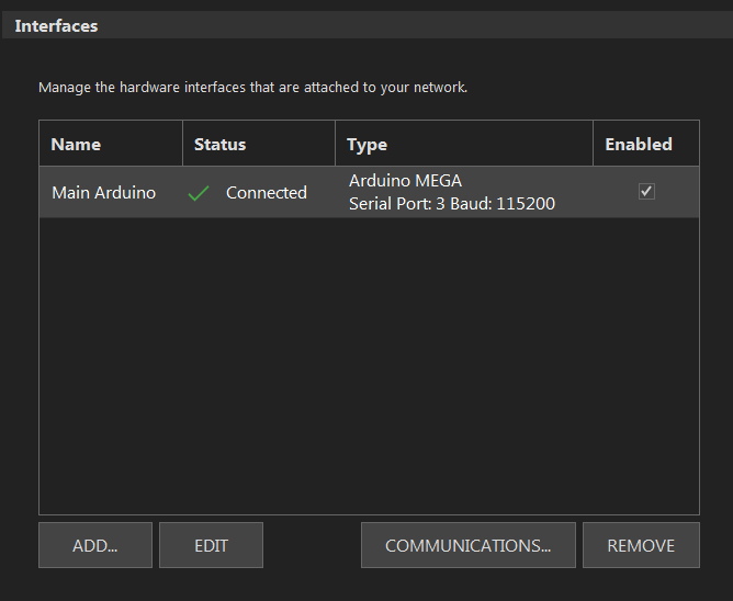
Yes you'd need to use Arudino instead of Raspberry Pi. (can be any ESP32 if you have smaller setup, Mega is most versatile), for uploading arudino firmware PC is needed. But that step is not so complex nor frequent -> you just need to follow instructions provided.
However, you need a small PC where you will run BruControl software which is currently running AFIK only on Windows.
You could run Windows on Raspberry Pi4 but it's a harder way (IMHO).

If my assumption is correct, could I skip the requirement of the laptop at the brewing area with this Arduino ? Or I suppose if I didn't care to do this I could remote desktop into the laptop?
You don't need PC while brewing, you can use a tablet, but you then you must use Arduino MEGA or ESP32 with (Ethernet) WiFi shield (like me).
I am using Tablet during brewing which is connecting using RDP to PC/Windows running BruControl. Web interface is announced but not yet available, for me a killer feature :) .
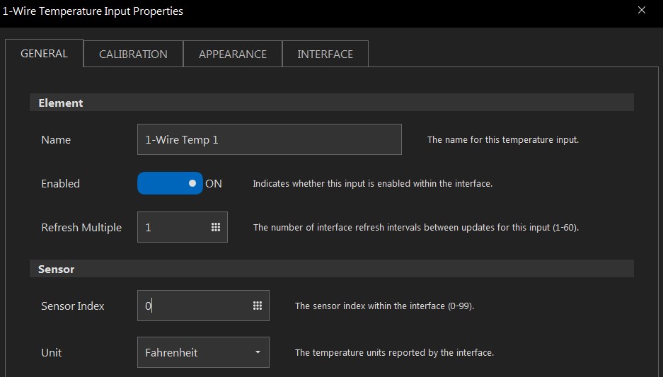
From what I gather the Arduino has some analog inputs as well, so if I went this way, if I decide to do stuff like pressure sensing/flow sensing I wouldn't have to invest in ADC boards like I would the raspi?
I have analog sensors and I dont use additinal ADCs, but some passive elements need to be added. Please check more schematics here: Schematics – BruControl. It's nothing complex. And you don't need raspi anymore.

Also does Brucontrol have any type of control over 2 sensors with 1 element simultaneously? I think it's been called cascade PID. Essentially if I want to ramp my mash up, is there anyway to set my rims tube (with sensor) up to go full power or preferable a certain amount of power, and base when it turns off on the mash tun sensor gets to set point, then switch over to the RIMS tube for temp control?

I am using 2 step approach without cascade PID.
First I power up my RIMS with Duty Cycle to full power (ramp up) until certain temperature (-2C from the target) then I switch to PID heating
That means yes you can do that. with DC or PID you can use same sensor (RIMS sensor)

Just a side comment BruControl is very powerful taking into account Arduino possibilities and scripting language, and its worth investing in a small PC for running the control software.
Check some of my posts I recently posted demo video, maybe it helps to understand what can be done with BC.

Cheers and sorry for several edits, I accidentally published unfinished post :)
 
Last edited:
Thanks for all the information! I have a laptop I don't use much that I'll keep near the system.

I bought a screw terminal shield. From what I gather it should be as simple as transferring over the wires from the raspi hat into the correct GPIOs on the Arduino shield. Thank you for the schematics link too, now I know where to put the 1 wire.

No problem, glad I could be of little help.

Please check also interface wiring maps, they are important for mapping:

https://brucontrol.com/build/interface-wiring-maps/https://brucontrol.com/wp-content/u...Wiring-Map-Arduino-MEGA-2560-v1.1-FW-v45E.pdf

Schematics are examples, many of the pins used can be changed as per wiring map.
 
@BrunDog so with the use of the double pole contactors, are you suggesting to use the SSR to switch the coil? If so, can the coil handle the high switching frequency it would see through an SSR for a pwm heating element?
No! The Contactor is like a Safety Switch. It provides power to the Proportional Controller on one Hot Leg and To the Element of the Other Hot Leg. The Proportional Controller controls the Temp and is what cycles.

The only reason for the Contactor is there is NO hot leg on the HLT Element looking for a good Ground (YOU) when the Element is not called for.

Logic:
//Turn HLT Element On
//First Turn on Contactor Digital Out
"HLT Element Contractor" state = true
//Turn on the Proportional Controller
"HLT Element" state = true


In my old BCS I used a contactor with Hysteresis and a two degree (F) swing. I have a need for more precise control.
 
Once again, a request (repeat).

I was playing with the screen again and the visual automated pump. If I have unlimited backgrounds , I could display moving wort on my screen and have valves open and close. It would be nice if the Workspace also had these unlimited backgrounds. If there was a script command to change the path of Background 1, It would solve a lot of issues that I am having with the "perfect" screen.

All it would take is one script command to change the "path" of the existing field of background 1 of an Element.

Something like a new attribute named backpath:

MyElement backpath = "C:\Brucontrol\Media\TransferWort.png"

The Workspace Background does not currently have any way to change the background, but a backpath attribute would work there as well.

Of course, the wav file path would also be nice: an attribute like wavpath for fileindex 1 where I could change the path for the wav file.

I was sampling on google sides and it worked good there as I could simulate moving wort. Just having a limited 3 backgrounds is not enough for what I am trying to do.
 
New to brucontrol and trying to add some 1-wire DS18B20 temp sensors and 9-24V reverse polarity ball valves. So far I have the temp sensors wired, red: 5v, black: gnd, yellow: digital pin 2 on a arduino mega 2560. However, I do not see 1-wire as an option when adding a new device like is shown in the brucontrol manual.

In addition, I seem to be having an issue where the Mega will disconnect from brucontrol every couple minutes for about 5 seconds then reconnect.

I am using a windows 7 lenovo laptop and connecting the mega over USB.

Thanks for the help.
You need to look at the wiring map for the version of firmware installed. This is a link for 45e
https://brucontrol.com/wp-content/u...Wiring-Map-Arduino-MEGA-2560-v1.1-FW-v45E.pdf


You need to read the note at the bottom. Your one wire are virtual ports 200 to 209


O = 1-Wire Input (Note: all 1-wire data pins must be tied to only one interface pin. All sensors are addressed by virtual ports 200 - 209 in BruControl).

Make sure you also wire the one wire correctly:

Look at this schematic:

https://brucontrol.com/wp-content/uploads/2017/03/BruControl-1-Wire-Schematic.pdf


I personally would use Pin #5 for One Wire. Pin 2 is one of the few ports you can use a flow meter on. You may not use one now, but in the future????
 
Thanks for this information. So on the hardware side I should run all the data pins in parallel back to a singular arduino pin, potentially #5? How will I be able to separate out the data for 10 different temperature points?

and the 5V power needs to have a 4.7k pull down resistor?

Any advice on reverse polarity ball valves?

Hi,

We could definitely use more information to give some informed advice. Otherwise we are guessing. Schematics, pictures, details of what you have (models, etc.). I know it takes more time to document these things, but we are certain to be able to help sooner.

Taking some stabs: 1-wire sensors are on virtual ports, per @oakbarn 's comment. Wire them all to one input pin, such as #5. They are all read separately via sensor indexes. Check out the manual for specifics. 1-wire sensors can be prone to noise. A good power supply it important. Also, if you have lots of sensors, it is important to keep them as short as possible. Otherwise, shielded wire is recommended. Dropping the pullup resistor from 4.7k to 2.2k can help (wire two 4.7's in parallel if its all you have).

I'm not sure what you mean by "reverse polarity valves". More details needed here.

Regarding disconnects, are they happening on their own, or when you activate some things? These can be tricky to diagnose, but power supply is usually the starting point. Isolating devices until you find the problem one(s) is the best way to determine the source.
 
Hi all,

Just posted BruControl build 1.1.0.19. We need to finish a few final updates and we'll call it 1.2.

This version fixes the Data Explorer failing to re-open after closing. It fixes an issue with PID & Dead Band being unable to use PWM for a device when PWM is an existing element on the same interface & port (note: this is important for UniFlex users with proportional SSRs). Also adds a switch to enable/disable secondary value displays for devices which have them (e.g. PIDs).

BTW, for anyone on the fence, we think this is tested well enough to use in production. Please make sure to read the associated product note for upgrading.
 
Hi,

We could definitely use more information to give some informed advice. Otherwise we are guessing. Schematics, pictures, details of what you have (models, etc.). I know it takes more time to document these things, but we are certain to be able to help sooner.

Taking some stabs: 1-wire sensors are on virtual ports, per @oakbarn 's comment. Wire them all to one input pin, such as #5. They are all read separately via sensor indexes. Check out the manual for specifics. 1-wire sensors can be prone to noise. A good power supply it important. Also, if you have lots of sensors, it is important to keep them as short as possible. Otherwise, shielded wire is recommended. Dropping the pullup resistor from 4.7k to 2.2k can help (wire two 4.7's in parallel if its all you have).

I'm not sure what you mean by "reverse polarity valves". More details needed here.

Regarding disconnects, are they happening on their own, or when you activate some things? These can be tricky to diagnose, but power supply is usually the starting point. Isolating devices until you find the problem one(s) is the best way to determine the source.

Attached are screenshots of how my brucontrol is configured along with my 1 wire config (using the virtual ports allowed me to add the sensor, thanks @oakbarn ). However I am unable to get any data readings and am not able to get any from the test onboard led on MEGA (I have it configured to pin 13/port 13 ).

Here is a link of the valves I am using and I also attached the provided wiring diagram for them. I will be using these to automate water coming into the tanks as well as moving liquid between the tanks.

Disconnects happen on their own pretty regularly, about every 60-120 seconds or so. Currently I'm not using my PSU just the MEGA powered over USB and trying to get a sensor reading as an initial test.
 

Attachments

  • Screenshot 2021-03-23 000805.jpg
    Screenshot 2021-03-23 000805.jpg
    58 KB · Views: 24
  • 2.PNG
    2.PNG
    11.4 KB · Views: 26
  • 513JG9LR77L._AC_.jpg
    513JG9LR77L._AC_.jpg
    36.8 KB · Views: 27
  • Capture.PNG
    Capture.PNG
    4.4 KB · Views: 27
  • 4.PNG
    4.PNG
    10.5 KB · Views: 18
  • 6.PNG
    6.PNG
    28.1 KB · Views: 16
  • 7.PNG
    7.PNG
    10 KB · Views: 15
Last edited:
Attached are screenshots of how my brucontrol is configured along with my 1 wire config (using the virtual ports allowed me to add the sensor, thanks @oakbarn ). However I am unable to get any data readings and am not able to get any from the test onboard led on MEGA (I have it configured to pin 13/port 13 ).

Here is a link of the valves I am using and I also attached the provided wiring diagram for them. I will be using these to automate water coming into the tanks as well as moving liquid between the tanks.

Disconnects happen on their own pretty regularly, about every 60-120 seconds or so. Currently I'm not using my PSU just the MEGA powered over USB and trying to get a sensor reading as an initial test.

How many sensors... how are they wired? How long? Are you using a 4.7k resistor? Are you resetting the MEGA or at least the 1-wire bus after making wiring changes (see %3 control code). You should test with just ONE sensor first, then add them.

Disconnects with USB are rare. Is this happening with NOTHING else attached? What do you mean not able to get any from the test onboard LED? You should be able to turn it on and off as a Digital Output on port 13. What versions of the application and firmware are you using? I suggest application 1.1.0.19 and firmware 45O (serial version).

You can email us the logs and we can take a look as well.

10 DS18B20 sensors, but only testing 1 for right now. Wired over XLR. I am currently not using a resistor. I have not reset the 1 wire bus using control codes, but now see how to do that in manual. The only resetting I was doing with the physical reset button on the MEGA, not sure if that's what you're referring to as a MEGA reset.

Disconnects are happening with nothing attached and I am not able to turn on and off the onboard LED using port 13, as shown in screenshots on my previous post. I am using BruControl 1.1.0.17 and firmware 45H.S
 
1 wire uses open drain to avoid bus contention. It wont work without the pull-up resistor.
I'll be sure to add one. As for the serial disconnects and being unable to control the onboard LED, here is my communications log.

Edit: I did change the firmware to 45O (serial version), as @BrunDog suggested.
 

Attachments

  • b1dEwA.png
    b1dEwA.png
    142.2 KB · Views: 13
Hi, all.
I started to build my setup, as i never had experience in any automation its really slow proces for me.
I have question for help with the scripts as its for me rather new thing.
Iam planning to automate pasteurization and its really simple setup in hardware but dont know how to script this.
Iam using steam valve histeresis ,one temp 1-wire sensor in bottle, one 1-wire temp sensor in tun, and two butterfly valves (valve 1 and valve 2) to sprinkle cold water after process is done.Iam doing it manually so far with the exccel sheet attached. Could someone help me with that please?
Regards
 

Attachments

  • Pasterurization of beer.zip
    2.1 KB · Views: 17
I'll be sure to add one. As for the serial disconnects and being unable to control the onboard LED, here is my communications log.

Edit: I did change the firmware to 45O (serial version), as @BrunDog suggested.

Despite the log saying it's connected, it is not really connected. It sees the COM port, but until you see an Rx response, you aren't actually receiving a positive connection. Something seems wrong with the USB port. This is why your digital output on port 13 isn't working - because it is not actually getting communicated.

Possibly drivers? Do you have the COM port set correctly? Baud speed, etc. Is the port open? Make sure nothing else is trying to communicate with it. Debug this with NOTHING connected to any pins.

It was the arduino drivers incorrectly installed. Now it shows the MEGA on COM port 4 and the connection is stable (no more disconnects.) thanks.

However, I am still unable to control the LED or getting a reading from the 1 wire even with the resistor I added. I've tried rebooting the arduino and using the 1 wire %3 command. Attached is a picture of my workspace with the 2 devices getting no reading.
 

Attachments

  • Capture.PNG
    Capture.PNG
    3.2 KB · Views: 14
Hi, all.
I started to build my setup, as i never had experience in any automation its really slow proces for me.
I have question for help with the scripts as its for me rather new thing.
Iam planning to automate pasteurization and its really simple setup in hardware but dont know how to script this.
Iam using steam valve histeresis ,one temp 1-wire sensor in bottle, one 1-wire temp sensor in tun, and two butterfly valves (valve 1 and valve 2) to sprinkle cold water after process is done.Iam doing it manually so far with the exccel sheet attached. Could someone help me with that please?
Regards

I'm sorry - I am not understanding what you are trying to do. I don't have any experience with pasteurization. Do you have any drawings showing the hardware, process flow, devices, etc?
 
Hi,
My process is like this:
- i put bottles to a mash tun, and open steam valve from steam generator to reach a temperature 62 degrees C inside a bottle
-as in .xls attached i note every step temp/time in the spreadsheet
-when i get around 20 pasteurization units i open a valve with cold water to cool down a bottle as fast as possible.
thats is it.
Problem is that i have to put numbers in spreadsheet as temp rises by hand , would be awesome for me if i put how much PU i want and process is fully automated.
This stage is most troublesome for me , in my rig i have 12 butterfly valves , 10 1-wire probes , vf controlled pump, 2 flow sensors, 2 pressure volume sensors, one wood pellet burner for boiling (pwm) , and steam generator for mush tun, beer pasteurization and keg washing. Software is awesome , and i think its the only one can do so many fancy stuff that you can only think.
Board im using is arduino mega, with 16 relay board and bunch of converters like pwm to voltage , voltage to curent and L298N bridges to drive 2-wire actuators etc.
The spreadsheet explanation:
Pasteurization starts from 45 C and in this temp i start to note numbers.
I measure a time of actual temp is lasting like 45- 1 to 3minute, 46-3 to 6 minutes, 47- 6 to 8 minutes and up to 62. Spreadsheet is calculating units for every temp/time and adding it together, when i reach 62 C summary is like 20 PU and i start to cooling down, temp is decreasing but pasteurization is still happening
, spreadsheet is calculating till 45 C .
 
Last edited:
If you are lost in the weeds when it comes to how to write a script to automate your process, I would recommend starting with a flow chart or state machine diagram that maps out the entire process for each step. Include what is happening at each step, what causes the process to move to the next step, and what changes between steps. From there you can tackle scripting each step individually, and eventually tying them together. Divide and conquer.
 
Hi,
My process is like this: .....

-as i calculating till 45 C .
As @crane said, divide into steps. If you look as some ones script (or your own later), it can look complicated, but it is simply a series of steps and logic.

For example, you have a spread sheet with your steps. Just figure out what you do NOW without BruControl and write down each step in detail. You own list may not really contain all the steps you manually do to do something. As an example, you may have a step to fill your mash tun with water as one step, but even your manual method may contain many sub steps. You need those small steps.

For example, when you fill your Mash Tun, you may first
1. Check that all your valves are closed.
2. Turn on Water Hose.
3. Wait until water reaches mark in Mash Tun.
4. Turn off Water Hose.
 
Ok, i will try to start from begining, because i overthought it little a bit . Its jut simple math of time/temp.
 
Here is an example. Needs refinement, including the incorporation of Time into the PU calculation (your spreadsheet shows it in the formula but it is not in the cell calculations so I'm not clear).

[initialization] new value PU new value EXP "SteamValve" enabled = true "WaterValve" enabled = true [loop] "SteamValve" state = ON wait "Temp" value > 45 [pasteurization_check] EXP = "Temp" value PU = 1.393 ^ EXP sleep 1000 if PU < 20 goto "pasteurization_check" endif "SteamValve" state = OFF sleep 3000 "WaterValve" state = ON wait "Temp" value < 45 "WaterValve" state = OFF sleep 5000 goto "loop"
 
Thank you Sir, i will look into that. The spreadsheet works calculating a value for every minute , i put temp value for every cell from first minute to last minute of pasteurization.
1-46-PU
2-46-PU
3-47-PU
4-48 PU etc
And its toping it up at summary cell for PU of whole process (15,78 PU ) like in example pdf.
Regards
 

Attachments

  • Pasterurization of beer.pdf
    11.5 KB · Views: 12
Feature request: A tool that duplicates the appearance of one element and applies it to the other. One step further would be to allow the user to select which properties are copied when using the tool- size, text size/location, etc..
 
Also request an individual lock on an Element size and position. I still have them changing size and location when I open the script Window. It is an intermittent issue.
 
The next build will increase the amount of pixels an element must be dragged before it becomes “loose”.

That said, the elements should not be moving with the script window opening and closing. Please send a screen video if you can replicate it.
 
I will try to replicate and get some screen shots but it is intermittent. There may be something I am doing to cause it, but I am not sure. In addition, I am trying to get a "flow" of my water and wort to be displayed using graphics that change using a global Element as a back ground. Since I only have 3 choices as to backgrounds of an element, it will require several Globals. The issue that I have as I also have some Digital Outs (my Pumps) that have a transparent background until I put the Global on the screen the last Z Order (or at least after the Digital Outs) on the screen. The LED Digital Outs are no longer Transparent but have a Black Background so it will not work. If I could select a Path for the Workspace background image (where the Digital LEDs are transpanemt), it would solve my issue as I could get my flow with changing only the background image. I would change it for every time the flow changed.

1. Transfer Strike,
2. Vorluft
3. Mash ( do recycle the Wort)
4. Flush Manifold from RIMs (or HEREMS)
5. Transfer 1st Run
6. Add Sparge
7. Transfer Second Run
8. Clean MLT
9. Sanitize Manifold
10. Whirlpool
11. Rest
12. Transfer to Fermentor

and there may be more as I do 2 batches in different vessels some days.


If could change the Path for Image 1 of an Element, I could delete several stacked Elements that I have that are hard to manage. I would also like to be able to change the Path for File 1 of a wav file for an Element. If it was easier to program, maybe 20 choices would work for the Image and wav file.

As an aside, my new Barn is up and I am waiting on stainless and Pumps. I get something almost every day. Couple of months before my first brew in my Phoenix brewery.
 
Last edited:
I did some more trying to find the issue with resizing of elements and it is the Global Elements are the culprits. It seems associated with the Script Pane being open and using the scroll bar on the Workspace to see under the Script Pane. If I have a large Global that basically takes up the screen, I can repeat the issue. I had issues with other Elements types before, but those are apparently fixed now.

I can repeat it when I close then reopen the program.

I have other Globals that are not full screen and I have had those resize as well and I think it does have something to do with the Scroll Bars, but I cannot repeat that yet.
 
Last edited:
So I've had enough of wrestling with a rPi to run Brewpi or Fermentrack. Those programs seem to work well, but Linux is not my jam. With a Windows PC and Brucontrol, is it as simple as unplugging the rPi and plugging into the Brucontrol? The Brucontrol website videos make me think it could be that easy. Current setup (see pic) is the standard issue Brewpi remix/Fermentrack.
 

Attachments

  • 16174975170868285104432675101741.jpg
    16174975170868285104432675101741.jpg
    1.5 MB · Views: 37
It could be that easy... kinda. Only real issue is we don't support the UNO any longer because it has limited memory capacity.

You could replace the UNO for a MEGA. Would basically be a dead swap (note the MEGA is a bit bigger). A clone is fine... would cost you about $12-15 from an online retailer. An evaluation of the BruControl software could tell you what you need to know.

We're here to help you with any questions or concerns along the way!
 
Back
Top