BruControl: Brewery control & automation software

Homebrew Talk - Beer, Wine, Mead, & Cider Brewing Discussion Forum

Help Support Homebrew Talk - Beer, Wine, Mead, & Cider Brewing Discussion Forum:

This site may earn a commission from merchant affiliate links, including eBay, Amazon, and others.
6 months?!? Wow... Covid backlog?

I would personally never brew without bottom drains. Moronic that anyone has to move their kettle to clean it IMO... don't care how small it is.
I bought one of the very first 35 Gal Mash Tuns from Stout. Basically everything was made to order then and it took a long time.

As for bottom Drains, I would get them on any new Mash Tun. I built some stands that tipped so it was easy to clean my 45 g and 30 g Brew Kettles in place. The same with our 35g Mash Tun. They were built in a way so the tip over was limited with a Chain on the handles and another chain from the base to a wall. Being able to tip over a MLT full of wet grain was worth it weight in gold.

I could drain them 100% in place (without a bottom drain) and it was also easy to rinse while tipped. My Brew Buddy Dave cleaning the MLT.
IMG_1680.JPG
 
The reason for a bottom drain on the MLT is to be able to get ALL the Wort. Tipped over it was very easy to clean. I always had Wort left without a bottom drain. We have to remove the hose from the pump and tip the MLT a little to get the 2 gal of wort in the bottom which was a PITA. We always spilled Wort on the floor. I actually got the idea of a tippy stand from some vendor. More Beer? I made it for the MLT To get the grain out. It made cleaning so easy we made them for our other vessels. Brundog is correct. Cleaning in place is 1000% better.
 
For those interested in iSpindel... took a look and think the best path is to have it post data to BruControl via Data Exchange. It looks like it might work out of the box, but if not. I got the firmware installed on both a Wemos D1 and a Node MCU, but both are giving me the same results where it is not establishing the access point to enter the WiFi credentials. The debug reports "reboot RFCAL" which I think is related to deep sleep, but I don't understand why it would enter sleep when it is supposed to leave the access point open.

I'm (maybe stupidly) thinking its because there is now other hardware connected and I am powering via USB. I guess we need to get one of these, but don't have the time to build one. Anyone know where to buy one?
 
Is there a reference or tutorial out there to help understand what the device log is reporting?
 
For those interested in iSpindel... took a look and think the best path is to have it post data to BruControl via Data Exchange. It looks like it might work out of the box, but if not. I got the firmware installed on both a Wemos D1 and a Node MCU, but both are giving me the same results where it is not establishing the access point to enter the WiFi credentials. The debug reports "reboot RFCAL" which I think is related to deep sleep, but I don't understand why it would enter sleep when it is supposed to leave the access point open.

I'm (maybe stupidly) thinking its because there is now other hardware connected and I am powering via USB. I guess we need to get one of these, but don't have the time to build one. Anyone know where to buy one?

I am pretty sure it's because it's connected and powered it only over USB. AFI can remebrer it goes to deep sleep when battery voltage is lower than specific value. So somewhere it failing to measure it ...

I asked FB group for the seller in the US.
If I don't get good answer until Monday...I could also send you one from Switzerland ? You would only need to install battery. Would that work for you? If yes just need an address.

Until it arrives, if your endpoint is available over internet I can set one of my own to send you data.

EDIT: darn... I just realized I am not at home until Friday...
 
Last edited:
For those interested in iSpindel... took a look and think the best path is to have it post data to BruControl via Data Exchange. It looks like it might work out of the box, but if not. I got the firmware installed on both a Wemos D1 and a Node MCU, but both are giving me the same results where it is not establishing the access point to enter the WiFi credentials. The debug reports "reboot RFCAL" which I think is related to deep sleep, but I don't understand why it would enter sleep when it is supposed to leave the access point open.

I'm (maybe stupidly) thinking its because there is now other hardware connected and I am powering via USB. I guess we need to get one of these, but don't have the time to build one. Anyone know where to buy one?

It needs to be connected with the sensors I have struggled with the same issue.
 
I am pretty sure it's because it's connected and powered it only over USB. AFI can remebrer it goes to deep sleep when battery voltage is lower than specific value. So somewhere it failing to measure it ...

I asked FB group for the seller in the US.
If I don't get good answer until Monday...I could also send you one from Switzerland ? You would only need to install battery. Would that work for you? If yes just need an address.

Until it arrives, if your endpoint is available over internet I can set one of my own to send you data.

EDIT: darn... I just realized I am not at home until Friday...
Only way to get it in the USA is via ebay.
@BrunDog I can send it in a week if you don't get it by then. Pls let me know.
 
I see a couple of eBay vendors but mostly UK shippers. I’ll look some more.

Has anyone tried the generic http post yet? If it can’t work, then I think a simple code mod then a pull request can get it to post data to BC as a permanent solution.
 
I see a couple of eBay vendors but mostly UK shippers. I’ll look some more.

Has anyone tried the generic http post yet? If it can’t work, then I think a simple code mod then a pull request can get it to post data to BC as a permanent solution.
I was using it first only with generic http post. It was working.How can I help?

I just send you a PM with a link to ebay iSpindel auction (still uk) but seller would send it to US. HTH
 
I was using it first only with generic http post. It was working.How can I help?

I just send you a PM with a link to ebay iSpindel auction (still uk) but seller would send it to US. HTH

Great, thanks! I will buy it.

When you say "working"... do you mean sending data to BC? I would assume not, otherwise people wouldn't be asking.
 
Great, thanks! I will buy it.

When you say "working"... do you mean sending data to BC? I would assume not, otherwise people wouldn't be asking.

My bad. Now I see I wrote something stupid. I meat I used generic http to send data to another server . Sorry.
 
Hopefully an easy question for the folks in this thread: I have BC setup with a Mega connected via USB. I set it up back in the 1.0 days with firmware v43. I'd like to update the firmware to v45, and I just want to make sure that there aren't any gotchas of which I should be aware (it's not going to break my RTD sensors or change any numbering or anything crazy like that, right?). Is it as simple as running the InterfaceSetup batch file and letting it do its thing? Sorry if this question has been answered a couplea dozen times previously.

Thanks.
 
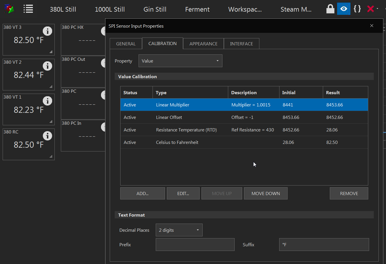
RTD Update...I received the 0.01% 100ohm and 0.1% 10 and 20 ohm resistors and made up three plugs and spent several hours testing and found a procedure to have a RTD amp calibrated in about a minute...

Set up RTD SPI device in BC with multiplier, offset, RTD, and CtoF calibrations in that order (trust me on this, this is where half the time went)
put the higher ohm test plug in and adjust the multiplier to read the theoretical temp for that test plug (~124.8F for 120ohms)
put in the 100ohm test plug and make the linear offset take it to 32.0F
go back to 1st test plug, it should be close, adjust if needed
go back to 100 ohm, it should be on, I did not experience it being off at this point, but it is possible.
plug in the middle test plug(110ohm in my case) check if it is linear... (all of mine were very close)

Here is what I got with my 4 PT100 probes in a jar after the above calibration:
(I can re visit the probe that is a couple tenths off, this is the RP-3 assembly that had the raw readings way off in previous post, I am really happy)
I will do a write up next week...

1602516587774.png
 
Glad you are happy!

You can always use a lookup table too for values you really want to dial-in... our RTD calibration uses the polynomial for Pt... might not always be right for non-Pt probes.

Also... we should try to avoid connectors for RTDs altogether if possible as they will have some resistance variance.
 
RTD Update...I received the 0.01% 100ohm and 0.1% 10 and 20 ohm resistors and made up three plugs and spent several hours testing and found a procedure to have a RTD amp calibrated in about a minute...

Set up RTD SPI device in BC with multiplier, offset, RTD, and CtoF calibrations in that order (trust me on this, this is where half the time went)
put the higher ohm test plug in and adjust the multiplier to read the theoretical temp for that test plug (~124.8F for 120ohms)
put in the 100ohm test plug and make the linear offset take it to 32.0F
go back to 1st test plug, it should be close, adjust if needed
go back to 100 ohm, it should be on, I did not experience it being off at this point, but it is possible.
plug in the middle test plug(110ohm in my case) check if it is linear... (all of mine were very close)

Here is what I got with my 4 PT100 probes in a jar after the above calibration:
(I can re visit the probe that is a couple tenths off, this is the RP-3 assembly that had the raw readings way off in previous post, I am really happy)
I will do a write up next week...

View attachment 702199
why the -1 offset?
 
why the -1 offset?

B.... as in Y=MX+B (M is the multiplier and B is the offset, both were required to fit the line to the slope shown by two resistance values... )


Like Brundog says, polynomial would be better, but Pt (and Cu phaux-Pt) probes are both pretty flat.. I may do the polynomial someday... Right now I need quick and easy, and I need the connections until I get it the way I like it, then I can solder right to the RTD amp board if I want to...
 
I just pulled the trigger on a couple of TILT hydrometers, what is the current best control board to make them talk to BruControl?
 
Thanks, I will pick one of those up today.
There is a nice one with lots of bells and whistles at BruControl!

Model UU-1-EX: ESP32 UniShield, with interface

Regardless of where you get one, I would get one with an external antenna. Before my disaster, I had one in a jacketed fermentor inside a foil lined room with a Tilt repeater next to the fermentor. MY ESP 32 was about 30 feet away from the room and I had a good connection. If you have good Wifi in the Fermentor room, you do not need a repeater but the closer to the fermentor, the better.
 
@BrunDog, can you please clarify something from one of the Unicon videos?

Where did you get these neat little terminal blocks, and is the plan to wire each I/O directly to them as needed?

Thank you!
 

Attachments

  • terminalblock.png
    terminalblock.png
    508.8 KB · Views: 39
I must say that the IFM SM6004 sensor, while having a few limitations, provides very accurate flow measurement.

SM6004 - Magnetic-inductive flow meter - ifm electronic

Yes it is limited to 80 C and 6.6 gpm but the temp limit is only limiting the bonus temp output as it is really a flow meter and the 6.6 gpm is not a value I even remotely approach so it is not technically a limit.

Hi VacationLand, any update on your experiences with the IFM SM6004 flow meters? I'd like to use 2-3 for controlling proportional valves, but also for computing volumes for HLT-MLT and MLT-BK transfers, to back up/compare to hydrostatic pressure sensor readings. Have you been able to successfully script an accurate totalizer within BruControl by using the gpm (or l/min) data?
 
I've narrowed my disconnect issue to one of twelve pt100 amplifiers.

Anyone know of a test or series of tests to check pt100 amplifier specifically adafruit max31865?

I don't get an immediate disconnect so trying to avoid the plug in and wait method for each.
 
How do you know it is one of 12? If you know that, I would think you would know which one it is.
Everything is stable with all of them disconnected. Also have all thermometers and CS 1-4 wires disconnected. When I install all twelve I have issues. Let me rephrase it may be 1, 12 or anything in-between. Do you know any way to test with multimeter?
 
Last edited:
If CS 1-4 are disconnected, they cannot work. Are you saying that 11 work, but the 12th causes it to fail?

I'm 99% confident, as I have been since the beginning, you have a noise or wiring problem or combination, and that can only be "seen" by a scope, not a meter.
 
If CS 1-4 are disconnected, they cannot work. Are you saying that 11 work, but the 12th causes it to fail?

I'm 99% confident, as I have been since the beginning, you have a noise or wiring problem or combination, and that can only be "seen" by a scope, not a meter.
What I'm asking is if one can test a max 31865 with a meter.
 
Last edited:
You can test the voltage input... but if it’s noisy or erratic, you will not see it with a VOM, only a scope.

You can test for ground loops. Check the voltage differentials across ground points.

You cannot test the SPI (serial) communications - a scope is needed.

On the probe side, you cannot test it but replacing the RTD with a resistor should give you a corresponding result (eg 100 ohm = 25 degs C when the calibration is on in BC).
 
I had an issue with one MAX 31865. The only way I found it was to remove all the MAX31865 from the RP-3 and add them back one at a time and test. When I added the bad one, it was very apparent.
 
Hi VacationLand, any update on your experiences with the IFM SM6004 flow meters? I'd like to use 2-3 for controlling proportional valves, but also for computing volumes for HLT-MLT and MLT-BK transfers, to back up/compare to hydrostatic pressure sensor readings. Have you been able to successfully script an accurate totalizer within BruControl by using the gpm (or l/min) data?

So far the flow meters have been reliable and accurate for both flow and temperature but I've been sidetracked by a home renovation project the last six months and not much has progressed recently. The last time I was working on my brew rig I was able to use two IFM flow meters as the input for two pump PID control loops used to establish a constant recirculation rate between two vessels. Along side of this, I am using a scale for each vessel to maintain a constant volume in each while performing a recirculation infusion mash (RIMS). The scales are used to to monitor vessel mass and prevent draining one tank too far (below the heating element) and over filling the other if flow rates were to get out of sync due to a stuck mash. I have not scripted the IFM SM6004 flow meters as a flow totalizer but rather choose to install the inexpensive hall effect flow totalizers instead for simplicity (via the BC counter inputs). The IFM flow meter unit of measure on the display and at the 4-20 mA analog output is configurable for flow (gpm or lpm) and temperature (C or F).
 
I have a few of the IFM SM6004s in my setup. I use one for controlling the flow rate of my HLT pump and one for controlling the ground water flow rate through my counter flow chiller. Both work very well for that. I have another that I use with a script to add up the total volume going into the fermenter at knock out.

I started out with the hall effect sensors and swapped most of them out for the SM6004s. I had written a few scripts for calibrating the flow sensors by measuring the change in volume over time for both sending and receiving vessel to calculate the flow rate and compare to the sensors output. This was crucial for calibrating the hall effect sensors, but when I ran those scripts against the SM6004s they were very accurate without any additional calibration needed.
 
I have another that I use with a script to add up the total volume going into the fermenter at knock out.

I started out with the hall effect sensors and swapped most of them out for the SM6004s. I had written a few scripts for calibrating the flow sensors by measuring the change in volume over time for both sending and receiving vessel to calculate the flow rate and compare to the sensors output. This was crucial for calibrating the hall effect sensors, but when I ran those scripts against the SM6004s they were very accurate without any additional calibration needed.

Thanks for your replies crane & VacationLand; this confirms that these flow/temp. sensors offer an exceptional price/performance ratio, as on eBay they can be had for $32/ea (used, shipped: FLOW METER SENSOR IFM EFECTOR | eBay), along with some BSP-TC adapters (e.g., Brewers Hardware 1"/1.5" Tri Clover Compatible X 1/2" Female BSPP) and M12 cables (e.g, https://www.amazon.com/gp/product/B...&pf_rd_p=edaba0ee-c2fe-4124-9f5d-b31d6b1bfbee), totaling of <$80/sensor. I guess additionally one needs a 250ohm (or maybe 233ohm) resistor for each sensor as well, to connect to the interface.
 
I'd suggest you get versions that output pulse signals. Easier and more accurate IMO than analog.

That said, one caution that relegated me to hall effect FM on my personal rig... pulse resolution during sparging (low flow). I fly sparge and measure the flow rate to ensure a roughly 1 qpm (~1 lpm). At that rate, the hall effect sensor outputs roughly 6 pps. So that's not a lot of resolution. Fortunately, sparging is very forgiving, but a FM which outputs much less pulses per unit volume will negatively affect resolution at this low a flow rate, so the IFM's were a show-stopper for me. If you don't do this, then no worries!
 
Thanks for your replies crane & VacationLand; this confirms that these flow/temp. sensors offer an exceptional price/performance ratio, as on eBay they can be had for $32/ea (used, shipped: FLOW METER SENSOR IFM EFECTOR | eBay), along with some BSP-TC adapters (e.g., Brewers Hardware 1"/1.5" Tri Clover Compatible X 1/2" Female BSPP) and M12 cables (e.g, https://www.amazon.com/gp/product/B...&pf_rd_p=edaba0ee-c2fe-4124-9f5d-b31d6b1bfbee), totaling of <$80/sensor. I guess additionally one needs a 250ohm (or maybe 233ohm) resistor for each sensor as well, to connect to the interface.
I have several of these as well. If going to tri-clamp, these work great and thread right on/off as needed. Also keep in mind that they need to be a bit of a distance away from flow disturbance like the pump or a valve (I think its 6x pipe diameter) otherwise they can give faulty readings. As for flow totalizing, just make sure your math variables in your scripts have appropriate precision and they will prove to be exceptionally accurate.
PXL_20201019_203707260.jpg PXL_20201019_203750077.jpg
 
Last edited:
While I would very much rather use a more modern bus to bring in sensor information (say Profibus or Ethernet/IP), the current state of Arduino/BC does not reasonably allow for that. Analog I/O is reliable and proven in the industrial automation world. That said, for flow totalizing, I would go with a device that outputs a pulse just to keep the scripting out of the totalizer aspect. I want my totalizer to function when I'm doing manual work sans script but that is just a personal preference. For flow velocity inputs...it's my preference to not count pulses for that.

I too would say they represent a solid value given the accuracy, the compact size of the unit, the cost, and the fact that it has a field display. I have found the field display to be quite handy to quickly keep tabs on things while hovering over the kettle. Of course, it is an induction based meter so it wouldn't read anything with the output of a RO/DI water system but that isn't likely a problem for the home brewer.
 
Back
Top