BruControl: Brewery control & automation software

Homebrew Talk - Beer, Wine, Mead, & Cider Brewing Discussion Forum

Help Support Homebrew Talk - Beer, Wine, Mead, & Cider Brewing Discussion Forum:

This site may earn a commission from merchant affiliate links, including eBay, Amazon, and others.
I think you could use Ethernet jacks and wiring for sensors, but you would be missing out on the benefit of shielding.

I do networking in my day job and I am pretty sure Cat5e and Cat6 are shielded and twisted pair inside so that should cut down the chance of picking up noise don't you think?
 
I am thinking of this myself, but I am not sure how to add DIN rails to the box.


I was going to try this (although, I am nowhere near this step). I am going to do research on the wiring first to make sure there wont be any loss.

I think the general DIN rail adapter will be easy to find once I have a footprint for the PC, I looked at the System Requirements in the BruControl manual and it looks like either the NUC or zbox can be configured to meet those, I'm more concerned on how the RFI/EMF they produce inside the control panel would effect the Arduino MEGA.

The UniCon uses 8 pin I/O's so Ethernet just seems like a logical way to terminate at the control panel but since this is my first time building a BruControl panel, I don't want to assume I am on the right track!
 
If you are more comfortable crimping vs soldering and are ok with the increased costs, I think the shielded patch panel will work fine. Keep in mind that the UniCon has 8 IO, but there are typically more than 8 wires associated with those 8 IO points. For example, the valves I use require 3 wires (power open, power close, and ground). Some valves use 2 wires, and some can use up to 5 if you want feedback from them. For sensors, you will have to get power to them as well as bring the signal back to the controller, so 3 and sometimes 4 wires per sensor.
 
If you are more comfortable crimping vs soldering and are ok with the increased costs, I think the shielded patch panel will work fine. Keep in mind that the UniCon has 8 IO, but there are typically more than 8 wires associated with those 8 IO points. For example, the valves I use require 3 wires (power open, power close, and ground). Some valves use 2 wires, and some can use up to 5 if you want feedback from them. For sensors, you will have to get power to them as well as bring the signal back to the controller, so 3 and sometimes 4 wires per sensor.
I'm not sure I understand, here is the breakdown of each I/O connector that I am working from...
I/O CONNECTOR STANDARD​
PIN 1 - GND​
PIN 2 - +24VDC​
PIN 3 - +5V​
PIN 4 - I/O DRIVER (OUTPUT)​
PIN 5 - I/O PIN​
PIN 6 - ANALOG INPUT​
PIN 7 - ANALOG OUTPUT​
PIN 8 - SPECIAL​

Wouldn't each panel port have the same 8 pin wiring?
 
Hi everyone,

Sorry for redirecting the topic, just want to share couple picture with you.
For past weeks and months, as I was building my setup and silently followed this group.
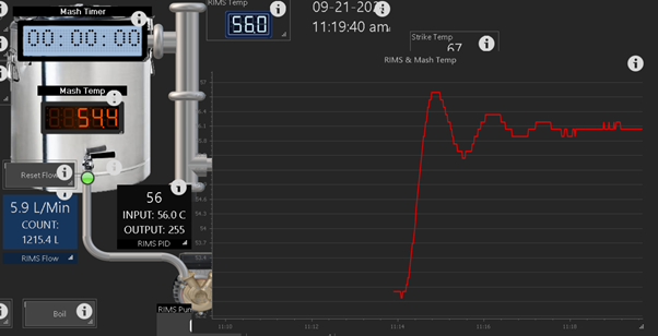
Finally I am ready, and I did my first PID tuning :) :


1600595410743.png
sqVq0_2ViPkOPHpxEAuyN8neBbT5pOpf5OmakV-3lHmgN1PdY4IXT63ZSEuUTzbIU_zlquYmg0aZ_t721wsgRtkdGv30FCcTBcTK5TfUlg3-_uhJ2WX7dnH31QVeHhW7rmgQsGxbjncvLR7S-e12KbJilSUtR1lNOHujzivA-KS-PBeCucONiKgToSdG7yBoyaozZvQ7iOrdi0bmSWE9E9ahHH2Hz73GU0BZyhA-_YetYPI8Q27LwVtBf7Ua5UO5hBSKo0O1v9p5TQYoA1GxA6Q1ZAGp7Ma2_bluKSzCL3BEIsScoxyAxJ6YxWJ2c_j9YLJZd7VBLY_wQNG-YNnH89uFExEoMK1tRvX-Ff4fS9hUDSNZ9GDA1Tb_acLfGN8J-YPV1niTaudM9eC8lo6HnD7ep-0uHYK4Cc4VtBcUmr1hJ_U8WXEbf9kJ0IMcpbFJpTq5cYzENP_-liRcV-qeb75t_YfKDNOnSArXMHUKDa0LxFgnsnM7eElfsgu-b8ZSH0IY34B9V12dYvQ0yengMYSk709nupRyNdhsUpuoOX6IADHJ9DJ4qSrySFmlXwqc0WzyArID8icLJ8-lOSVZrlPvW3KJOatDZWzhLpTN2CFwZBFRovHojlSDDzDVsr7RbTD60SBA0dHbHV24g9Gk1oCBZOQMJDssvjGj5cunK5q7ZKT7WNdImaYCbERInA=w1833-h1374-no
1600596211735.png
I

I think I should be ok with1st PID tuning - for my setup.
Flow was 2L/minute, 5, 0.1, 0 worked just fine. I am unsure if this is realyl good. Temp is within 0.1 deg from target temp. What do you think?
1600595673921.png


Cheers
 
Has anyone used a small PC like a Nuc or zbox to run BruControl? I was thinking of adding one inside my panel and adding a 22 to 24" touch monitor to one of the three cabinets and high voltage in one and low voltage in the other. I also wanted to use Ethernet jacks for the I/O to sensors and wanted to know if that has been done successfully or not.

I've used a mini PC with Atom processor. It's slow, but works. I mounted it to the back of the monitor via VESA mount. I use it to RDP to my BC server now, but its an option for direct control. I more recently bought a Celeron J4125 mini PC (noted above several pages), and it's a nice little unit at 8GB, 128GB SSD, with Win10 activated.
 
I do networking in my day job and I am pretty sure Cat5e and Cat6 are shielded and twisted pair inside so that should cut down the chance of picking up noise don't you think?

Just note that these are typically solid wire, so are prone to fracture with frequent bends. Otherwise, I think this wire can be successfully used.
 
I think I should be ok with1st PID tuning - for my setup.
Flow was 2L/minute, 5, 0.1, 0 worked just fine. I am unsure if this is realyl good. Temp is within 0.1 deg from target temp. What do you think?
View attachment 699243

Where is the temp probe here? I'm not surprised of the big swings if this is in the RIMs tube at this slow a flow rate. What is the blue line? What happened at the ~11:30 mark that caused the alignment to the blue line?
 
Where is the temp probe here? I'm not surprised of the big swings if this is in the RIMs tube at this slow a flow rate. What is the blue line? What happened at the ~11:30 mark that caused the alignment to the blue line?

At or a bit before 11:30, I changed target temp to 52C. System just followed my inputs.
Temp probe is just above heater, maybe 2cm or less above it. heater is 3.5 kW. System reacts quite fast after heater is on / or when it's pulsing.
With PID 20/ 1 / 5 swings are way to big for my system. Check the begining of the graph.

What would be the recommenderd flow rate?

I can increase it for sure, but then PID numbers will have to change. I was under impression that would be good flow :) maybe my conversion from imperial to metric failed again. 😢
 
Just note that these are typically solid wire, so are prone to fracture with frequent bends. Otherwise, I think this wire can be successfully used.
What 8 pin connectors are you using for panel I/O and what is their approximate cost? I sourced the Ethernet solution at approximately $1.70 per I/O connection and I am having difficulty locating 8 pin aircraft panel connectors as you site in the video.
 
They are inexpensive... off Amazon
At or a bit before 11:30, I changed target temp to 52C. System just followed my inputs.
Temp probe is just above heater, maybe 2cm or less above it. heater is 3.5 kW. System reacts quite fast after heater is on / or when it's pulsing.
With PID 20/ 1 / 5 swings are way to big for my system. Check the begining of the graph.

What would be the recommenderd flow rate?

I can increase it for sure, but then PID numbers will have to change. I was under impression that would be good flow :) maybe my conversion from imperial to metric failed again. 😢

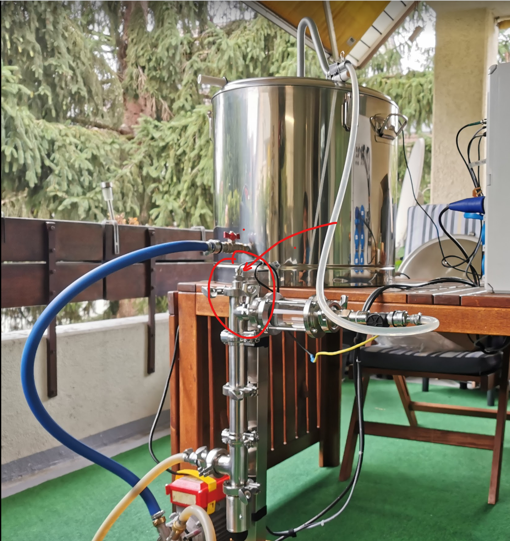
Are you saying the temp probe is in the RIMs tube? I'm saying the flow rate is very slow if you are at 2 lpm (1/2 gal/minute). This is about 2x sparge rate. In my rig, it flows as much as 6 gal / min (24 lpm) when the mash is fully settled. I would suggest at least doubling your flow rate to 4 lpm or more.
 
Are you saying the temp probe is in the RIMs tube? I'm saying the flow rate is very slow if you are at 2 lpm (1/2 gal/minute). This is about 2x sparge rate. In my rig, it flows as much as 6 gal / min (24 lpm) when the mash is fully settled. I would suggest at least doubling your flow rate to 4 lpm or more.

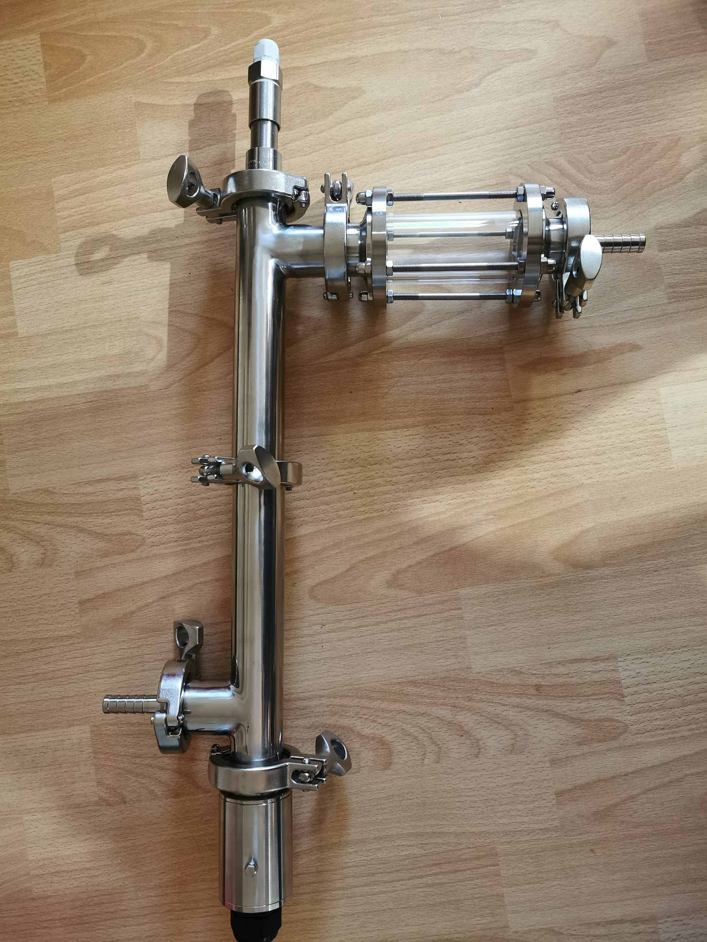
Yes it's in the RIMS tube at the top of it, where flow exits. Sensor (NTC) is inserted into thermowell at the top of the tube. I would estimate that thermowell goes almost to the top of the heater. Flow is passing sensor on the way out, and to the top of the mash.

I will double (or more) the rate and re test. I was reading somewhere it should be 1L/ min and that's freakigly slow. So thanks for the hints.
👍

1600620098936.png


1600619908695.png
 
Last edited:
Hi everyone,

Sorry for redirecting the topic, just want to share couple picture with you.
For past weeks and months, as I was building my setup and silently followed this group.
Finally I am ready, and I did my first PID tuning :) :


View attachment 699242
sqVq0_2ViPkOPHpxEAuyN8neBbT5pOpf5OmakV-3lHmgN1PdY4IXT63ZSEuUTzbIU_zlquYmg0aZ_t721wsgRtkdGv30FCcTBcTK5TfUlg3-_uhJ2WX7dnH31QVeHhW7rmgQsGxbjncvLR7S-e12KbJilSUtR1lNOHujzivA-KS-PBeCucONiKgToSdG7yBoyaozZvQ7iOrdi0bmSWE9E9ahHH2Hz73GU0BZyhA-_YetYPI8Q27LwVtBf7Ua5UO5hBSKo0O1v9p5TQYoA1GxA6Q1ZAGp7Ma2_bluKSzCL3BEIsScoxyAxJ6YxWJ2c_j9YLJZd7VBLY_wQNG-YNnH89uFExEoMK1tRvX-Ff4fS9hUDSNZ9GDA1Tb_acLfGN8J-YPV1niTaudM9eC8lo6HnD7ep-0uHYK4Cc4VtBcUmr1hJ_U8WXEbf9kJ0IMcpbFJpTq5cYzENP_-liRcV-qeb75t_YfKDNOnSArXMHUKDa0LxFgnsnM7eElfsgu-b8ZSH0IY34B9V12dYvQ0yengMYSk709nupRyNdhsUpuoOX6IADHJ9DJ4qSrySFmlXwqc0WzyArID8icLJ8-lOSVZrlPvW3KJOatDZWzhLpTN2CFwZBFRovHojlSDDzDVsr7RbTD60SBA0dHbHV24g9Gk1oCBZOQMJDssvjGj5cunK5q7ZKT7WNdImaYCbERInA=w1833-h1374-no
View attachment 699244 I

I think I should be ok with1st PID tuning - for my setup.
Flow was 2L/minute, 5, 0.1, 0 worked just fine. I am unsure if this is realyl good. Temp is within 0.1 deg from target temp. What do you think?
View attachment 699243

Cheers
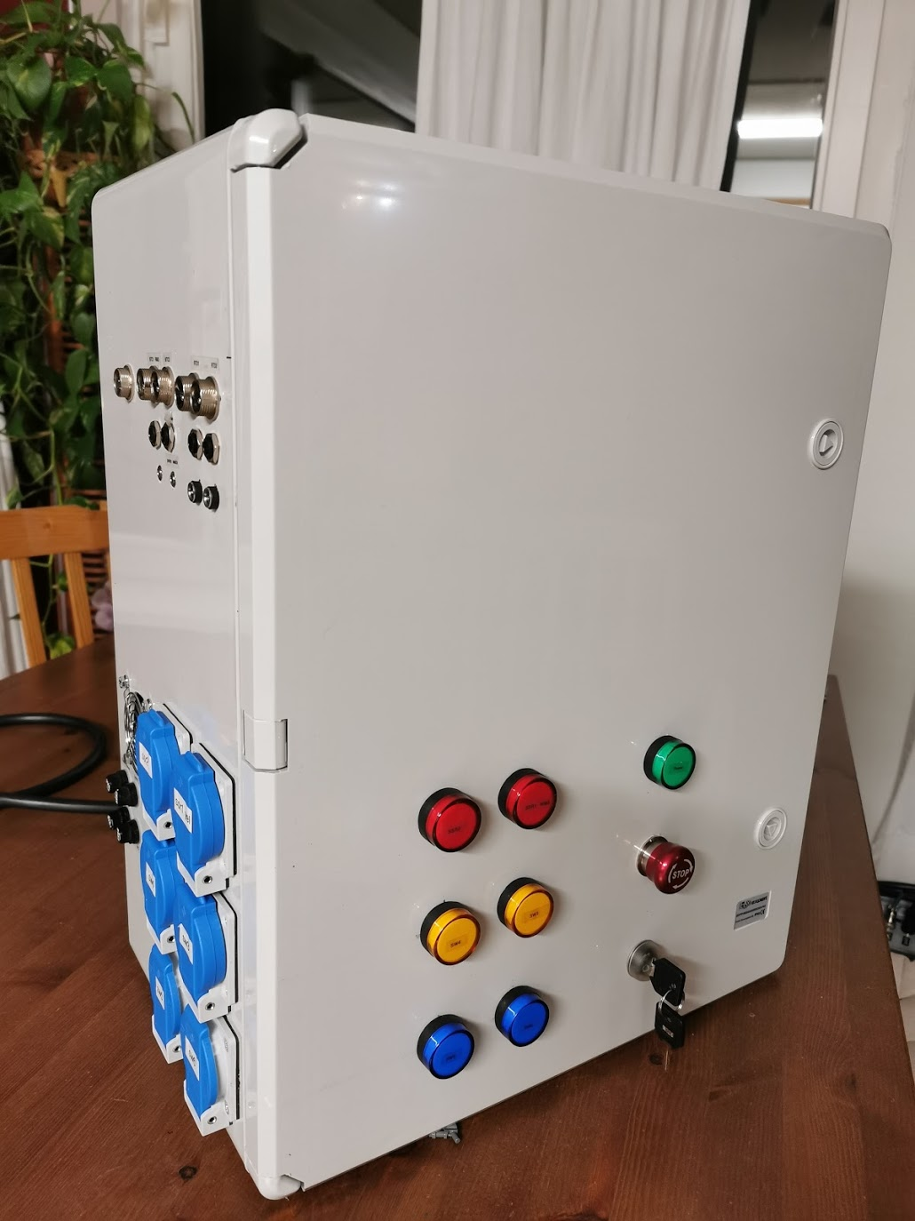
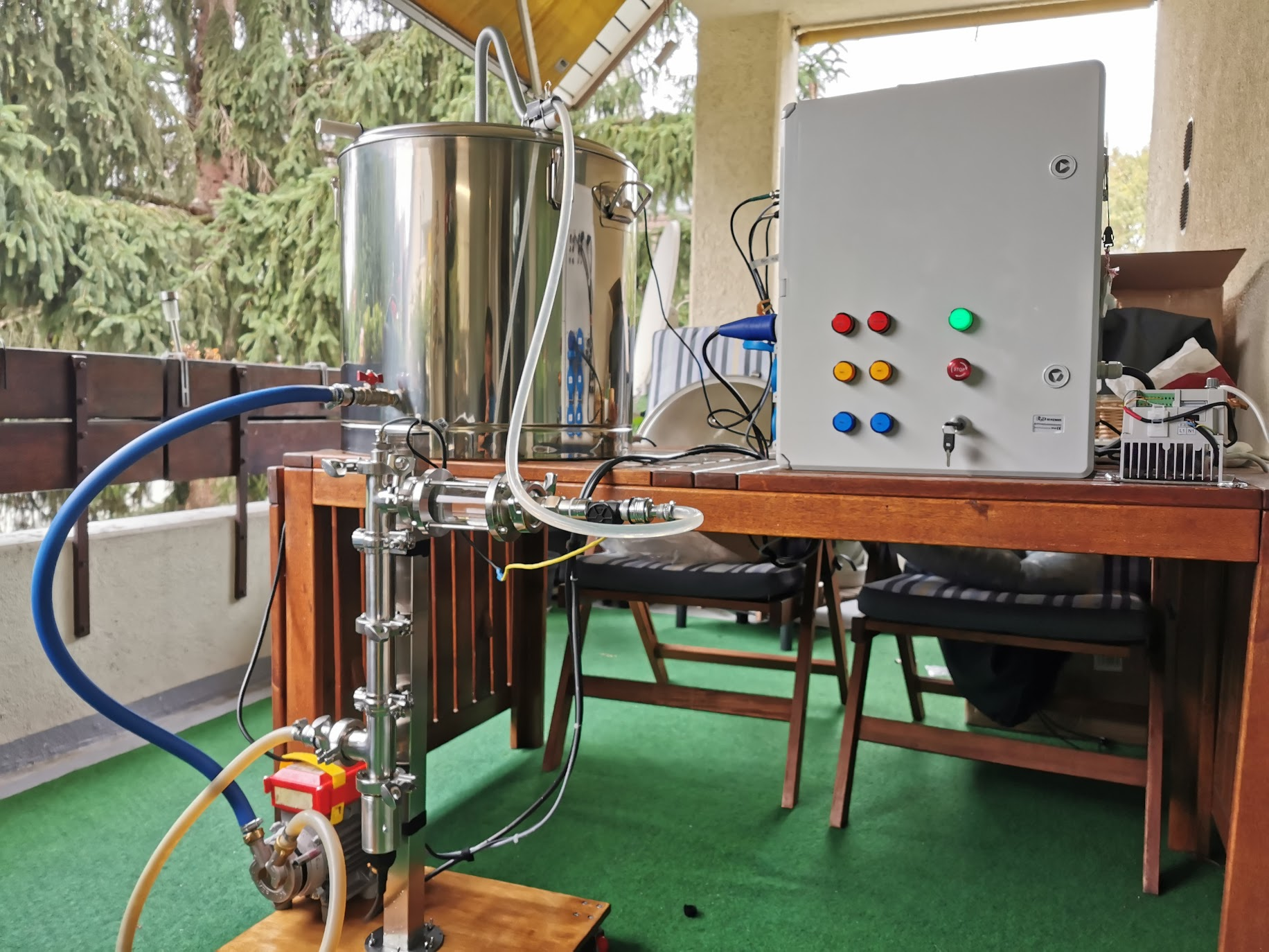
Would love to see more pictures of the inside of your panel! Looks great so far!
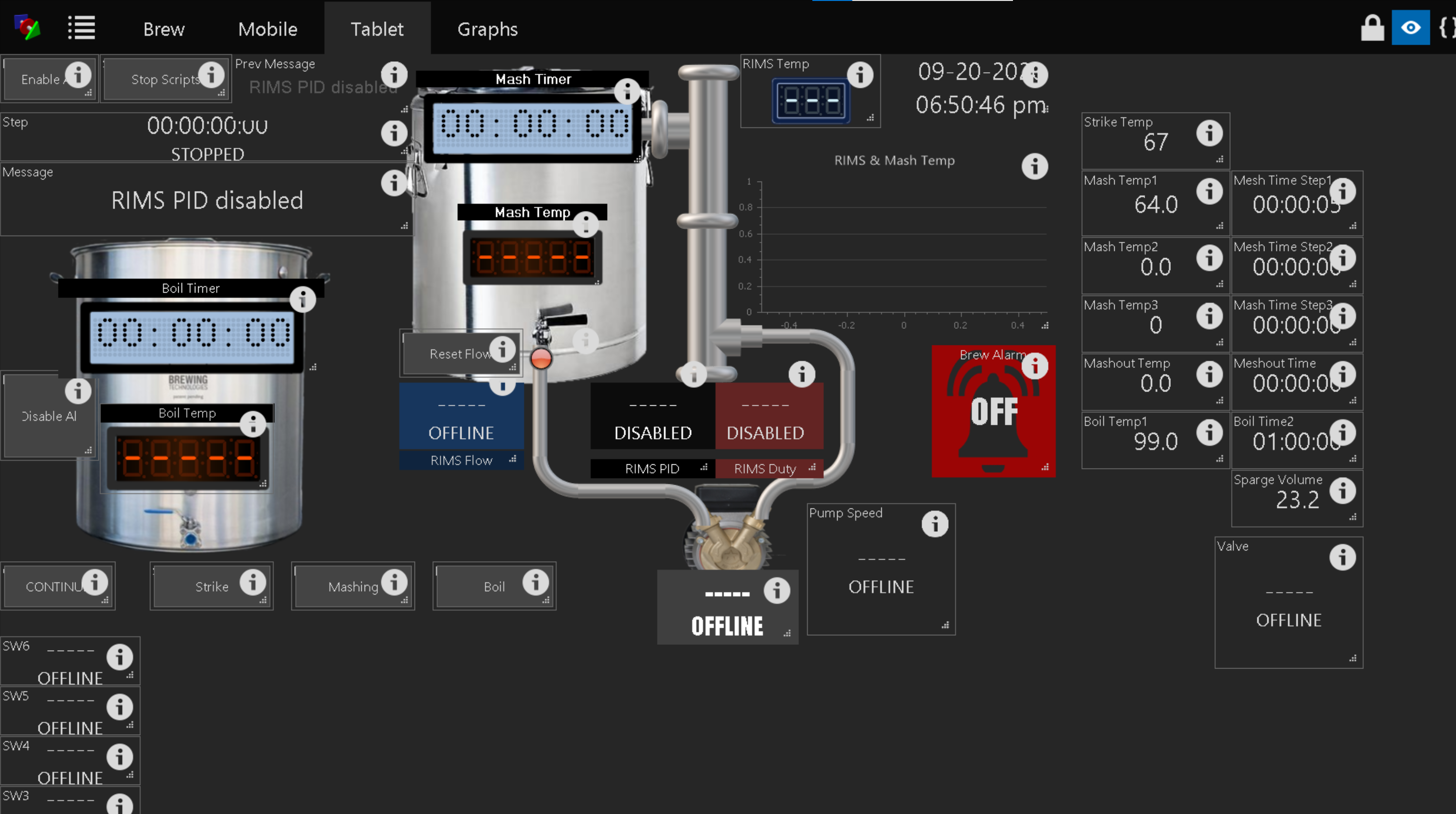
 
Would love to see more pictures of the inside of your panel! Looks great so far!
I managed to make my UI like this. I hope it helps, I know it's not "inside" :cool:
Please note I just started and I am learning, so this is for sure not final. Some of the devices, like Valve is just provisional, to be used in the future.
I really like to keep things simple :-D- if possible so no big automation scripts.
My aim is to enjoy brewing.

1600620666965.png


Enjoy brewing !!! :

1600620848583.png
 
Last edited:
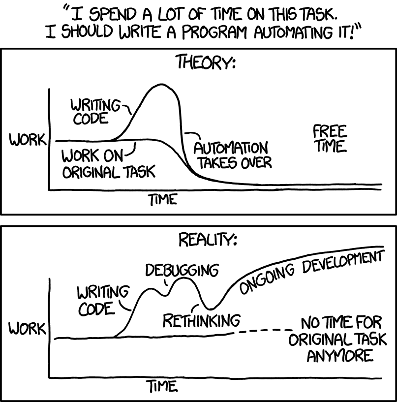
That graphic is so true!!

I assumed the issue was with the bootloader file (bootloader_qio_80m.bin), so I pulled down the latest bits from Github for the ESP32. I swapped the latest of bootloader_qio_80m.bin into the resources folder but had no luck with it. For grins, I then swapped the bootloader_dio_80m.bin in, modified the script, and now it seems to have loaded correctly. I'm not sure what the long term ramifications are of that, and I haven't tried flashing any of my older ESP32 boards with the current configuration. I'll be curious to see if you have the same issue with the 32E version as well.

Following up on this... I tried an ESP32.. 32E with the 45N firmware using the Universal Install tool and it worked correctly on the first try. So... not sure whats up with the unit you have.
 
Getting close to finalizing wiring diagram. Any suggestions?
 

Attachments

  • BC Panel Power Plan(1).png
    225.4 KB · Views: 16
Here is an updated diagram, cleaned up some stuff and separated by HV and LV panels..
 

Attachments

  • BC WIRING DIAGRAM - FINAL(1).png
    313.3 KB · Views: 19
Can someone tell me please what's the latest versions of firmware for MEGA and brucontrol software you are using ?

And how to download that pre-relesses or "beta" brucontrol and corresponding fw?

I've seen on the live video UI elements with enable disable slider on each and I like that a lot, but I don't have it 🙂.
Firmware updates can be found here

https://brucontrol.com/download/firmware
 
Last edited:
Are you saying the temp probe is in the RIMs tube? I'm saying the flow rate is very slow if you are at 2 lpm (1/2 gal/minute). This is about 2x sparge rate. In my rig, it flows as much as 6 gal / min (24 lpm) when the mash is fully settled. I would suggest at least doubling your flow rate to 4 lpm or more.
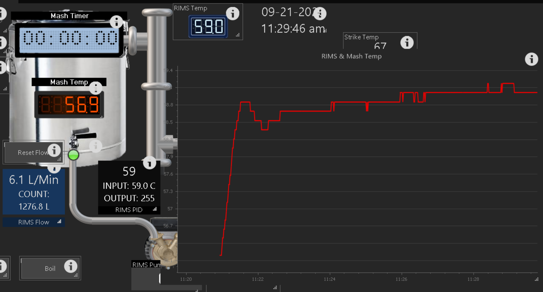
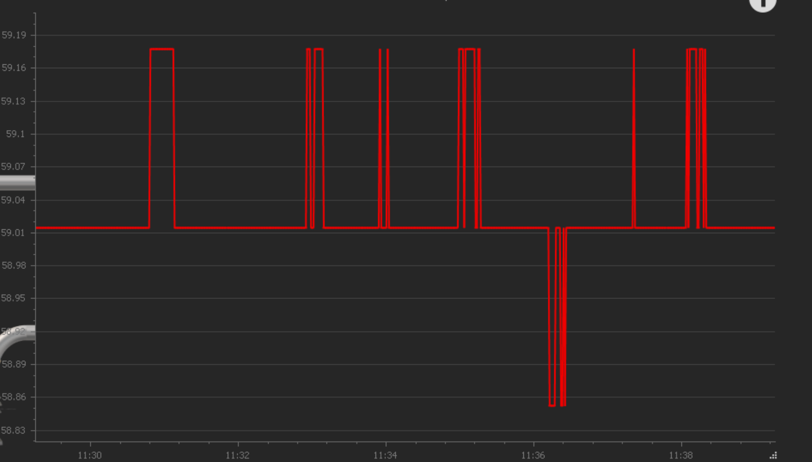
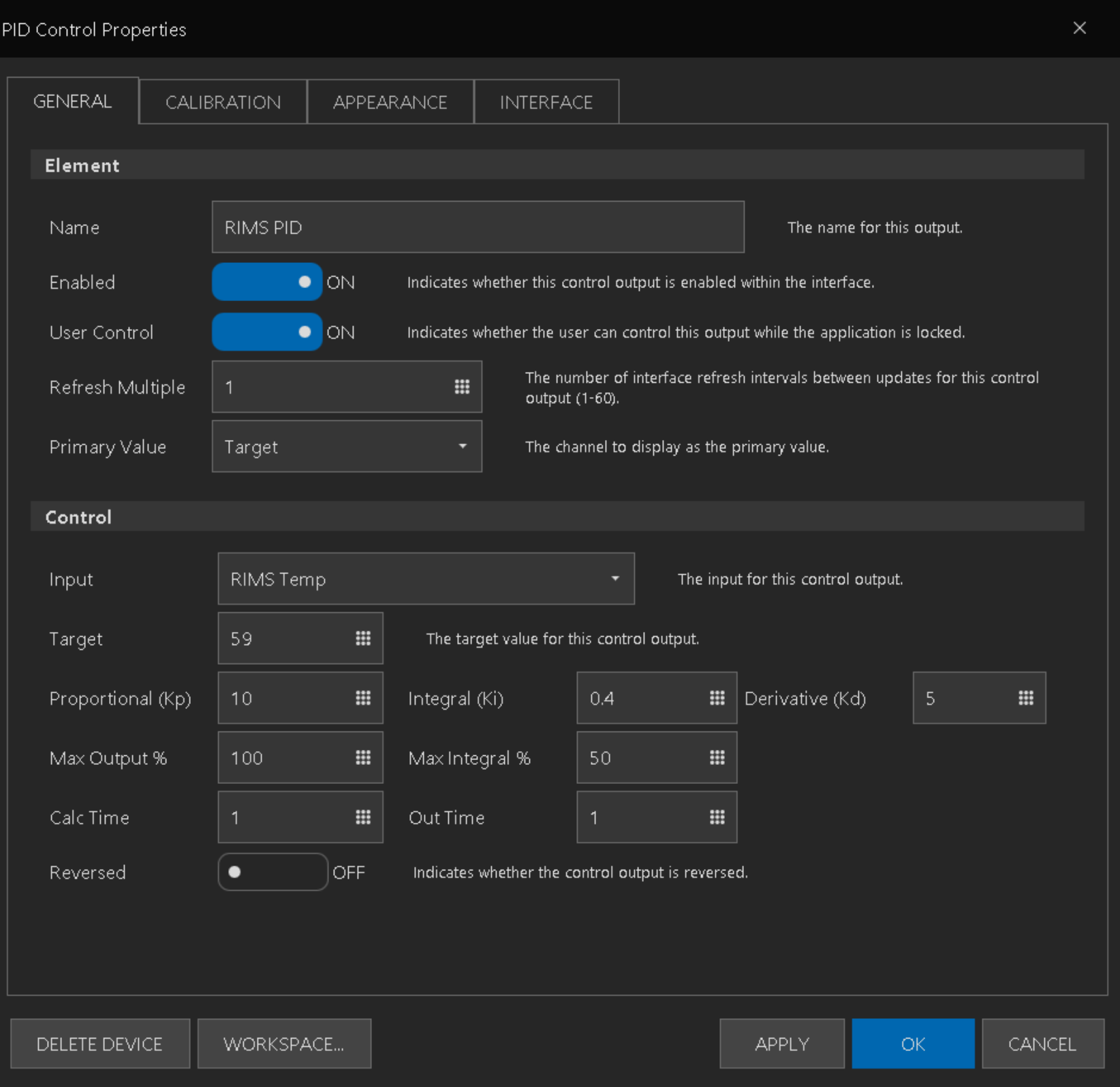
Hi there BrunDog and everyone,

What do you think about this PID parameters and graph?
Would you adjust it more or you think I am good to go and please if you have any suggestions, you are very welcomed, thanks in advance to everyone.

10 0.4 5 (PID) ; Flow was fairly stable for all tests at about 6 lpm
Measurement start > target Temp: 56->59C;
Graph size = 10 mins
RED graph line is RIMS Temp only - I have removed mash temp from the graph.
Pump speed 27.5Hz (45 digital input) - it's info for me - as I am using VFD to control flow speed.
1600680597566.png


when stabilized:
1600681170804.png
1600680652713.png


PS

________________________________________________________________
I did several other tests but I think above is the best candidate:

test 1 (without D)
11 0.4 5 (PID) ; Flow 6L/min Start > Target Temp: 52->56C;
Pump speed 27.5Hz (45 digital input)
1600680698985.png


test2 w/o D
13 0.1 0 39C->42C
1600680728825.png


test3, first time with D.
9 0.2 5(PID) ; Flow 6L/min Start > Target Temp: 45C -> 48C;
Pump speed 27.5Hz (45 digital input)
1600680785386.png
 
Last edited:
All of those look excellent. You have rapid convergence and you are down to the resolution of the probe. For example, your "When Stabilized" pic looks like big moves but they are only +/- ~0.2 C. In the beer world - I don't think it can or needs to get any better in my opinion. Nice job!
 
Following up on this... I tried an ESP32.. 32E with the 45N firmware using the Universal Install tool and it worked correctly on the first try. So... not sure whats up with the unit you have.

Interesting, I'm not sure what the issue is either then. Mine is an Espressif unit, but changing the bootloader definitely made it work. Oh well, its sorted either way if someone else has issues.
 
Still in the planning phase and updating my scripts.

The HLT will have two 220v Elements. In my old system, I only had one 220v Element and I used a 24vac SSR to control an Double Pole Electrical Contactor using Hysteresis. That way, there was not a Hot Leg waiting for a ground at the Element.

Since I will be running all new wire, I can run 10/4 AWG and use Nema 14-50 (I like the Larger Lugs) Plug and Receptacle and use something like a Crydom MCPC1250C and use PID Control as I will now have the extra Ground Safety. How do I do that with two Elements. After we reach temp, have one on Duty Cycle and the Other PID? Use the new Dual Throw control both as PID?

Or should I use the Electrical Contactor like before and Hysteresis for safety like before. Looking for some insight if someone is doing this.
 
I need some visual aid.
Is there a way to make element "flashing" by changing images ? Image 1-> 500ms pause -> image 2 -> repeat.

If I use script below it would stop at sleep 500:
[start]
"Alarm 1" Background = 1
sleep 500
"Alarm 1" Background = 2
goto start
or flash text message: "text" -> "nothing" -> text

Reason I am asking is issue I am having with passing sound through RDP client.
At least for me it is not reliable to pass sound from application, so it would be good to enforce the alarm with visual aid (through software)
 
Last edited:
You need another sleep 500 after you switch the alarm background to 2. Without a pause there, you are changing to 2 but immediately changing back to 1, so you never see it change.
yep that was it, thanks a lot ! I am confused a bit how sleep works with goto.
 
Sleep will always wait the time set at that line before advancing to the next line.
Goto will always immediately jump to the set place and execute the next line.

Just keep in mind that the BC interpreter can process thousands of lines of script per second (probably more), so if you need to *see* something happen on the screen, sleep and wait commands are your friends.

thanks. Your explanation make sense totally,

But why is code in this example below executed only once ?

[start]
"Alarm 1" Background = 1
"Alarm 1" Background = 2
sleep 500
goto start

Command 1 and 2 ("Alarm 1.....) will be executed but then it seems , script will be paused indefinitely at "sleep 500" . So no changes are visible after sleep. Only ones background switches.
I'd expect that that all lines will be executed in a sequence and sleep 500 will be exactly sleep 500, then cycle trough commands in endless loop , each pass stopped for 500 ms.

What is weird that following code works as you explained.
[start]
"Alarm 1" Background = 1
sleep 500
"Alarm 1" Background = 2
sleep 500
goto start

how's that? I have no clue.

and if I do:

[start]
"Alarm 1" Background = 1
"Alarm 1" Background = 2
goto start

I see the changes.... even without sleep.
 
For your first example, its not paused, its just that the 500ms wait is the longest wait in the script sequence and step one and two are executing so fast that its not displaying. Type "print 1" between your two alarm statements and you'll see that its still executing over and over in the output, with .5 seconds between print outputs.

In your final example, this is what is called a race condition where the system is executing the code as fast as it possibly can, its simply chance that its landing on one image or the other and it happens to be displayed on your screen. Keep the print 1 between the alarm statements and you'll see the output flooded at the microsecond level. While this appears to work, it needlessly consumes CPU cycles and will likely not work long if you put more statements like that in place.
 
I like to put a sleep command in any loop regardless. Without the sleep, sometimes it will not respond to a manual stop. As a habit, I always add

[Loop]
sleep 100
..rest of my code
goto Loop

A comment:

I would not use [start] or any other script command as a name of a section, ELEMENT or variable.

It works, but the goto start looks odd to me in the Script Window. goto AlarmLoop does not.

x.png


I would also add an if statement to get out of the alarm if you click it off:

//scrFlashing Alarm
[AlarmLoop]
"Alarm 1" Background = 1
if "Alarm 1" active == false
goto ExitAlarm
endif
sleep 500
"Alarm 1" Background = 2
if "Alarm 1" active == false
goto ExitAlarm
endif
sleep 500
goto [AlarmLoop
[ExitAlarm]
stop scrFlashingAlarm
 
Still in the planning phase and updating my scripts.

The HLT will have two 220v Elements. In my old system, I only had one 220v Element and I used a 24vac SSR to control an Double Pole Electrical Contactor using Hysteresis. That way, there was not a Hot Leg waiting for a ground at the Element.

Since I will be running all new wire, I can run 10/4 AWG and use Nema 14-50 (I like the Larger Lugs) Plug and Receptacle and use something like a Crydom MCPC1250C and use PID Control as I will now have the extra Ground Safety. How do I do that with two Elements. After we reach temp, have one on Duty Cycle and the Other PID? Use the new Dual Throw control both as PID?

Or should I use the Electrical Contactor like before and Hysteresis for safety like before. Looking for some insight if someone is doing this.

Sorry... I don't understand what you are asking or looking to do.
 
Sorry... I don't understand what you are asking or looking to do.
I am not sure how you would control two Elements in the same vessel. I assume that the Quadzilla use has some logic that you could use with that. If I understood the control logic of how to use the Quadzilla, I would know how to wire the new brewery for multiple Elements in the same vessel.

I guess I am looking for help with the logic (as well as what type of BruControl Element {PID,? Hysterisis?....?} for control of more than a single Element in the same vessel.

I am not sure if something like


pidHeaterElement1 state = True
pidHeaterElement2 state = True

is all the logic I need where I have two separate PID circuits and controls in the same vessel?

Or would having two PIDs reek logic havoc in the same vessel.

I looked into the new Dual Throw Port Property but it looks that is only for a Digital Output Element.


I was hoping someone was controlling two different heating Elements in the same vessel and trying to maintain a specific temperature. My issue is that a single Element was not sufficient on its own to maintain a Temperature in the Winter.
 
Back
Top