BruControl: Brewery control & automation software

Homebrew Talk - Beer, Wine, Mead, & Cider Brewing Discussion Forum

Help Support Homebrew Talk - Beer, Wine, Mead, & Cider Brewing Discussion Forum:

This site may earn a commission from merchant affiliate links, including eBay, Amazon, and others.
Hey just want to extend my most sincere THANK YOU to @highland_brewer for hosting me today on his live brew day!! He is the quintessential gentleman... as well as being a good multi-tasker. Most importantly, he manages surprises really well!!!

Here is the link again - check it out when you get a chance to see the UniFlex and BruControl in action:


Came and went a few times through out the brew day...was interesting learning about all the automation! Controller looked awesome!

Nice job as always @highland_brewer!
 
Hey just want to extend my most sincere THANK YOU to @highland_brewer for hosting me today on his live brew day!! He is the quintessential gentleman... as well as being a good multi-tasker. Most importantly, he manages surprises really well!!!

Here is the link again - check it out when you get a chance to see the UniFlex and BruControl in action:


You guys did a great job, it's hard keeping folks entertained for 3+ hours. Strong work @highland_brewer and @BrunDog
 
Can anyone share a cost effective wire and gauge recommendation for 24v dc solenoid valves about 50' run. Would this be three or two wire? Shielded?
 
wire size depends on the current carrying requirements. Can you post a link to the valve, or at least provide the steady current or power?

DC solenoids only require 2 wires... no shielding needed.
https://www.amazon.com/dp/B00DQ27IFO/ref=cm_sw_r_other_apa_i_YKzvFbMQSA4WV
This is what we have

On a side note I just read not to keep energized for 8hrs. How would I go about "checking" that the valve hasn't been open for x duration and allowing it to deenergize (to cool down) if it has? Via script that is
 
Last edited:
Can you share what you will be using them for? Solenoids use a lot of power and generate a lot of heat due to the large coil. If you are looking for good flow and don't care about actuation speed, a motorized ball valve is likely a better fit.

If not, this is easy to script.
 
Can you share what you will be using them for? Solenoids use a lot of power and generate a lot of heat due to the large coil. If you are looking for good flow and don't care about actuation speed, a motorized ball valve is likely a better fit.

If not, this is easy to script.
I'll be using them to control glycol to dual jacket 10bbl FVs plumbed in parallel. Also got a few 7bbl FVs with single jacket.

Solenoids are already purchased and I believe these are industry standard. Only see an issue with the energized duration during a cold crash
 
Yeah... you want flow. Go with motorized ball valves. You can leave them wherever you want for infinite time and no power draw.
Solenoids are already purchased and I believe this is industry standard. We will probably rock these for a while since we already have them and look to ball valves as an upgrade. We can pull wire large enough for whichever has the largest amp draw.
 
The draw ~850 mA each. This is low voltage so no sill rules around conduit, etc. I would go with 22 AWG. Will easily carry the current, have some durability, and won't break the bank. Look for 2 conductor, stranded, with PVC jacket.
 
The draw ~850 mA each. This is low voltage so no sill rules around conduit, etc. I would go with 22 AWG. Will easily carry the current, have some durability, and won't break the bank. Look for 2 conductor, stranded, with PVC jacket.
Thanks, much appreciated.
 
Thanks, much appreciated.
I would use 18 awg myself just in case I add something later that might require a higher amperage. Bigger is better for the most part (as long as not two big.) You would be fine even with 22 awg. I would definitely second going with ball valves. The Glycol does not need to be exchanged all the time. It stays cold for a while. Regardless, you could easily write a script where the valve is open for fifteen minutes on the five minutes off then fifteen minutes on the five minutes off then fifteen minutes on the five minutes off then.....

You would never exceed the 8 hour limit.
 
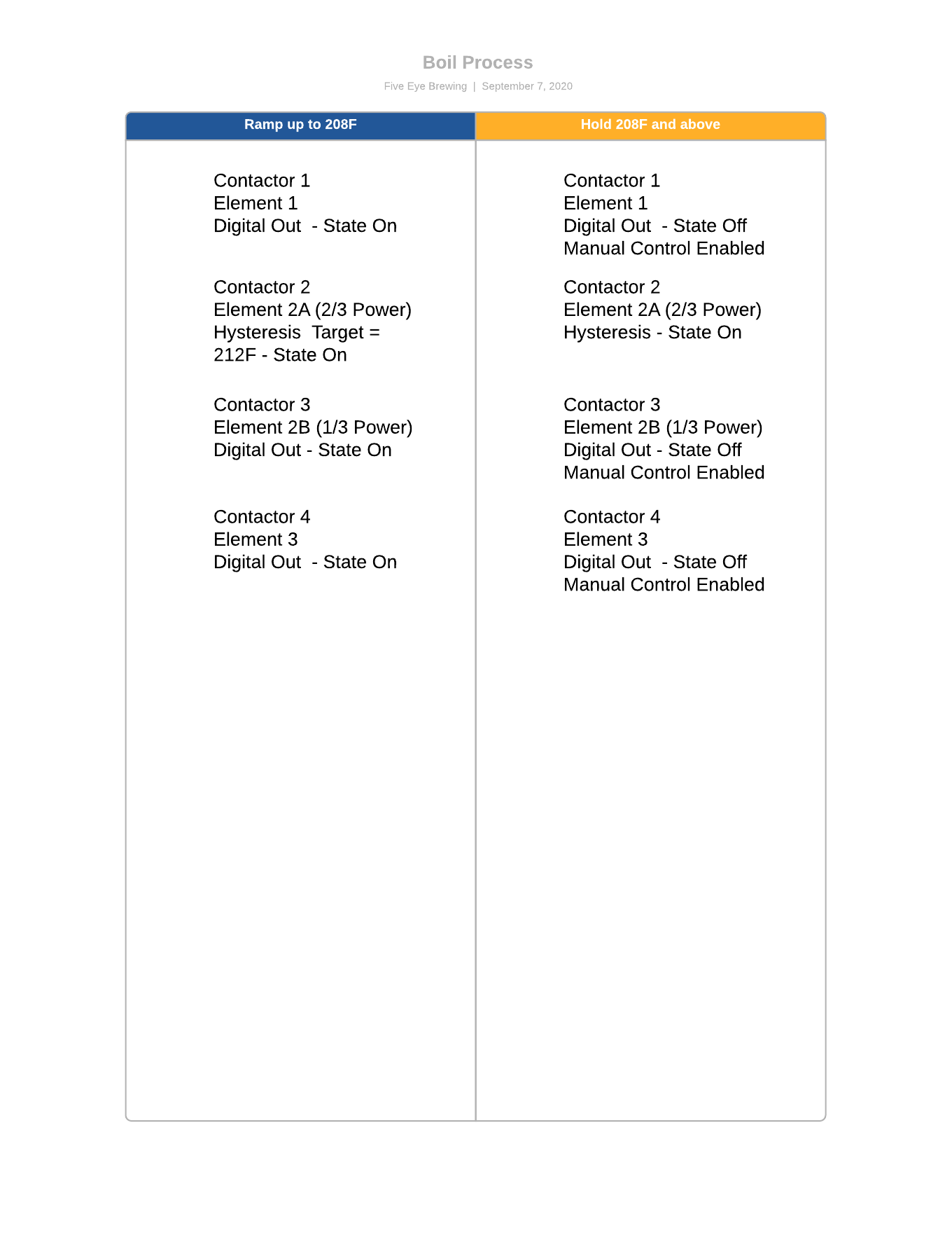
I currently have (4) 50a contactors controlling (3) 12kW heat elements, all in kettle.

Contactor 1 controls Element 1 via digital out
Contactor 2 controls Element 2 (1/3 Power) via digital out
Contactor 3 controls Element 2 (2/3 Power) via hysteresis
Contactor 4 controls Element 3 via digital out

If Contactor 2 and 3 are energized I get full power to Element 2.

During ramp phase, all elements will be 100% power. When I near boil over temps (208F or so), I plan to have BC automatically shutoff Element 1 and 3 and allow manual control of Element 2. Either 4kw, 8kw or 12kw (via Element 2), 16kw (adding Element 1 or 3).

I plan to have Contactor 3 controlled via hysteresis with a set point of 213. In script, I reference a boil offset global which defines a value of 208F. So if measured value is less than 208F, all contactors are live. If 208F is achieved, all Contactors are off except for Contactor 3 since 213 cannot be achieved. At a reduced power and no chance of boil over I want the operator to take over and begin turning on elements manually to achieve desired boil. This will likely be Contactor 2 for a total of 12kW. I thought a Low/High switch would be neat for Element 2. Need to actually boil our first batch to see if manual control of Element 1 or 3 is needed.

Looking for some improvements/ideas to the above.. I'm sure most of you are using SSRS at 5kW or so. Wanted to keep heat and component pricing down. I understand how much easier this would be with them!


Boil Process.png
 
Last edited:
Hey all,

Here is one for the brain trust. I have been running this setup for about a year now and I keep having this persistent error in a script that I only see after everything is done. The script runs fine, and the brewing doesn't have a problem.

In the subroutine I use to control the mash temperature ramping, I always get a
"12:48:22.668 [ERROR: cannot return, call history empty]"

but I can't for the life of me figure out why. Here is the subroutine that is running.
Code:
[MashRamp]
//control the ramping of the HLT temp to run up the mash temp
if "MT_Temp" Value < "MT_Target" Value
    scriptTemp1 = "MT_Target" Value - "MT_Target_Backoff" Value 
    if "MT_Temp" Value <= scriptTemp1
        print "Chasing Temp"
        print scriptTemp2
        "HLT PID" Target = "MT_Temp" Value + "MT_Ramp_Delta" Value // chase the temp up
    else 
        "HLT PID" Target = "MT_Target" Value + "HLT_SS_OS" Value // set to steady state value
    endif
    sleep 10000
    goto "MashRamp"
endif          <--------------------Error is here-------------------
return

The thing that seems odd is that it runs fine for the whole mash and the control moves on past the end of the mash sequence and the brewing runs as expected. I don't like having errors, so I'm trying to figure out why this is happening. I figured if this error happened it would terminate (pause) the script and I would have to fix it before I could have the automation run through, but it runs fine and I just see the status of that script as "Paused" instead of Stopped after a brew day.

Any thoughts?
 
I'm guessing that the goto loop is negating the call function (assuming you are calling the MashRamp routine from somewhere else). If you aren't calling the routine from somewhere else, just comment out return and I'd bet it runs fine.
 
The goto loop should just keep it in the loop until the temperature is above the target. So on the last loop through, it should hit the goto and then start at the "if" at the top, jump to the endif and then return. This is what it does for the 6 steps of the mash profile, and I have watched it running the loop and it looks correct.

Here is the code that calls it.
Code:
//step 6
if Step6_En State == True
    StepComplete Active = False
    "Recirculate_FlowRate" Value = "Recirc Rate 6" Value
    Status Value = "Ramping to Step 6"
    "MT_Target" Value = "Step6_Temp" Value
    call "MashRamp"  //let the ramping subroutine do its thing and then return
    "HLT PID" Target = Step6_Temp Value + HLT_SS_OS Value
    Status Value = "Step 6 Rest"
    start "Step6_Time"
    wait StepComplete Active == True
    stop "Step6_Time"
    //end step 6
endif
 
I currently have (4) 50a contactors controlling (3) 12kW heat elements, all in kettle.

Contactor 1 controls Element 1 via digital out
Contactor 2 controls Element 2 (1/3 Power) via digital out
Contactor 3 controls Element 2 (2/3 Power) via hysteresis
Contactor 4 controls Element 3 via digital out

If Contactor 2 and 3 are energized I get full power to Element 2.

During ramp phase, all elements will be 100% power. When I near boil over temps (208F or so), I plan to have BC automatically shutoff Element 1 and 3 and allow manual control of Element 2. Either 4kw, 8kw or 12kw (via Element 2), 16kw (adding Element 1 or 3).

I plan to have Contactor 3 controlled via hysteresis with a set point of 213. In script, I reference a boil offset global which defines a value of 208F. So if measured value is less than 208F, all contactors are live. If 208F is achieved, all Contactors are off except for Contactor 3 since 213 cannot be achieved. At a reduced power and no chance of boil over I want the operator to take over and begin turning on elements manually to achieve desired boil. This will likely be Contactor 2 for a total of 12kW. I thought a Low/High switch would be neat for Element 2. Need to actually boil our first batch to see if manual control of Element 1 or 3 is needed.

Looking for some improvements/ideas to the above.. I'm sure most of you are using SSRS at 5kW or so. Wanted to keep heat and component pricing down. I understand how much easier this would be with them!


View attachment 697295
So do you actually have (3) 4kW elements which can sum to 12kW? 12kW at 240V takes your current draw to 50A, doesn't leave much of a safety margin.
 
So do you actually have (3) 4kW elements which can sum to 12kW? 12kW at 240V takes your current draw to 50A, doesn't leave much of a safety margin.
The elements are 12kw a piece at 208 3 phase. We will wire delta and run 2 phases through one contactors and the third phase through another. So we can get 4kw, 8kw or 12kw from the one elements. The other two elements are wired delta three phase through a single contactor so full blown on those
 
Things seem to be much better using the power jack on Mega. Time to hook everything back up.
 
I currently have (4) 50a contactors controlling (3) 12kW heat elements, all in kettle.

Contactor 1 controls Element 1 via digital out
Contactor 2 controls Element 2 (1/3 Power) via digital out
Contactor 3 controls Element 2 (2/3 Power) via hysteresis
Contactor 4 controls Element 3 via digital out

If Contactor 2 and 3 are energized I get full power to Element 2.

During ramp phase, all elements will be 100% power. When I near boil over temps (208F or so), I plan to have BC automatically shutoff Element 1 and 3 and allow manual control of Element 2. Either 4kw, 8kw or 12kw (via Element 2), 16kw (adding Element 1 or 3).

I plan to have Contactor 3 controlled via hysteresis with a set point of 213. In script, I reference a boil offset global which defines a value of 208F. So if measured value is less than 208F, all contactors are live. If 208F is achieved, all Contactors are off except for Contactor 3 since 213 cannot be achieved. At a reduced power and no chance of boil over I want the operator to take over and begin turning on elements manually to achieve desired boil. This will likely be Contactor 2 for a total of 12kW. I thought a Low/High switch would be neat for Element 2. Need to actually boil our first batch to see if manual control of Element 1 or 3 is needed.

Looking for some improvements/ideas to the above.. I'm sure most of you are using SSRS at 5kW or so. Wanted to keep heat and component pricing down. I understand how much easier this would be with them!


View attachment 697295

I think you are going to have to try this to see what works and what doesn't. Without SSRs handling rapid switching, you are indeed relying on the combination of elements to get the boils you want. I would also suggest you play with a certain degree of kettle lid closure - that will drive a great degree of boil intensity for a given power level. Kettle insulation too, I s'pose.
 
I think you are going to have to try this to see what works and what doesn't. Without SSRs handling rapid switching, you are indeed relying on the combination of elements to get the boils you want. I would also suggest you play with a certain degree of kettle lid closure - that will drive a great degree of boil intensity for a given power level. Kettle insulation too, I s'pose.
Will do. Does my proposed setup with BC seem like a good start?
 
I would prefer you had SSR's so that you could have a finer degree of control. Ambient temp and pressure changes, volume differences, wort SG's will all affect the boil - and you may end up in a situation where you have a lion or a lamb of a boil, but nothing in between. Hysteresis will never trigger off at a 213 temp (assuming your probes are accurate)... so I'm not sure how this will work. Boiling is a straight up power game that is not dependent on temperature - the amount of power put in determines the amount of volume's phase change aka boil amount.
 
I would prefer you had SSR's so that you could have a finer degree of control. Ambient temp and pressure changes, volume differences, wort SG's will all affect the boil - and you may end up in a situation where you have a lion or a lamb of a boil, but nothing in between. Hysteresis will never trigger off at a 213 temp (assuming your probes are accurate)... so I'm not sure how this will work. Boiling is a straight up power game that is not dependent on temperature - the amount of power put in determines the amount of volume's phase change aka boil amount.
I was hoping the element split by 4, 8 and 12 kw was enough to determine the lion and the lamb. Know of any cost effective 50a 3phase SSRs?
 
Last edited:
Not sure what qualifies as cost effective for you, but this ain't too shabby IMO at a about a C note: https://www.digikey.com/product-detail/en/industrialemart/SR2-1250/2371-SR2-1250-ND/13148029

Edit: Here is one for $60... caveat emptor: https://www.amazon.com/dp/B01JI40VUM/ref=cm_sw_em_r_mt_dp_uuewFbHKXKGMM
Or another with heatsink and fan: Robot Check
Those aren't too bad. Maybe I'll run contactors up to 208F then have one or two elements on SSR.

Put me down for a Large Short Sleeve. Love the saying.
 
I am still in the planning phase of my replacement brewery. I do have some electric kettles but my two brew kettles will be propane or natural gas because that it what I prefer.

If I resort to low pressure and use furnace valves, how do you integrate with BruControl.
Something like this:


https://www.amazon.com/Rodgers-36H6...07M85SY16/ref=cm_cr_arp_d_product_top?ie=UTF8
I know some like not having gas, but I like gas for a brewery.
 
I think you should go electric unless you need to brew really big volumes and/or don't have access to the 240VAC power required. Ok, said my peace and I hear you want gas...

I assume that valve uses a power input of some sort (I didn't investigate wiring). So how you control it depends on the voltage required. If AC, you could use an SSR or electromechanical relay. If DC you can use a MOSFET / UniShield output, or an electromechanical relay. Either way you will need the power supply which lines up with the requirement for the valve. Once you have it, you can use Hysteresis, Deadband, or a script to control it. I'm not sure how you control the heat for the boil. If the valve's output can be lowered electronically, then good. If not, you will have to dial it down manually, or use a pair of valves (both on for full power, only one on for boil).
 
Everything ran fine for approx 24hr period wired 12v through jack. Lost connection shortly after. Only component wired was the RP-3 board (with 4 amplifiers) powered from 5v pin. Basically the Ethernet board lights change, it blinks it's lights rapidly different from a healthy connection.

Any known issues with RP3 and or amplifiers? Any suggested tests/ diagnosis?
 
Last edited:
I found a screw terminal for an ESP32, but its the DevKitC version, so I picked up one of those boards as well.

PXL_20200910_134214734.jpg

When I flashed it, it appears to have flashed normally, but in the debug terminal it looks like its stuck in a boot loop. Does a new firmware need to be cut for the DevKitC variants? I can get more logs if you need them.

Edit: I flashed attached and detached from the shield, same result. I tried both 45L/N with the same result.

Code:
esptool.py v2.6-beta1
Serial port COM3
Connecting........_
Chip is ESP32D0WDQ5 (revision 1)
Features: WiFi, BT, Dual Core, 240MHz, VRef calibration in efuse, Coding Scheme None
MAC: fc:f5:c4:3c:4f:24
Uploading stub...
Running stub...
Stub running...
Changing baud rate to 921600
Changed.
Configuring flash size...
Auto-detected Flash size: 4MB
Compressed 8192 bytes to 47...
Wrote 8192 bytes (47 compressed) at 0x0000e000 in 0.0 seconds (effective 3120.8 kbit/s)...
Hash of data verified.
Compressed 17664 bytes to 11528...
Wrote 17664 bytes (11528 compressed) at 0x00001000 in 0.2 seconds (effective 929.7 kbit/s)...
Hash of data verified.
Compressed 1423664 bytes to 837158...
Wrote 1423664 bytes (837158 compressed) at 0x00010000 in 12.6 seconds (effective 901.1 kbit/s)...
Hash of data verified.
Compressed 3072 bytes to 143...
Wrote 3072 bytes (143 compressed) at 0x00008000 in 0.0 seconds (effective 1170.3 kbit/s)...
Hash of data verified.

Leaving...
Hard resetting via RTS pin...

Code:
rst:0x3 (SW_RESET),boot:0x13 (SPI_FAST_FLASH_BOOT)
configsip: 0, SPIWP:0xee
clk_drv:0x00,q_drv:0x00,d_drv:0x00,cs0_drv:0x00,hd_drv:0x00,wp_drv:0x00
mode:DIO, clock div:1
load:0x3fff0018,len:4
load:0x3fff001c,len:1100
load:0x40078000,len:10088
load:0x40080400,len:6380
entry 0x400806a4
ets Jul 29 2019 12:21:46
 
Last edited:
Everything ran fine for approx 24hr period wired 12v through jack. Lost connection shortly after. Only component wired was the RP-3 board (with 4 amplifiers) powered from 5v pin. Basically the Ethernet board lights change, it blinks it's lights rapidly different from a healthy connection.

Any known issues with RP3 and or amplifiers? Any suggested tests/ diagnosis?

Ethernet and the RP-3 both use the SPI bus for communications. If there is noise on the line, for example induced by the wiring to the RP-3, it could disrupt the Ethernet communications. I don't recall your build directly, but if your interface and RP-3 are not right next to each other, this could be happening. I'll go back and look for a picture.

Edit: Went back to look for a picture. I would suggest sliding your RP-3's to the right to be as close to the MEGA as possible, and trim the wires down as short as possible. Also consider twisting them to help reduce noise pickup.
 
I found a screw terminal for an ESP32, but its the DevKitC version, so I picked up one of those boards as well.

View attachment 697745

When I flashed it, it appears to have flashed normally, but in the debug terminal it looks like its stuck in a boot loop. Does a new firmware need to be cut for the DevKitC variants? I can get more logs if you need them.

Edit: I flashed attached and detached from the shield, same result. I tried both 45L/N with the same result.

No, DevKitC is what we use quite a lot. Make sure the buttons aren't stuck closed. Otherwise I'm not sure why its looping. Do you have another one on hand?

Nice to see a shield for this.
 
Ok, I'll mess with it a bit more. I don't have another on hand that isn't already flashed and the DevKitC variants seem to be a bit wider than the other boards so they wouldn't fit the shield anyway.
 
No dice on flashing, buttons are not closed and they respond as expected when pressed. I tried manually putting the board in flash mode but it didn't make a difference. The variant I have is a ESP32-WROOM-32E, these were released this year, possibly as recently at June. This appears to be a new chip (ESP32-D0WD-V3) from previous gen ESP32-WROOM-32D. https://www.espressif.com/sites/default/files/documentation/ESP32_ECO_V3_User_Guide__EN.pdf

Do you have any 32E boards? I don't think this board is a dud since I can flash other sketches to it.
 
Well, it installed a sketch correctly one time, now its doing the same thing with the constant boot loop... I'll send it back and get a new one and we'll see what happens.
 
Now I'm at a loss... using the Arduino IDE 1.8.13 in Ubuntu, I changed the flash mode from the default QIO to DIO and now it will load sketches properly. Using the esptool.exe program in Windows, it gives the boot error. I'll look further into the flags set in the InterfaceSetup script and see if anything jumps out.
 
Ethernet and the RP-3 both use the SPI bus for communications. If there is noise on the line, for example induced by the wiring to the RP-3, it could disrupt the Ethernet communications. I don't recall your build directly, but if your interface and RP-3 are not right next to each other, this could be happening. I'll go back and look for a picture.

Edit: Went back to look for a picture. I would suggest sliding your RP-3's to the right to be as close to the MEGA as possible, and trim the wires down as short as possible. Also consider twisting them to help reduce noise pickup.
What picture you looking at? My RP3s are directly above Mega pretty close actually
 
Back
Top