• Please visit and share your knowledge at our sister communities:
  • If you have not, please join our official Homebrewing Facebook Group!

    Homebrewing Facebook Group

BruControl: Brewery control & automation software

Homebrew Talk

Help Support Homebrew Talk:

This site may earn a commission from merchant affiliate links, including eBay, Amazon, and others.
Not sure I'm following on the reset... if you know the times, assuming you are using a script, just issue a "timer1" value = "00:04:35" after a wait command looking for the 1:15 timer to hit 00:00:00.

You don't need to stop the timer to give it a new time.
Worked good. I just had a lesson. I deleted about 5 scripts of lots of lines trying to figure out what you can do with 3 lines.
rivercity.png
 
Last edited:
They are G 1/2"?
They are G 1/2 flat seal with a special gasket. Not sure you need this... but not sure if I want to try it without. They have other options for about $70 with the adapters installed, and the M12

Also, what size power supply are yall running? I just need enough 12V juice to run the Mega, but a larger 5V to drive the relays and power the amplifiers? I know this is I/O dependent.... I will have 4 relays, 2 SSR, 3 RTDs, and a flow meter to start. I will likely add more RTDs or temperature probes to this panel. Valves will be done via remote IO.

Just trying to get the panel laid out before buying.
 
Last edited:
I would avoid using 12V to power any Arduino. 9V is the sweet spot, 12V just shortens the on-board 5V linear regulator's life span...

Came across this the other day

https://www.robotshop.com/media/files/pdf/datasheet-ethermega.pdf

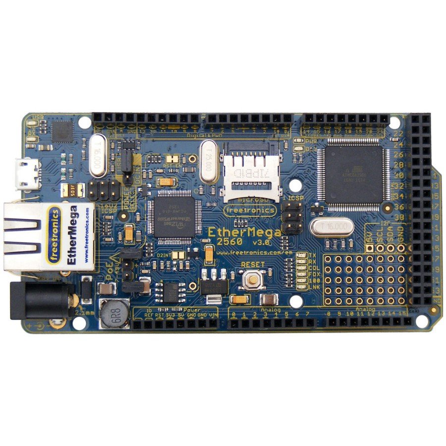
Apparently this has a switchmode regulator and can run input voltages up to 28VDC and not have the overheat problems some 12V versions have.
I'm using their earlier version which has an onboard W5500 but looks like they changed it to the W5100 with the newest version.
Agree with @day_trippr 12VDC can cause overheating/stability problems and eventually regulator failure. I had to back down the power input to 5VDC (from 12V) and now power through the micro USB which remedied both problems.
 
Last edited:
I have two power supplies, a 12V and a 5V.

12V 1.68A:
https://www.amazon.com/gp/product/B00DECZVY6/ref=ppx_yo_dt_b_search_asin_title?ie=UTF8&psc=1

5V 3A:
https://www.amazon.com/gp/product/B005T6RBSO/ref=ppx_yo_dt_b_search_asin_title?ie=UTF8&psc=1

The 5V has maybe 12 relays, the Mega + ethernet, two flow meters, two fans, and a few sensors (mA size stuff). The 12V runs 8 motorized ball valves, two solenoid CO2 purging valves, a couple pressure sensors, and two 4-20mA transmitters. The 12V isn't big enough to run all the ball valves and/or the solenoids at once so I just have the software sequence them two at a time and that is fine. The 5V had loads of margin, I could run a lot more off of that.
 
Id like to setup a static IP for ethernet shield Wiznet 5100/5500. Can someone point me in the right direction to doing so? I know how to configure router but prefer to assign IP direct to Wiznet in the event of router failure.
 
Oh yeah... forgot about those. Need the NPT pipe adapters with the unit. Makes it quite a bit longer but still... needed!
I looked at those IFM's, but the special threaded union connectors looked to cost more than the units... let us know if you get them at a good price...
I was able to pick up two of them for $55 each with three NPT adapters. I don't have them hooked up to BruControl yet, but they work great to monitor my fly sparge flow rates.
 
I have two power supplies, a 12V and a 5V.

Similar here, a 9v supply just for one board is just nonsense. Not even going to argue that, it is just silly...

I have a 12V that powers the 2-10v signal for the analog amplifier board and a 24VDC for the industrial automation things, and a a 24VAC transformer for my Johnson proportional control valves. Adding a 4th power supply is something I will fight very hard.

IMHO, a din-rail screw shield with an installed (or just the traces to install) a $1 buck-boost converter seems to be the logical solution ...

I was scratching my head to installing a 12V and 5V power supply when everything in the cabinet uses 5V on the control side.

My plan is to install the 12V power supply in a smaller box to control valves. I also have one of these laying around... https://www.amazon.com/gp/product/B01MEESLZ6/ref=ppx_yo_dt_b_search_asin_title?ie=UTF8&psc=1
 
Id like to setup a static IP for ethernet shield Wiznet 5100/5500. Can someone point me in the right direction to doing so? I know how to configure router but prefer to assign IP direct to Wiznet in the event of router failure.
You need the shield to the audrino then run the firmware interface setup but choose option 2. Use the termite program to set up.
 
I am getting one of the 5vdc din rail PSU.
https://www.amazon.com/gp/product/B005T6RBSO/ref=ppx_yo_dt_b_search_asin_title?ie=UTF8&psc=1
I have been using a buck transformer but think the PSU is a better choice.

I just ordered the ethermega ($$) and it says it can take up to 28 vdc input!
My 12 vdc wall wart should handle that fine!

https://www.robotshop.com/media/files/pdf/datasheet-ethermega.pdf
I am hoping that the micrusb is more robust than the robodyn mega with ethernet. I have 2 of those that I can no longer get the usb to connect.
 
I just ordered the ethermega ($$) and it says it can take up to 28 vdc input!
My 12 vdc wall wart should handle that fine!

When you receive your new MEGA could you report back if there is any physical differences with the regulator. I'm wondering if they have used a beefier regulator or used a big heat sink on it to allow for it to run cooler with the increased power?
Also if it still requires the jumper removal to enable the onboard Ethernet. Like you I have the original RobotDyn MEGA but with mine, stability issues were caused by powering it with 12VDC and overwhelmed the regulator. Looks promising, maybe this is a more robust board all around?
Best of luck with it hope it works out well for you!!
 
Makes sense Thank you.

What are the trays that hold the wires called? Id like to purchase a few of these for keeping wires nice.

Does anyone have any examples of fermentation script? I'd like a fully automatic fermentation from pitch to cold crash but with user overrides for things like d rest and cold crash.
 
Does anyone have any examples of fermentation script? I'd like a fully automatic fermentation from pitch to cold crash but with user overrides for things like d rest and cold crash.

Way back on Post #497 for a starting point.
 
When you receive your new MEGA could you report back if there is any physical differences with the regulator. I'm wondering if they have used a beefier regulator or used a big heat sink on it to allow for it to run cooler with the increased power?[...]

You can see that this board no longer sports the three terminal linear regulator between the barrel socket power connector and the other, smaller, three terminal linear that steps the on-board 5V down to 3.3V.

Instead, the manufacturer has fitted a switching regulator. Its inductor is clearly visible just right of the barrel connector (the "6R8" marked barrel), the required capacitors are the brownish MLC SMT parts, and the 8 pin controller is to the right just above the Mega power header strip...

RB-fee-02.jpg


This is a huge improvement on the incredibly primitive linear which has been horribly undergunned since the Mega2560 came out. It was barely suitable for the UNO.

That said, the real reason that switcher is on this particular board is to enable POE...

Cheers!
 
Last edited:
I’d suggest for anyone who is having trouble with the regulator on a board like the mega they bypass it with a small inline DC:DC converter like a buck module and just power the 5V pin directly.

Just a few dollars and can run straight off your 12 or 24V supply. Alternatively you can still power the MEGA through the regulator but parallel it with the module to drive any ancillary 5V items like 1W sensors, etc. That won’t save much so the first option is better.
 
Makes sense Thank you.

What are the trays that hold the wires called? Id like to purchase a few of these for keeping wires nice.

Does anyone have any examples of fermentation script? I'd like a fully automatic fermentation from pitch to cold crash but with user overrides for things like d rest and cold crash.

Wire duct. Word of caution: you need a big panel for these if you wrap around all the devices.

If I could offer a bold suggestion: try to write your own script rather than copy one. You will learn and appreciate better for When you want to make changes, which will be pretty much always.
 
If I could offer a bold suggestion: try to write your own script rather than copy one. You will learn and appreciate better for When you want to make changes, which will be pretty much always.

Also, when you are in the middle of a brew day and things go wrong, you will have a much clearer understanding of what is going on in the scripts and how to fix them on the fly, when time really matters.
 
I do intend to write my own script, having an example will speed me up through this.
 
My main POC will be ethernet. I purchased a panel mount serial port before understanding BC will reset GUI when switching from ethernet to serial. My original thought was that this may give me connectivity in the event of ethernet failure. Perhaps I should eliminate this from the build? Any reason I may want this in the future?
 
BC didn’t have to erase the elements when changing from serial to network. Send us your configuration file and we can swap it over. Or if you are good at figuring out the XML, you can too.
I’ve never edited XML but knowing something can be done here lends credence to wiring in the panel mount serial port. I’ll proceed with this and in the future if I need to use the port I’ll be in contact. Thank you
 
You can see that this board no longer sports the three terminal linear regulator between the barrel socket power connector and the other, smaller, three terminal linear that steps the on-board 5V down to 3.3V.

Instead, the manufacturer has fitted a switching regulator. Its inductor is clearly visible just right of the barrel connector (the "6R8" marked barrel), the required capacitors are the brownish MLC SMT parts, and the 8 pin controller is to the right just above the Mega power header strip...


Cheers!
that 6R8 looks to be an inductor for the power supply... but the POE would be useful... I think that 8-pin thing to the right may be a candidate for the regulator...
 
Yes, %4 initializes the bus the same way it does during interface power-on. The device-port assignments will not work if the bus devices change at all until the 'RECONFIGURE' button is pressed, or the devices are disabled and enabled.

Edited... - finally got that part working with a %4 and pressing 'Reconfigure' in the communications window... I think it is important to have this feature be available in scripts so that equipment operators, not just programmers, can switch a probe.
 
Last edited:
You need the shield to the audrino then run the firmware interface setup but choose option 2. Use the termite program to set up.

^indeed. Let us know if that doesn't make sense.
I have the firmware update and Termite 3.4 installed. Ive disconnected everything from the interface with the exception of usb to serial connection. I assume the termite software needs commands to flash firmware?
 
I have the firmware update and Termite 3.4 installed. Ive disconnected everything from the interface with the exception of usb to serial connection. I assume the termite software needs commands to flash firmware?

you don't flash firmware with termite, you do it with the batch file, and then when you are done you use termite to configure the network.
 
When you receive your new MEGA could you report back if there is any physical differences with the regulator. I'm wondering if they have used a beefier regulator or used a big heat sink on it to allow for it to run cooler with the increased power?
Also if it still requires the jumper removal to enable the onboard Ethernet. Like you I have the original RobotDyn MEGA but with mine, stability issues were caused by powering it with 12VDC and overwhelmed the regulator. Looks promising, maybe this is a more robust board all around?
Best of luck with it hope it works out well for you!!
I will report when I get it.
 
I have the firmware update and Termite 3.4 installed. Ive disconnected everything from the interface with the exception of usb to serial connection. I assume the termite software needs commands to flash firmware?
I sent you a "pm" with a link for a PDF dealing with connecting to a network,
 
you don't flash firmware with termite, you do it with the batch file, and then when you are done you use termite to configure the network.
Thankyou for the PM, I got the firmware flashed.
I sent you a "pm" with a link for a PDF dealing with connecting to a network,
Thankyou. I am able to connect to interface via network, no issues. Still having issues with serial port, it connects and then loses connection over and over..
 
Yes, those are perfect. Wire it backwards (the line to positive).
Will do. I'm looking at the BC EMI schematic. It shows the diode near the relay coil. In my case this is the Salon Board (that controls 24v solenoid valves)....should this be wired close to the coils on salon board?

Speaking of DC 24v circuitry and relays, is it best to switch DC+? Can i jumper all the DC+ on salon board or will I need a distribution block for this?

https://www.amazon.com/gp/product/B07FMQYCSM/ref=ox_sc_act_title_1?smid=A2SIAVVEK1K0JX&psc=1
Nice tip! I noticed on my amplifiers it reads "431"

I Know in my setup, I use the rtd boards with the "430" resistors and found the value does sometimes need to be tweaked to get them to read correctly, (from memory I believe I had set one at like 429.5 or something to that effect. I never had to solder these in either of my panels, just the required solder jumper/bridges to set them up correctly.


Some of this is the variance between rtds I think but we are talking like 1-2 degrees offset that needs to be adjusted against a thermometer to get them all spot on and uniform. every rtd may read slightly different which is why the offset is there.. doesnt matter were you buy them they are all pretty much from the same 2 manufacturers from what I gather. Most like the $12 ebay/amazon ones and the ones auberins resells are DTC brand and they very often will be off from each other a degree or two until calibrated with the offset. in reality its a moot point if these probes are off by one degree as far as how it will effect their purpose here.
Are you recommending to use manipulate the linear offset calibration or the resistance calibration?
 
Back
Top