BruControl: Brewery control & automation software

Homebrew Talk - Beer, Wine, Mead, & Cider Brewing Discussion Forum

Help Support Homebrew Talk - Beer, Wine, Mead, & Cider Brewing Discussion Forum:

This site may earn a commission from merchant affiliate links, including eBay, Amazon, and others.
Certain pins on BC allow counter input in addition to digital.

I might head to the store today to pick up one of these to see how well a VDC breakout board works:

https://www.sparkfun.com/products/12918

If I wasn’t such a newbie at this, I probably would have started with one of these. Looks pretty simple to use.

p.d.


Sure, I use a bunch of flow meters...it makes sense now about your counter issues.. my bad. I was not following.

So in this case, it would be wheatstone bridge out (i2c?) directly or ("slave") arduino I2c to analog?
 
I have 4 ssrs for each of my 3bbl kettles.. I use a single DC ssr controlled from the ssr output of the mega to control each group of 4 ac ssrs for elements but if I had to do it over again I would have just used one of these mosfet boards as I do in my fermentation control panel.
http://rover.ebay.com/rover/1/711-5...0001&campid=5338413729&icep_item=172263341156

Are you using a duty cycle element to control your elements? How has it been working out to control the boil rate?
 
I also found many on ebay.. just ordered one to play with.

It's a great chip for the price. I use them to switch SSRs, electric ball valves (CR02), solenoids and contactors. It has internal flyback diodes so I've had no issues at all with voltage spikes when switching inductive load. When used with inductive load make sure COM pin is tied to + voltage from power supply. When used for resistive load only COM can be left unconnected.
 
Last edited:
It's a great chip for the price. I use them to switch SSRs, electric ball valves (CR02), solenoids and contactors. It has internal flyback diodes so I've had no issues at all with voltage spikes when switching inductive load.

Happen to use them on a pwm output?
 
Hello all,

I need some advice if you have a minute. I am two weeks into teaching myself brucontrol and ardunio scripting
and my basic language skills from 30 years ago are not enough. I am presently controlling my new build
"Ferminator 3" a fermentor/kegger/freezer all in one quite well, but now I need to add in logic in the scripting
that is more sophisticated that I understand.

I need to add in two important sub-routines.

Let me set the stage. I am controlling 4 zones, 1- freezer, 2- lager chamber, 3-ale chamber & 4-kegger chamber.
I have a air distribution box that has 1 main fan and 3 electric air valves driven based on the temp in each chamber.
Controlling each with a PID is straight forward, but what I ultimately need is to allow each temp sensor to drive the
valve(s) open and close for each chamber and also turn on the main fan. So each chamber individually has valves but all are
serviced from the same fan. So individually I can turn on the valve and fan, but I am having trouble with the logic to make sure that when all three chambers are "off", I have also switched the main fan off. I cant figure out how "NOT" to disable the main fan once temp is hit for chamber 1 if chamber 2 is also on, or not at temp yet. I don't want to disable the fan while it is needed enabled by the other chamber(s) control.

Secondly, I want to replace the manual defrost circuit for the freezer. Right now it goes on for 15 minutes every 12 hours.
I cant seem to get the logic right and debug fails with the following code (below). When the defrost is on, I need to turn off
all devices. I don't want to run the cooling system while I am heating the evaporator to 50+ degrees. Right now I have a manual defrost control that just switches power off to all devices and on to the heater circuit. Everything is being told by BC to do this and that, but there is no 110v to those devices for them to actually carry out their orders. I could easily leave this as is, but seems silly to have all this control and leave in an $11 plastic analog timer.


The code is below, I know its not efficient, but I am learning. This code does not work but it has the framework of what I am trying to do. I have code that does work (when not adding in the fan control and heating circuit) and other than that it has
been running for the last week quite well. I am not asking anyone to write it for me, I need to learn, but this is getting
out of my wheelhouse and after 4 hours of trying and debugging (and a few brews) I need to reach out for help.
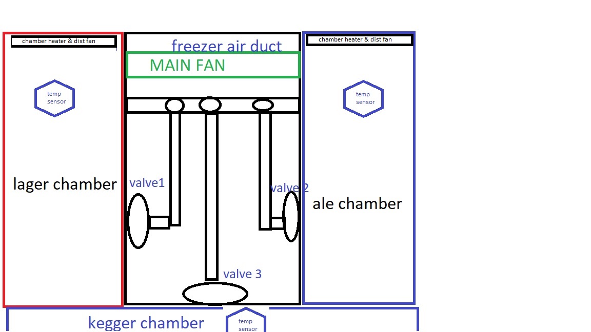
Your advise is much appreciated. I have included a raw drawing to explain the physical design (not to scale, the air control is 5" x 12" and the chambers hold 6.5 gal conical's).
air dist_box.jpg
air dist_box.jpg


script

[fermenting_prep]
"FERMHEAT" State = off
"MAINFAN" State = off
"FERMVALVE" State = OFF
"FERMHEAT" Enabled = true
"MAINFAN" Enabled = true
"FERMTOPSEN" Enabled = true
"FERMVALVE" ENABLED = TRUE

[fermenting_loop]
if "FERMTOPSEN" Value < 64 //this temp probe is 3 degrees hotter at top then in center
"FERMHEAT" State = on
else
if "FERMTOPSEN" Value > 66
"FERMHEAT" State = off
endif
endif

if "FERMTOPSEN" Value > 67 // cool down the chamber
"MAINFAN" State = on
"FERMVALVE" State = on
else
if "FERMTOPSEN" Value < 65 // turn off valve and fan
"MAINFAN" State = off
"FERMVALVE" State = off
endif
endif


[keg_loop]
if "BOTTOMKEG" Value > 55 // keep keg chamber at some temp change later to 38
"MAINFAN" State = on
"KEGVALVE" State = on
else
if "bottomkeg" Value < 53 //turn off cold
"kegvalve" State = off

[heater loop] // this is the defrost circuit for the freeze evaporator, heat 15 minutes every 12 hours


reset "HEATER TIMER" // reset the timer (to its default of 0:00:00)
start "HEATER TIMER" // start the timer running


[loop]
wait "HEATER TIMER" Value >= 11:59:59 // wait for 12 HOURS elapse
"FREZHEAT" state = off
"FERMHEAT" State = off
"MAINFAN" State = off
"FERMVALVE" State = off
"FREEZER" State = off
"FREZHEAT" State = on //turns on freezer defrost heater for 15 minutes

wait "HEATER TIMER" Value >= 12:15:00
"FREZHEAT" State = on
reset "HEATER TIMER" // reset the timer (to default of 0:00:00)


endif


sleep 2000
goto fermenting_loop


Happy new year to all!
KDAZ
 
I’d try having one parent script that turns your fan on/off(based on the status of the air valves). Then use different scripts for each zone you want to control that are started by the parent script.
 
Hello all,

I need some advice if you have a minute. I am two weeks into teaching myself brucontrol and ardunio scripting
and my basic language skills from 30 years ago are not enough. I am presently controlling my new build
"Ferminator 3" a fermentor/kegger/freezer all in one quite well, but now I need to add in logic in the scripting
that is more sophisticated that I understand.

I need to add in two important sub-routines.

Let me set the stage. I am controlling 4 zones, 1- freezer, 2- lager chamber, 3-ale chamber & 4-kegger chamber.
I have a air distribution box that has 1 main fan and 3 electric air valves driven based on the temp in each chamber.
Controlling each with a PID is straight forward, but what I ultimately need is to allow each temp sensor to drive the
valve(s) open and close for each chamber and also turn on the main fan. So each chamber individually has valves but all are
serviced from the same fan. So individually I can turn on the valve and fan, but I am having trouble with the logic to make sure that when all three chambers are "off", I have also switched the main fan off. I cant figure out how "NOT" to disable the main fan once temp is hit for chamber 1 if chamber 2 is also on, or not at temp yet. I don't want to disable the fan while it is needed enabled by the other chamber(s) control.

Secondly, I want to replace the manual defrost circuit for the freezer. Right now it goes on for 15 minutes every 12 hours.
I cant seem to get the logic right and debug fails with the following code (below). When the defrost is on, I need to turn off
all devices. I don't want to run the cooling system while I am heating the evaporator to 50+ degrees. Right now I have a manual defrost control that just switches power off to all devices and on to the heater circuit. Everything is being told by BC to do this and that, but there is no 110v to those devices for them to actually carry out their orders. I could easily leave this as is, but seems silly to have all this control and leave in an $11 plastic analog timer.


The code is below, I know its not efficient, but I am learning. This code does not work but it has the framework of what I am trying to do. I have code that does work (when not adding in the fan control and heating circuit) and other than that it has
been running for the last week quite well. I am not asking anyone to write it for me, I need to learn, but this is getting
out of my wheelhouse and after 4 hours of trying and debugging (and a few brews) I need to reach out for help.
Your advise is much appreciated. I have included a raw drawing to explain the physical design (not to scale, the air control is 5" x 12" and the chambers hold 6.5 gal conical's).
View attachment 605145 View attachment 605145


script

[fermenting_prep]
"FERMHEAT" State = off
"MAINFAN" State = off
"FERMVALVE" State = OFF
"FERMHEAT" Enabled = true
"MAINFAN" Enabled = true
"FERMTOPSEN" Enabled = true
"FERMVALVE" ENABLED = TRUE

[fermenting_loop]
if "FERMTOPSEN" Value < 64 //this temp probe is 3 degrees hotter at top then in center
"FERMHEAT" State = on
else
if "FERMTOPSEN" Value > 66
"FERMHEAT" State = off
endif
endif

if "FERMTOPSEN" Value > 67 // cool down the chamber
"MAINFAN" State = on
"FERMVALVE" State = on
else
if "FERMTOPSEN" Value < 65 // turn off valve and fan
"MAINFAN" State = off
"FERMVALVE" State = off
endif
endif


[keg_loop]
if "BOTTOMKEG" Value > 55 // keep keg chamber at some temp change later to 38
"MAINFAN" State = on
"KEGVALVE" State = on
else
if "bottomkeg" Value < 53 //turn off cold
"kegvalve" State = off

[heater loop] // this is the defrost circuit for the freeze evaporator, heat 15 minutes every 12 hours


reset "HEATER TIMER" // reset the timer (to its default of 0:00:00)
start "HEATER TIMER" // start the timer running


[loop]
wait "HEATER TIMER" Value >= 11:59:59 // wait for 12 HOURS elapse
"FREZHEAT" state = off
"FERMHEAT" State = off
"MAINFAN" State = off
"FERMVALVE" State = off
"FREEZER" State = off
"FREZHEAT" State = on //turns on freezer defrost heater for 15 minutes

wait "HEATER TIMER" Value >= 12:15:00
"FREZHEAT" State = on
reset "HEATER TIMER" // reset the timer (to default of 0:00:00)


endif


sleep 2000
goto fermenting_loop

Happy new year to all!
KDAZ

Check all your if statements and make sure that they have an endif (within the same section headings, check post #1663 and #1664) to make it compile. Also I think you have to remove the "else" between the ifs and nest each "if" with an "endif", like this:

Code:
if "FERMTOPSEN" Value < 64     //this temp probe is 3 degrees hotter at top then in center
"FERMHEAT" State = on
endif

if "FERMTOPSEN" Value > 66
"FERMHEAT" State = off
endif


#1 Something like this, if all valves are off then main fan goes off?

Code:
If valve 1 state == off
if valve 2 state == off
if valve 3 state == off
"MAINFAN" State = off
endif
endif
endif

#2 to keep the loop running and to make #1 work you have to get rid of the wait statement. Use if
Code:
if "HEATER TIMER" Value >= 11:59:59
everything off
heater on
endif

if "HEATER TIMER" Value >= 12:15:00
"FREZHEAT" State = off  
reset "HEATER TIMER"
endif
 
Thanks for the help, I think I understand and will change/test the code tonight!

Cheer's and Happy New Year to all!

KDAZ
 
Sure, I use a bunch of flow meters...it makes sense now about your counter issues.. my bad. I was not following.

So in this case, it would be wheatstone bridge out (i2c?) directly or ("slave") arduino I2c to analog?

the flow is load cells > HX711 board > Uno > BC Mega. Not sure how the HX711 board communicates with the Uno, I just hook stuff up and hope it works :) The Uno outputs a PWM signal to the BC Mega.

I also got the DAC thing working, and that flow looks like:
load cells > HX711 > Uno > DAC > BC Mega

The DAC outputs a 0-5VDC signal. I added a couple more posts to my load cell thread with the setup, arduino code, and a chart showing drift over a couple hours of testing:
https://www.homebrewtalk.com/forum/threads/load-cells.653900/#post-8481379

p.d.
 
I used to go through eBay as well then discovered the same Far East vendor at the same pricing on Amazon.

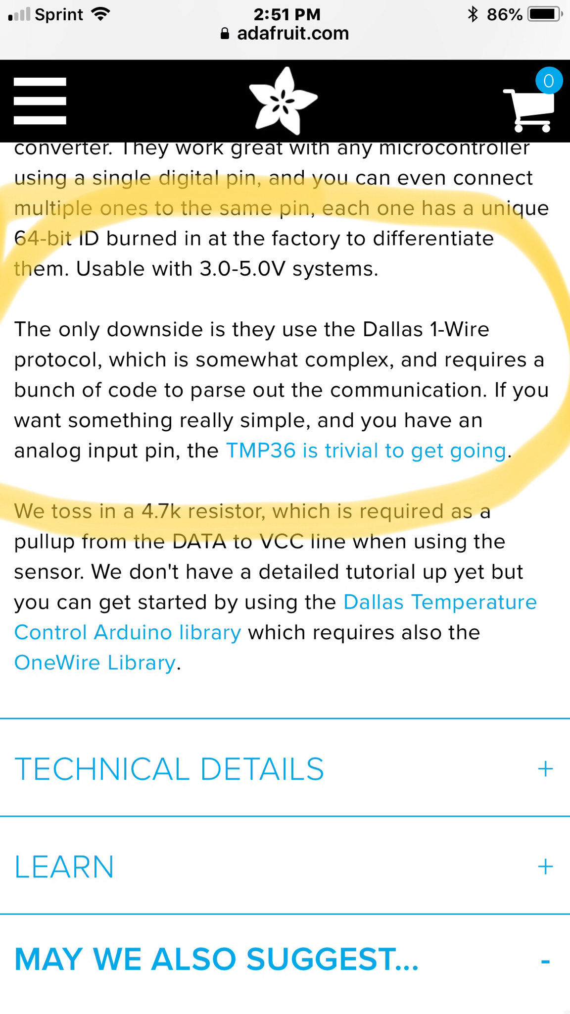
Note to anyone buying one wire probes: makes sure they are NOT DS18B20PAR or -PAR "parasitic mode" models. Over in BrewPi land that's a common mistake as parasitic mode (besides being a bullcrap paradigm) isn't supported...

Cheers!
 
I know some of the vendors are the same but amazon is designed to cater to vendors selling and not consumers, This is why they dont allow searching and sorting by price across multiple categories for something.. I use both but usually only use amazon when I want it quicker and end up paying more for it.
these one wire sensors have been the most susceptible to noise out of all three different types that I use with brucontrol by far.
 
Interesting. Not that there aren't issues with the ds18b20, given the simplicity and relatively low speed of one wire communication I'm surprised to see it compare unfavorably against analog sensors wrt noise sensitivity. I have nearly 3 dozen of them in use or on test platforms and they've always been stable devices - outside of their conversion jitter scope, anyway, and that can be narrowed if programmed for that priority...

Cheers!
 
They are working ok for me at this point but when I still had noise from relays and ground loops the one wire sensors were the worst by far at showing it. my stc1000 2 wire probes never showed it and the rtds sometimes did intermittently... I treid buffering capacitors which helped but didnt truly correct the problem. currently I use them for reporting chiller temp and room temp of the fermenter room.
 
Ok, so I am finally getting ready to start my BruControl build, planned to start over a year ago but life happened.

I plan to start with:

1. Kegerator since one of my stc’s took a dump.

2. BIAB keggle.

I plan to setup 2V with Rims a little later since I have 3 kegs total and the method I use depends on my mood and how much time I have free on the weekends.

Sooooo, my first back and forth...A/C pump with proportional valve orrrr D/C pump with open/close valve?
I know we have both being used here so does one provide better/easier flow control or does it matter either way?

I plan to start with single vessel as stated but expansion will be in the near future once I learn the system.
 
That could be a blue oval/bow tie type debate!

I’d suggest you start with a PWM capable DC pump first. You can use the solar pumps for very low cost as a start then grow from there.

That’s exactly what I was thinking, but want some expert feedback from the BruControl crew.
 
So ran my first production run and about 2 minutes in BAM... power blip in my building... ^&% (^% (&% ^()&^^ %(% (*&

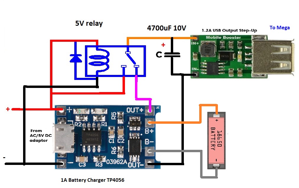
Nothing damaged but my ego and ability to measure the total time of the first run... I am not sure if it got the arduino or if my wifi or ethernet switch, but got me thinking, Is anyone using a capacitor or battery on their mega? I have the adafruit M0 that has the LIPo connector built in and like it...

I saw this from sparkfun but it is retired... building: https://www.sparkfun.com/products/retired/10711 not looking to re-invent the wheel or spend a lot of time
 
@BrunDog--PID question for you. I'm trying to figure out some appropriate PID settings for my RIMS tube/mash, and it seems like the Max Output % setting in the GUI is not working for me. When I set the MaxOutput to anything other than 100%, the element does not fire. When I set the MaxOutput to 100%, the element fires, but I'd like to set the max output to something like 25-35% for mash purposes so that I'm not seeing huge temperature swings in the wort passing over the RIMS element.

Thanks!
 
So ran my first production run and about 2 minutes in BAM... power blip in my building... ^&% (^% (&% ^()&^^ %(% (*&

Nothing damaged but my ego and ability to measure the total time of the first run... I am not sure if it got the arduino or if my wifi or ethernet switch, but got me thinking, Is anyone using a capacitor or battery on their mega? I have the adafruit M0 that has the LIPo connector built in and like it...

I saw this from sparkfun but it is retired... building: https://www.sparkfun.com/products/retired/10711 not looking to re-invent the wheel or spend a lot of time

Some have used DC UPS’s or LiPo batteries. Adafruit sells a power adapter board. It’s referenced somewhere in this thread (way back).
 
@BrunDog--PID question for you. I'm trying to figure out some appropriate PID settings for my RIMS tube/mash, and it seems like the Max Output % setting in the GUI is not working for me. When I set the MaxOutput to anything other than 100%, the element does not fire. When I set the MaxOutput to 100%, the element fires, but I'd like to set the max output to something like 25-35% for mash purposes so that I'm not seeing huge temperature swings in the wort passing over the RIMS element.

Thanks!

That‘s odd. I’ll need to test to confirm.

That said, limiting the output is not really desirable. We have it to provide that safety but appropriate system design and tuning is the best way to ensure performance.

That said, I’ll report back.
 
Some have used DC UPS’s or LiPo batteries. Adafruit sells a power adapter board. It’s referenced somewhere in this thread (way back).

ok, found the Adafruit PowerBoost1000 Charger mentioned back on post 667, would you use the USB cable like adafruit shows (I am connected to BruControl via wifi), or would it work by just connecting the battery and then connecting the gnd and 5v to the mega?
 
That‘s odd. I’ll need to test to confirm.

That said, limiting the output is not really desirable. We have it to provide that safety but appropriate system design and tuning is the best way to ensure performance.

That said, I’ll report back.
OK. I actually designed my system to limit the 5500w RIMS power to 25-35% on mash recirculation based on your recommendation to me earlier in this thread. Obviously if I can get the PID dialed in sufficiently that it does not need a cap on the power output that's fine. Speaking of which, with a 5500w element in my RIMS tube, I should have a setup that is not crazy-dissimilar to yours. Would you mind posting your RIMS tube PID settings as an additional starting point for my testing?

I also still have the power relay from auber that I can install and use to switch the RIMS from 240v to 120v if that's a better approach.

Thanks for all your help.

-Adam
 
ok, found the Adafruit PowerBoost1000 Charger mentioned back on post 667, would you use the USB cable like adafruit shows (I am connected to BruControl via wifi), or would it work by just connecting the battery and then connecting the gnd and 5v to the mega?

I would use it to power the 5V pin.

Alternatively, look at a DC UPS. I have seen users use them here.

Sorry... power failures isn’t something we can control, but this is a very real concern with automation systems as starting into an unknown state is not acceptable.
 
OK, so that means when there is power coming into the Arduino, it charges the battery from the voltage it gets in from the 5V pin, and when the external 12V power to the Arduino is gone, the 5v lead now powers the arduino from the 5v pin? just verifying there is not a separate 'in' and 'out'...
 
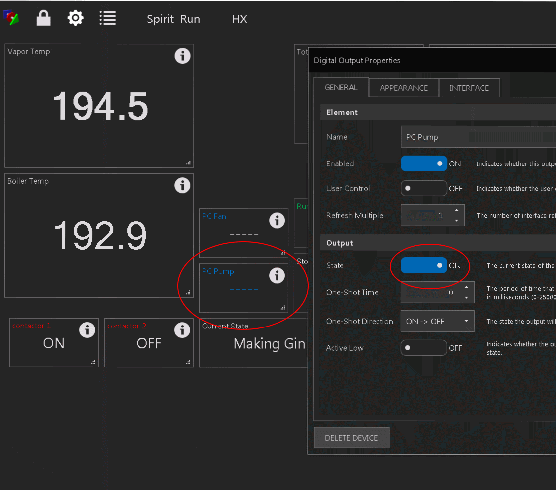
Running my system this morning, I have the following issue, a SonOff Dual Digital output is connected and working, but not displaying the state... I can verify that it is in fact connected in 'settings'-->'interfaces'...... I would reset it, but I do not want to lose my timer data

Edit: I let it run the full cycle and when I restarted it, the problem was cleared.. so disabling and re-enabling does correct it... if it happens again, I will individually try to disable one output and re-enable it.. not sure if there is a log or anything to watch when I do this...

SonOff Dual BruControl issue.png
 
Last edited:
Running my system this morning, I have the following issue, a SonOff Dual Digital output is connected and working, but not displaying the state... I can verify that it is in fact connected in 'settings'-->'interfaces'...... I would reset it, but I do not want to lose my timer data

Edit: I let it run the full cycle and when I restarted it, the problem was cleared.. so disabling and re-enabling does correct it... if it happens again, I will individually try to disable one output and re-enable it.. not sure if there is a log or anything to watch when I do this...

View attachment 606565

+1

I've seen this happen as well on a NodeMCU. It seems like it happens when a script is controlling an output and the script is running while the NodeMCU goes offline and comes back online. Stopping and starting the script works for me. I have also seen it happen on duty cycle outputs controlled by a script. Anyway, on my system at least, the output switches as per the script even if state is not shown in BC.
 
+1

I've seen this happen as well on a NodeMCU. It seems like it happens when a script is controlling an output and the script is running while the NodeMCU goes offline and comes back online.

make perfect sense... the SonOff does go into la-la land for a few seconds once in a while... Murphy got me with the timing being just right...... I will do some tests and collect data on my end before asking for a bug to be looked at...

Edit: it just did it again, the script is controlling it to be on, it is just dashes in the workspace, I can disable and re-enable, and it stays dashes.. The script will not let me turn it off manually, which is understandable.

I did a pause and resume on the the script, and that made them show back up.
 
Last edited:
make perfect sense... the SonOff does go into la-la land for a few seconds once in a while... Murphy got me with the timing being just right...... I will do some tests and collect data on my end before asking for a bug to be looked at...

Edit: it just did it again, the script is controlling it to be on, it is just dashes in the workspace, I can disable and re-enable, and it stays dashes.. The script will not let me turn it off manually, which is understandable.

I did a pause and resume on the the script, and that made them show back up.

Yup it's the same thing we are experiencing. I just got a memory that I had fixed it in the script somehow. Tested and yes its gone but I'm uncertain how I fixed it, maybe it is this small piece at the end of the script, you may give it a try:

if "F1 heat ctrl" Connected != true //checks if interface is offline
"F1 cool" state = false //sets output off if not online
endif
 
Yup it's the same thing we are experiencing. I just got a memory that I had fixed it in the script somehow. Tested and yes its gone but I'm uncertain how I fixed it, maybe it is this small piece at the end of the script, you may give it a try:

I’m using a serial connection and have the exact same problem with all my. devices. Stopping/pausing the script and then resuming/starting fixes it. The Connected property or a sleep command doesn’t seem to help (might be going about it wrong). The only thing so far I found that helps is using a wait statement (for a button press) before enabling devices. I’d like the program/script to load up what’s need and run the program without extra button presses.
 
Back
Top