• Please visit and share your knowledge at our sister communities:
  • If you have not, please join our official Homebrewing Facebook Group!

    Homebrewing Facebook Group

BruControl: Brewery control & automation software

Homebrew Talk

Help Support Homebrew Talk:

This site may earn a commission from merchant affiliate links, including eBay, Amazon, and others.
This looks good seems like you're on track to get it going with BC. I peaked a bit more on the trends you posted earlier e.g this one, I notice that when you increase the setpoint there is a lag before the output starts to increase. The same lag is not there when decreasing setpoint and the output starts to decrease. That might be the same issue I saw when testing which might be related to integral clamping, what do you think @BrunDog ?
I noticed the delay on rise vs on fall also and was a bit flustered!
 
I’ll have to model this but please remember per above, in actual life we are using a unidirectional system. Heating happens actively via the element and cooling happens passively. So they won’t have the same profiles.
 
I think this third point is REALLY solid. There is no doubt in my mind this is where most noise problems come from. Do you have any recommended inline noise filters?

I am also wondering if there are any recommendations for inline noise filters to be used to clean up the power for sensitive equipment.
 
The keys are isolation and suppression. Proper grounding into a STAR pattern matters too to eliminate ground loops.

1. Separate high and low voltage wires. Eliminate loops where possible - they act as antennas.
2. Use shielded wire, with the shield tied to ground at the enclosure side only. Or use twisted wire - this reduces antenna affect.
3. Use solid state or electric switches (relays, e.g. SSRs or MOSFETs) over electromechanical ones (cube relays) where possible. For inductive loads, for DC circuits, use reverse-biased diodes (e.g. 1N4007) and for AC circuits use MOVs (Metal Oxide Varistors) and/or snubbers (R-C network).

For the MOVs, we have tested these with good success. Anything for 120V will likely work though: https://www.digikey.com/product-det...onic-components/ERZ-E14A201/P15585-ND/3694124
Thinking out loud. Surge protectors have MOVs, albeit rated much higher than these like MOVs linked here.

For AC loads like pumps, has anyone tried just plugging in a surge protector between their panel and load?
 
Hmm are you sure the integral minimum is clamped to zero? If I set up a PID with a small gain and medium Ki it integrates nice to 100% on a small error. When I give it a small negative error it moves nice down to zero and back up again if I give it a positive error again. But, if I give it a large negative error it moves rapid from 100% to zero, naturally, but if I then from there gives it the same small positive error it takes forever before to output starts to rise from zero, indicating that the integral did not stop at zero? I played with the max integral setting while doing this and to me it seems like the integral is clamped to the negative value of the max integral? I have tested on the Feather and Sonoff maybe its firmware related just to them? I agree with you for a brewery controller the integral should be clamped to zero not negative max.

Ok, verified this. And you were correct. Somewhere in testing, we must have flipped the switch to allow clamping at negative max rather than zero. So now the call... what do we do? For brewing and unidirectional heating or cooling, negative integration doesn't make sense. But in the application above where a valve is being used to control flow, it should be allowed. Thoughts?
 
Ok, verified this. And you were correct. Somewhere in testing, we must have flipped the switch to allow clamping at negative max rather than zero. So now the call... what do we do? For brewing and unidirectional heating or cooling, negative integration doesn't make sense. But in the application above where a valve is being used to control flow, it should be allowed. Thoughts?

Could you add this as an option to be set, versus hard coded?
 
Ok, verified this. And you were correct. Somewhere in testing, we must have flipped the switch to allow clamping at negative max rather than zero. So now the call... what do we do? For brewing and unidirectional heating or cooling, negative integration doesn't make sense. But in the application above where a valve is being used to control flow, it should be allowed. Thoughts?

Why not have a min integral parameter like the max integral. For unidirectional control (heating only/cooling only) you would want this set to 0, but for bidirectional control like a proportional valve you will want this to be a negative value (probably the negative value of your max integral).
 
Ok, verified this. And you were correct. Somewhere in testing, we must have flipped the switch to allow clamping at negative max rather than zero. So now the call... what do we do? For brewing and unidirectional heating or cooling, negative integration doesn't make sense. But in the application above where a valve is being used to control flow, it should be allowed. Thoughts?

I agree negative integration is not needed for general brewing. As long as we don't use output offset (e.g P output 50% when error is 0) will a negative integrator contribution to the output give any benefit in any case?
 
There is no proportional offset. The integrator serves as that offset. In brewing, once the target is achieved, the integrator will likely be positive and creating the error which drives the output. If the target is exceeded, the integrator will reduce and likewise the total error. Again, for unidirectional system, keeping the minimum integral to zero makes sense, but for bidirectional we should provide the option. We’ll look to add it as a setting.
 
Those sensors are digital. No calibration needed
Thanks for the info, I really appreciate the help as I am new to Bru Control. What I meant was that I eventually want to offset the reading for a nominal value. I have 3 temp probes, top left, middle center and bottom right as I can slightly change the air direction and flow, so I will record, evaluate, adjust the airflow then look at the 3 values after some time and average them, and then leave just one temp probe in long term. I want to be able to offset that reading a few degrees one way or the other so the value I am using in bru control is the closest to the actual temp of the ferm chamber and wort. Does Bru Control allow for an 1 wire temp offset? A better long term solution will be a mounted 1 wire water tight prob into my conical, but Im not there yet. Thanks again for your help, all of us in the brew community thank you and everyone that help us newbies.
 
Yes, they can. And thanks for your more in depth question you just inspired an idea for me with temperature averaging.
 
There it is.. Temp averaging.. I know this was not your direct question.. but it clicked in my head.


Your screen design is amazing, and you have now explained how I can do this as well in my RIMS. I am learning Bru Control and some sketch writing while I change over my Fermerntor fridge hack from Inkbird PID's and relays to BruControl, and I will start adding in the BK and mashing control during the Christmas break. Thanks and have a great one. I will keg my current Funky Budda Floridian Clone on Xmas eve and I will tip one, (ok more than one) to you!
 
Hi Scrooge! Yes, I agree... a little IOT would be nice. But I call this a definite win. The micro is really fast and has lots of memory, which gives us a lot of room to grow. The format matches the MEGA footprint. It won't be PnP due to the 3V architecture, but for many who have minded their current loads it will be a simple swap. I'd like to get it without headers so we can solder in stacking headers to keep the orientation and ultimately make a shield. For the record, the Due does these things, but is getting a little long in the tooth.

For WiFi / Ethernet... a shield on top is easy enough. BT on the other hand... notsomuch. That will be a job for the ESP32.
 
This may go over like a fart in church... but the reality is the MEGA will have a limited lifetime in terms of our expansion. For certain configurations, we are approaching the memory limits of the MEGA. We are optimizing the code to help (v45 will have some dramatic internal changes), but certain functions like WiFi and big I/O capacity erode memory quickly. The MEGA has 8kB of RAM (that's 8192 bytes - about 2 pages of printed text). The micro above has 32x that amount... so you can understand why we are excited about it and other modern micros like the ones in the ESP32 and the Feather M0 lines.

Sub $20 anything is not very likely. Yes we are all very price sensitive, but there is a point where you get what you pay for!
 
I am looking for input on continued issues with the ethernet shield. I got back my controller and W5500 shield I sent to BrunDog for examination and he was able to get it to flash and network setup without trouble. I too was able to do that myself at home once I shifted over to the W.44 firmware and choose the "FR" version. That part works great (W.43 "E" did not, all else being the same as far as I can tell, usb driver and all). I have two controllers to play with and the one shield. Both work and the ethernet shield gets an IP and all is well. The problem is that once I put the screw shield on the controller and then the ethernet shield on top of that, communications to the controller via ethernet fails. The shield powers up and shows a link and activity but no communication to the outside workld. No IP is obtained and it doesn't respond to a ping. Simply remove the screw shield and install the ethernet shield back directly on top of the controller and it works. Rinse and repeat. I have spent considerable time ensuring that all pins are lined up and everything is proper but it simply wont work. I can't see any bad solder on the screw shield. This should be simple stuff but still a problem remains. Any idea how a screw shield could mess with the ethernet shield in this way? Thus far everything works that I have wired up and managed via a serial connection. Am I missing something obvious on pin alignment?
 
Last edited:
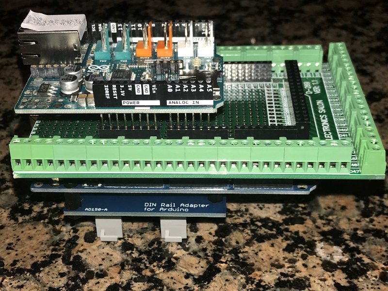
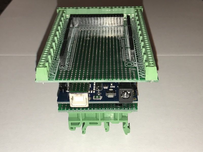
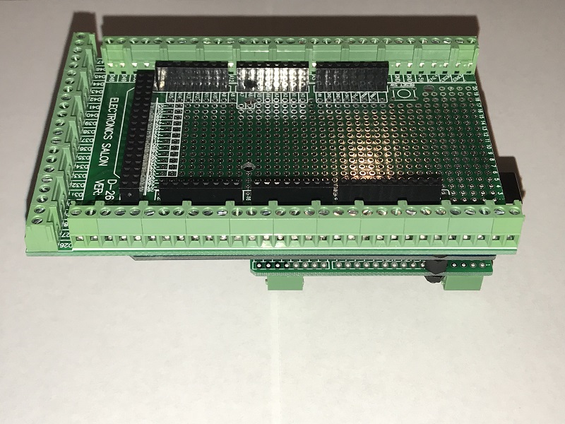
which screwshield? 'board kit' or 'din rail mount'(using order list terminology)

If using the 'board kit', did you add the 2x3 header?
If using Din Rail Mount, are you following what Die_Beerey did?

I bought the "AM-FD:MEGA" option from BrunDog. It is assembled as illustrated in the pictures (albeit that is not the correct ethernet shield in the picture) and yes I have the 2x3 header installed through the screw shield.

Fully Assembled/Tested Arduino MEGA 2560 w/ Screw Shield – This assembly saves the user from having to source multiple parts and assemble/solder the Screw Shield terminals and headers.


Last edited:
Back
Top