OP
OP
You mean with our firmware, or in general?

all great points! rock on! I will look at the ESP32 feather..Hi @clearwaterbrewer... per above, the ESP32 is next.
Yes, the Feather is more expensive, but the platform is reliable and well supported. One consideration: the footprint is baked. The ESP32 has different pinouts and footprint per device, so with the $ savings you get an increased risk that the board you bought doesn't match the format of the last one. Even the "Development" board varies from unit to unit, and we thought if we have to dictate a specific one, then they stop making it, we have just locked you in to a design that is no longer supported. Feather supports add-ons too, so if you wanted to use a basic Feather, then add an Ethernet board... no problem.
Another consideration: you can't (easily) get an external antenna option with ESP32. So if you put it in a metal enclosure, you are kinda screwed. The WROVER based ESP32 has one, but again - the footprints of these are all over the place.
Another consideration... starting small. In designing this, we want to prove a design before going bigger. 16 I/O may not satisfy everyone, but that's OK, we will use this is a simpler and less expensive first step.
We are still testing the ESP32, and have not fully vetted it, so building a board on that adds lots of risk that we get something wrong!


Chiming in with another newb question. I've plugged in multiple 1-wire sensors to the interface but when I add the devices to the workspace it's only reading from a single temp sensor.
Any thoughts on why this is happening?
Yeshave you added the resister ?
Input voltage is 5v, powered from the Arduino. Verified the voltage with a meter yesterday.What is the value of the resistor (check it with a meter). What is the input voltage to the sensors (also check with a meter) and how are these powered? More system details will help us debug with you.

Daisy chaining not such a good idea for more than 2 or three channels... agreed though a single common would be nice.

I guess I misunderstood the wiring. So I'm going to need to wire +24 to each of the C1, C2... terminals?
I assumed I was restricted to 24v outputs. Good to know. But can I actually switch ac as well? Like my ac pumps?That's correct, assuming that the only devices you are trying to control on the relay board are all 24V powered devices.
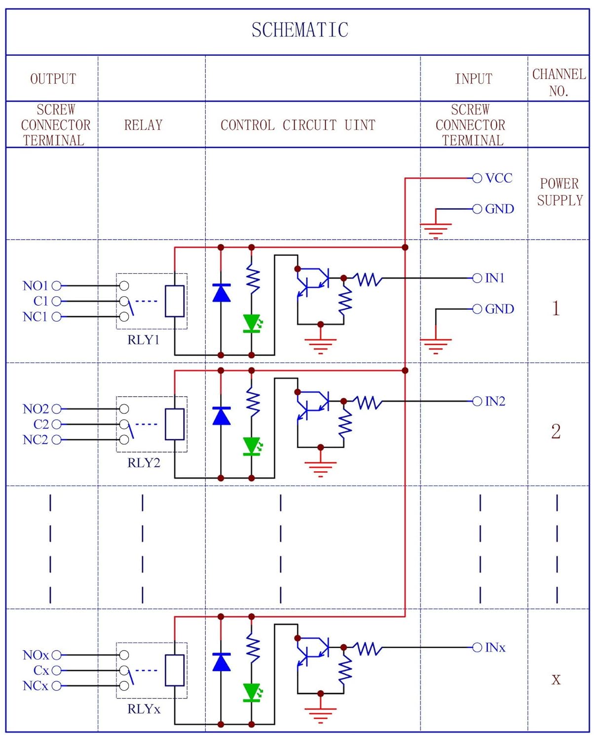
The VCC is just to power the relays (i.e. make the relay itself move). It's an electromagnet that moves the switch from Cx to either NOx or NOx; that electromagnet gets it's power from VCC but it's completely independent of the load the relay is switching.
The reason these boards don't have a single common is that it allows you to drive different types of devices off the same board. You can start/stop an 120 V AC pump on one, a motorized 24 DC valve off another, a 12V DC solenoid on another, and so on. If there were a single common, you'd be locked into having only one type of voltage device to control.
I assumed I was restricted to 24v outputs. Good to know. But can I actually switch ac as well? Like my ac pumps?
That's awesome.Sure can! Each relay's switching side is 100% isolated from any other source. No issue at all with this type of relay board to have each one switching a different type of load (just make sure you're wiring the correct relay to the correct load!)
I've got a 5vdc powered relay board in my panel that switches my pumps on and off (120 vac). Works with no issue.
You do need to pay attention to the maximum ratings of the relays - in this case, I believe that's 10 amps, so don't go trying to switch your heating elements with them!
EDIT: From the Amazon listing: Contact Rating: 125VAC/250VAC 10Amp or 30VDC 5Amp.
Hi,
FYI we uploaded an application note to the website which demonstrates how to build a simple fermentation controller for BruControl, using an off-the-shelf wireless switch, for under $50 (assuming you have most of the tools). This unit is dual-channel, so it can be used to heat & cool a fermentation chamber, run two refrigerators for fermentation & dispensing, run a glycol pump and ball valve for conicals, or do whatever you want with two 120V supplies: http://brucontrol.com/build/resources/
I agree I mentioned this to 2 admins before and then the emails were sent out no earlier than 4:30 pm central now it's 2:30 but still not as fast as it should be
@BrunDog
I know I read about wiring on the proportional valves before, and from what I remember you do not wire the feedback signal wire up on yours? My concern is being able to use the 3-wire XLR connectors.
Arduino's and other micro interfaces typically do not have Analog Out ports (some do, but limited). They have PWM (Pulse Width Modulation) out ports, which is a high frequency, single voltage output. The output voltage is either zero or full, but variation in the output is the percentage of time the output is on. 50% is on for half the cycle and off for the other half. This is like Duty Cycle, but very fast at ~1000 cycles per second.
To convert that PWM signal to analog, a simple Resistor-Capacitor circuit (low pass filter) can be used. The challenge with this is if a proportional valve (or other proportional device like an SSR) requires a bit of current to drive its input signal, the interface PWM output pin and RC circuit combination may not allow it. I have successfully run devices doing this, but using an intermediate board adds safety and likely better control. The AA board converts the PWM signal to analog, then amplifies it to whatever range you need in a proportional signal (for example, 0-10V).
The schematic is fairly straightforward... but we should post up a schematic. I'll do so along with the spec sheet fix - thanks for noting it.


![Craft A Brew - Safale BE-256 Yeast - Fermentis - Belgian Ale Dry Yeast - For Belgian & Strong Ales - Ingredients for Home Brewing - Beer Making Supplies - [3 Pack]](https://m.media-amazon.com/images/I/51bcKEwQmWL._SL500_.jpg)


