• Please visit and share your knowledge at our sister communities:
  • If you have not, please join our official Homebrewing Facebook Group!

    Homebrewing Facebook Group

BruControl: Brewery control & automation software

Homebrew Talk

Help Support Homebrew Talk:

This site may earn a commission from merchant affiliate links, including eBay, Amazon, and others.
Just in case that's what's going on here, powering a Mega 2560 via a long USB cable is bound to fail, and even a short cable can be problematic as the wire gauges vary substantially from manufacturer to manufacturer. I've found 18" USB cables that drop a quarter of a volt just powering an Uno. Bad juju, use the bayonet power input instead...

Cheers!
 
My cable is greater than 6ft maybe 10ft, it seems to still work for communication with the mega on my dining room table. In the control box might be another story though... I plan to power the mega with a 12v power supply and communicate with the mentioned cable. I’m crossing my fingers that it works.

SNANSHI Printer Cable 15... https://www.amazon.com/dp/B01HEXBUYK/?tag=skimlinks_replacement-20

1 ft Panel Mount USB Cable B... https://www.amazon.com/dp/B002M8VBIS/?tag=skimlinks_replacement-20
 
Last edited by a moderator:
Ive used them with 6ft cables, but just an fyi if you go longer than that you want a heavier shielded cable and the cables with the powered repeater/booster built in are best. My employer learned this the hard way with one of the large commercial printers I service where we had too retrograde an updated cable into place due to errors and electrical noise.
 
I didn't have any issues with a 16ft extenstion, then to a 4 port usb hub, then a 10ft (x2 for 2 megas) to the final destination. The computer was in the other room.
 
I didn't have any issues with a 16ft extenstion, then to a 4 port usb hub, then a 10ft (x2 for 2 megas) to the final destination. The computer was in the other room.
@Die_Beerery, any specific brand of cable that you used? Did they have ferrite chokes or anything fancy like that? What about your MEGAs: do they both use the standard arduino usb driver or the "generic" usb driver?

Thanks for any input you can provide.

-Adam

P.S. Off-topic to this thread, but do you have a favorite Festbier recipe? I had Paulaner Wiesn at an Oktoberfest event here in Chicago this weekend and it took me right back to the Theresienwiese. I want a Festbier to be one of the first beers I brew on my new system.
 
My cable is greater than 6ft maybe 10ft, it seems to still work for communication with the mega on my dining room table. In the control box might be another story though... I plan to power the mega with a 12v power supply and communicate with the mentioned cable. I’m crossing my fingers that it works.

SNANSHI Printer Cable 15... https://www.amazon.com/dp/B01HEXBUYK/?tag=skimlinks_replacement-20

1 ft Panel Mount USB Cable B... https://www.amazon.com/dp/B002M8VBIS/?tag=skimlinks_replacement-20
Thanks swimIan. I also have that panel mount cable; I can give that brand of cable a try as well.
 
Last edited by a moderator:
It’s of course a personal choice, but a 2 vessel allows for legit lautering for clear wort, fly or batch sparging, and no need to lift the grain out via bag of basket. You could do back to back if needed as well and it’s a pathway to LODO if desired.
I have a single eBIAB rig now... wondering how a 2 V system works? just curious...
 
@Die_Beerery, any specific brand of cable that you used? Did they have ferrite chokes or anything fancy like that? What about your MEGAs: do they both use the standard arduino usb driver or the "generic" usb driver?

Thanks for any input you can provide.

-Adam

P.S. Off-topic to this thread, but do you have a favorite Festbier recipe? I had Paulaner Wiesn at an Oktoberfest event here in Chicago this weekend and it took me right back to the Theresienwiese. I want a Festbier to be one of the first beers I brew on my new system.


Nope just amazon specials. They use standard drivers.

Paulaner wiesn is just 70%pils and 30% light Munich with 24ibus @ 60. The recipe is nothing, the devil is in the details ;)
 
Just in case that's what's going on here, powering a Mega 2560 via a long USB cable is bound to fail, and even a short cable can be problematic as the wire gauges vary substantially from manufacturer to manufacturer. I've found 18" USB cables that drop a quarter of a volt just powering an Uno. Bad juju, use the bayonet power input instead...

Cheers!
Thanks day_trippr. Powering via 12V in through the VIN pin, so that shouldn't be the problem.
 
Are people typically using flowmeters to determine kettle volume? The BruControl website lists a snazzy looking pressure sensor. Not cheap, but seems like a good solution although a bit pricey. Just wondering what people's thoughts are and if anyone is using it.

If I did use it I imagine I'd use it in the side-mounted configuration.
 
Flowmeters aren’t a great way to determine volume as they have some inaccuracies. If you can control the flow rate so it is consistent, then the FM can be calibrated to be fairly repeatable, so this could be done. On my rig, I use the FM to determine total sparge volume during fly sparge, but admittedly it doesn’t matter if it is off because after sparging the continued draining takes place, so more or less water on top of the grain matters little.
 
Flowmeters aren’t a great way to determine volume as they have some inaccuracies. If you can control the flow rate so it is consistent, then the FM can be calibrated to be fairly repeatable, so this could be done. On my rig, I use the FM to determine total sparge volume during fly sparge, but admittedly it doesn’t matter if it is off because after sparging the continued draining takes place, so more or less water on top of the grain matters little.
So do you use the pressure sensor for kettle volume? On both kettles?

On your proportional valves, do they just go to a predetermined position or do they get feedback?

And if I'm asking answered questions I'm sorry. I'm still doing a lot of reading but as I sketch out things I run into these questions and I can be a little obsessive.
 
I personally use pressure sensors in both my vessels. It depends on what you want to measure. I measure strike water, detect sticking mash, and use the level for electronic auto-sparging in the MLT. In the BK, I measure the fill amount, calculate the boil-off rate, and use it to determine when to stop draining into the fermenter.

I have proportional valves at the exit of both pumps. The mash one controls the flow through the mash, on-demand sparge water heating, and the other controls auto-sparge MLT draining and chiller temp control when transferring into the fermenter. The flowmeter heading into the RIMS tube controls sparge rate and amount. It also acts as a safety, halting the RIMS power in case the flow stops.

These sensors and other can be added or not, depending on what you want to measure.
 
I run ~15 pressure sensors (some liquid and some actual pressure) and 5 or so flows. Since I pressurize my vessels at certain points the liquid pressure sensors don’t work. So i rely on a constant flow rate(proportionals) and the flows during that.
 
I run ~15 pressure sensors (some liquid and some actual pressure) and 5 or so flows. Since I pressurize my vessels at certain points the liquid pressure sensors don’t work. So i rely on a constant flow rate(proportionals) and the flows during that.
Damn, 15 pressure sensors?
 
I personally use pressure sensors in both my vessels. It depends on what you want to measure. I measure strike water, detect sticking mash, and use the level for electronic auto-sparging in the MLT. In the BK, I measure the fill amount, calculate the boil-off rate, and use it to determine when to stop draining into the fermenter.

I have proportional valves at the exit of both pumps. The mash one controls the flow through the mash, on-demand sparge water heating, and the other controls auto-sparge MLT draining and chiller temp control when transferring into the fermenter. The flowmeter heading into the RIMS tube controls sparge rate and amount. It also acts as a safety, halting the RIMS power in case the flow stops.

These sensors and other can be added or not, depending on what you want to measure.

I'm looking for a solution to determine how full each vessel is primarily to tell the system when to stop filling, specifically for filling strike water and then when to stop filling the boil kettle once I've reached my desired pre-boil volume. It will change from batch to batch, so a permanently mounted float switch isn't right for me.

I imagine I'll also want flow meters for fly sparging, which will control the proportional valves, and as you mention as an added safety measure for the RIMS tube.

One downside I can imagine with side mounting the pressure sensor is that it will not tell me when my vessel is truly empty, so I can't simply stop draining the boil kettle based on that unless I'm okay with a significant amount of wort left behind, which I'm not.

I suppose I could have a flowmeter from the boil kettle drain and the fermenter and stop pumping and close valves once flow drops, indicating the BK is empty?
 
There are several ways to determine liquid levels in kettles in a practical way. For binary “at” level, you can use mechanical float or optical switches. Mounted to the kettle doesn’t make much sense to me, so mounting on a steel rod or something you can adjust them up and down. Obviously anything that goes under liquid needs to be able to handle it. Alternatively, if you have a sight glass, you can use optical sight gauge sensors. These can slide up and down to detect any particular level in advance.

Hydrostatic pressure sensors are a great way to detect infinite positions. There are some high-end units like we offer that are sanitary mount and can handle high temps, but a simple pressure sensor which measures pressure via an air gap will work well very inexpensively as well.

Some have used load cells with success but I suspect these are more trouble that it is worth. I would like to see an e-tape that is long enough but they don’t exist yet. I think anything that has to “see” into the kettle like ultrasound or laser is also difficult to set up.
 
The ones you sell look very nice (a plus for me) and seem like they will give me the kind of functionality I want without too much additional hassle. Since I'll be adopting some LODO techniques as I build this new system out I don't want something that can't be used without the lid on.

I'm about to completely build a new brew system. Pretty much nothing I have now is going to be incorporated into the new system, largely because I'm selling most of it.

But I'll be getting custom 30 gallon kettles from Spike Brewing and two of their CF15 conicals.

This is going to be a huge project for me and I'll likely start buying stuff in the next week or two.

@BrunDog or anyone else, do you have a suggestion on a Windows tablet to run BruControl on? I don't imagine the program is too demanding so I'll probably just go with something relatively inexpensive that has the biggest screen for the money.
 
EDIT— sorry that message got posted twice. I haven’t yet tried the second cable with anything other than the MEGA, and I already sent the first one back. I’ll do a quick check to make sure the cable seems otherwise fine.

Another piece of info—I got one of the MEGAs with the generic usb chip. Any chance that chip is somehow more sensitive to errors or something?

What’s the longest cable you’ve used BrunDog? 3 ft? 6?
I'm sure everyone has been waiting with bated breath to know the outcome of my troubleshooting, so here it is. It was the MEGA. Maybe it was the USB chip, or maybe it was from being knocked around during bench testing or in my toolbox waiting for the build. In any case, I procured a $15 MEGA from Amazon with the atmel chip and all is now good. 6 foot and 10 foot USB cables both work great.
 
I ordered a MEGA and I'm looking for guidance about relays (I don't know much about this). In the order list on the BC website, it appears the active low boards are much cheaper than the active high boards. Why is that? Are there any reasons I should not go with an active low relay? I think I understand the software can handle either - is that the case?

The relays will power motorized and solenoid valves, pumps, etc.

Thanks.
 
Closer...

IMG_4981.JPG
 
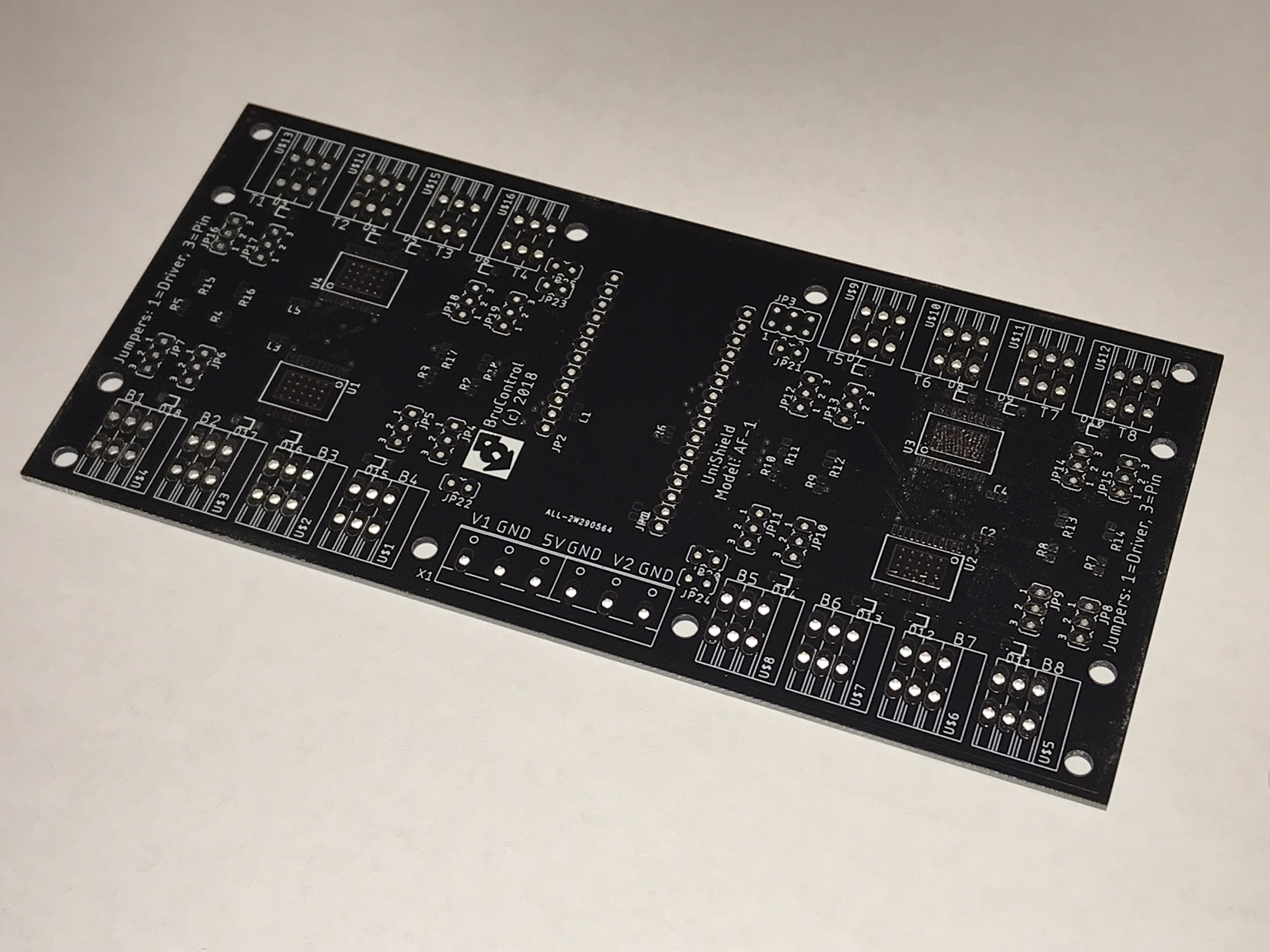
T1-T8 and B1-B8 I guess one could hope for 'T' meaning 8 RTD inputs, but with all 16 looking identical, it could be a christmas lighting board for BruControl for all this EE knows! maybe @passedpawn can tell us...

Bottom/Top.

U1-U4 are likely relay drivers. Looks like the heatsink pad has a matrix of vias under it to shed heat, so maybe he used motor drivers to drive the relay coils. B/T footprints are probably connectors since they don't look like common relay footprints. There's a little diode footprint next to each one to clamp negative inductive spikes when the relay is released. Maybe motor drivers, but only DC brushed since everything else requires current control and I don't see that. My guesses.
 
You guys are too good!!

This is indeed a Feather based driver board, allowing for direct connection of relays, pumps, etc. 16 universal I/O channels, up to 5A per channel. Board is split in half so you can drive outputs at two different voltages, ranges 5V to 24V. Each interface pin will have three terminals provided, managed by jumpers: direct (to interface pin, such as for inputs), driven (high current output or PWM), and ground (for easy wiring). This board fits in a DIN rail carrier for easy mounting. It will have an add-on power board to also provide terminals for 5V and higher voltage for easier wiring. The goal of all these terminals is to allow a builder to avoid needing lots of DIN rail terminal blocks.

@passedpawn spotted some key items: yes, the vias are there to distribute heat, B and T are Bottom/Top respectively, and the footprints are spring terminal connectors. The diode is indeed a flyback diode, even though the drivers contain internal ones.

We went with high side (active high design) drivers, not motor drivers. We had plans to use motor drivers, but at the end of the day, you have to decide a default start-up mode, which would have been low, so it didn’t make much sense to use them since active-low devices would be on during start-up (the difference is active-high only versus both active-high and active-low configurable). Motor drivers also take up more space per channel and are twice the price - and when you multiply out the number of I/O we are looking for, it’s a big difference.

We will be soldering a few up then testing them. We’ll offer these but realize that the I/O is limited for bigger control systems. The next iteration will probably be based on the the ESP32, which will provide more I/O. We want to get to MEGA numbers of I/O, so will probably make a MEGA or DUE footprint model. The challenge with these is we want to avoid proprietary microcontrollers, but we would really prefer models with stacking headers instead of the current model which only has female headers on the top side (requires mounting underneath, which we frankly don’t like).

We hope a design like this, while a bit more expensive for parts, will facilitate a smaller enclosure that is much easier to wire. More to come soon!
 
Last edited:
You guys are too good!!

This is indeed a Feather based driver board, allowing for direct connection of relays, pumps, etc. 16 universal I/O channels, up to 5A per channel. Board is split in half so you can drive outputs at two different voltages, ranges 5V to 24V. Each interface pin will have three terminals provided, managed by jumpers: direct (to interface pin, such as for inputs), driven (high current output or PWM), and ground (for easy wiring). This board fits in a DIN rail carrier for easy mounting. It will have an add-on power board to also provide terminals for 5V and higher voltage for easier wiring. The goal of all these terminals is to allow a builder to avoid needing lots of DIN rail terminal blocks.

@passedpawn spotted some key items: yes, the vias are there to distribute heat, B and T are Bottom/Top respectively, and the footprints are spring terminal connectors. The diode is indeed a flyback diode, even though the drivers contain internal ones.

We went with high side (active high design) drivers, not motor drivers. We had plans to use motor drivers, but at the end of the day, you have to decide a default start-up mode, which would have been low, so it didn’t make much sense to use them since active-low devices would be on during start-up (the difference is active-high only versus both active-high and active-low configurable). Motor drivers also take up more space per channel and are twice the price - and when you multiply out the number of I/O we are looking for, it’s a big difference.

We will be soldering a few up then testing them. We’ll offer these but realize that the I/O is limited for bigger control systems. The next iteration will probably be based on the the ESP32, which will provide more I/O. We want to get to MEGA numbers of I/O, so will probably make a MEGA or DUE footprint model. The challenge with these is we want to avoid proprietary microcontrollers, but we would really prefer models with stacking headers instead of the current model which only has female headers on the top side (requires mounting underneath, which we frankly don’t like).

We hope a design like this, while a bit more expensive for parts, will facilitate a smaller enclosure that is much easier to wire. More to come soon!

Not sure why you're IO limited. Use SPI or I2C I/O expander chips and you can have as much as you like. That's assuming whatever a "feather" is has one of those busses.
 
They do... but I/O expansion is typically I or O, but not both. The interface I/O is very flexible using native pins - we lose that opportunity with expanders.

Any reason for a feather instead of ESP32? To get native wifi you have to use a $40 Feather M0, but a $10 ESP32 has it native..

Any consideration for rtd?
 
Hi @clearwaterbrewer... per above, the ESP32 is next.

Yes, the Feather is more expensive, but the platform is reliable and well supported. One consideration: the footprint is baked. The ESP32 has different pinouts and footprint per device, so with the $ savings you get an increased risk that the board you bought doesn't match the format of the last one. Even the "Development" board varies from unit to unit, and we thought if we have to dictate a specific one, then they stop making it, we have just locked you in to a design that is no longer supported. Feather supports add-ons too, so if you wanted to use a basic Feather, then add an Ethernet board... no problem.

Another consideration: you can't (easily) get an external antenna option with ESP32. So if you put it in a metal enclosure, you are kinda screwed. The WROVER based ESP32 has one, but again - the footprints of these are all over the place.

Another consideration... starting small. In designing this, we want to prove a design before going bigger. 16 I/O may not satisfy everyone, but that's OK, we will use this is a simpler and less expensive first step.

We are still testing the ESP32, and have not fully vetted it, so building a board on that adds lots of risk that we get something wrong!
 
Back
Top