BruControl: Brewery control & automation software

Homebrew Talk - Beer, Wine, Mead, & Cider Brewing Discussion Forum

Help Support Homebrew Talk - Beer, Wine, Mead, & Cider Brewing Discussion Forum:

This site may earn a commission from merchant affiliate links, including eBay, Amazon, and others.
Working on sourcing some plug and play sensors for liquid level (volume) measurement. Taken a couple of iterations but I think these are going to fit the bill.

Testing these on my personal rig. First added a tri-clamp solder-on flange courtesy of BrewHardware.com.
IMG_4238.jpg


Bottom mounted on this kettle but side mount could be accomplished too - anything below the sensor can’t be measured of course.
IMG_4242.jpg


Inside view. Please ignore the stray tooling marks... had an issue trying to cut out the previous soldered-on coupling! Note these will be very easy to clean after - just a little sponge to draw out the extra liquid sitting inside the flange.
IMG_4244.jpg


Initial performance seems good. A bit of upward creep when heating, but nothing that will intro any significant error. Stay tuned!!
 
So I dont know if anyone else has experienced this yet but I'm experiencing voltage spikes from the 240v coils on my element contactors or the contacts themselves which SOMETIMES cause my RTD temp reading to drop out momentarily, These happen more often when deactivating a set of contactors (I have multiple groups of contactors tied together to control up to 4 elements for each kettle and the rims contactor). After googling my symptoms I have found its a fairly common issue thats usually cured with Snubber capacitors for arch quench or MOV placed across the contacts absorb the voltage spike and extend the life of the relay contacts.. I have ordered some and my fingers are crossed they will resolve the issue. I have also addressed the grounding of everything to prevent ground loops which can also cause this interference. a couple times the effect was bad enough to cause the arduino to lose connection with brucontrol and other times theres no effect at all which is strange. when It does happen I can see a faint flicker of all the leds on the arduino relay board which controls the contacts for the main contactor coils.
Turning the blichmann Riptide pump on and off has even caused this problem though through a different isolated relay board, though not as often during testing. I have tried both high level and low level triggering on the relay boards and it makes no difference. I have also tried powering everything off of the usb port and 5v with a 5v relay board as well as powering it off of the 12v meanwell din rail supply and a 12v relay board

Some people have reported other devices like fans causing this as well so I felt it something worth sharing if anyone comes across this issue.
 
Last edited:
Working on sourcing some plug and play sensors for liquid level (volume) measurement. Taken a couple of iterations but I think these are going to fit the bill.

Testing these on my personal rig. First added a tri-clamp solder-on flange courtesy of BrewHardware.com.
View attachment 576612

Bottom mounted on this kettle but side mount could be accomplished too - anything below the sensor can’t be measured of course.
View attachment 576613

Inside view. Please ignore the stray tooling marks... had an issue trying to cut out the previous soldered-on coupling! Note these will be very easy to clean after - just a little sponge to draw out the extra liquid sitting inside the flange.
View attachment 576614

Initial performance seems good. A bit of upward creep when heating, but nothing that will intro any significant error. Stay tuned!!
Who is your supplier if you don't mind me asking? For the volume sensors.
 
So I dont know if anyone else has experienced this yet but I'm experiencing voltage spikes from the 240v coils on my element contactors or the contacts themselves which SOMETIMES cause my RTD temp reading to drop out momentarily, These happen more often when deactivating a set of contactors (I have multiple groups of contactors tied together to control up to 4 elements for each kettle and the rims contactor). After googling my symptoms I have found its a fairly common issue thats usually cured with Snubber capacitors for arch quench or MOV placed across the contacts absorb the voltage spike and extend the life of the relay contacts.. I have ordered some and my fingers are crossed they will resolve the issue. I have also addressed the grounding of everything to prevent ground loops which can also cause this interference. a couple times the effect was bad enough to cause the arduino to lose connection with brucontrol and other times theres no effect at all which is strange. when It does happen I can see a faint flicker of all the leds on the arduino relay board which controls the contacts for the main contactor coils.
Turning the blichmann Riptide pump on and off has even caused this problem though through a different isolated relay board, though not as often during testing. I have tried both high level and low level triggering on the relay boards and it makes no difference. I have also tried powering everything off of the usb port and 5v with a 5v relay board as well as powering it off of the 12v meanwell din rail supply and a 12v relay board

Some people have reported other devices like fans causing this as well so I felt it something worth sharing if anyone comes across this issue.

This does seem to be a problem that has popped up on a few builds. I haven’t experienced it personally but will collaborate with anyone to help figure out he source.

Does this happen when the downstream device (eg pump) is not connected? In the case of the riptide, does it happen with the switch on the pump turned off but power supplied to it via the relay?
 
Working on sourcing some plug and play sensors for liquid level (volume) measurement. Taken a couple of iterations but I think these are going to fit the bill.

Testing these on my personal rig. First added a tri-clamp solder-on flange courtesy of BrewHardware.com.
View attachment 576612

Bottom mounted on this kettle but side mount could be accomplished too - anything below the sensor can’t be measured of course.
View attachment 576613

Inside view. Please ignore the stray tooling marks... had an issue trying to cut out the previous soldered-on coupling! Note these will be very easy to clean after - just a little sponge to draw out the extra liquid sitting inside the flange.
View attachment 576614

Initial performance seems good. A bit of upward creep when heating, but nothing that will intro any significant error. Stay tuned!!

What are the overall dimensions of the sensor and the triclamp portion? How much space would one need under their Vessel to use it?
 
What are the overall dimensions of the sensor and the triclamp portion? How much space would one need under their Vessel to use it?

The tri-clamp is 1.5” so that’s a standard 1.984” flange. The length is about 4” but I will need to report back exact dimensions. These sensors have a radiator section to dissipate heat from boiling level temperatures, so that adds some length. Obviously, the clearance needed below a kettle would be the sensor length plus whatever length your TC flange has.
 
This does seem to be a problem that has popped up on a few builds. I haven’t experienced it personally but will collaborate with anyone to help figure out he source.

Does this happen when the downstream device (eg pump) is not connected? In the case of the riptide, does it happen with the switch on the pump turned off but power supplied to it via the relay?
Im not sure about the riptide but it does happen when My element contactors turn on and off even when the breakers are all off that they feed so I think it may be the coil itself. I picked up some of these
https://www.ebay.com/itm/MOV-V320LA40-V320LA40B-320-Volt-Littlefuse-Varistor-See-Data-Sheet-Quantity-of-5/321084946599?ssPageName=STRK:MEBIDX:IT&_trksid=p2057872.m2749.l2649
as well as arch suppressors to try.
 
BrunDog how far apart are the mounting hole on your Model RP-3: Assembled board? I have a few extra parts and would like to use them to mount the board.
 
Hi HBT,
Many of us implement Voltage/Current meters as a matter of course to monitor AC line voltage and current use. We’ve received several inquiries about voltage/amps measurements, and we have always known it relatively easy to do with a custom circuit, but due to the gentle prodding of @GParkins, I put some energy to identifying an off-the-shelf sensor. For current anyway... voltage is next.

. . .

Now my current will be constantly displayed on my brewing screen - psyched! As I said, voltage is next. Then we can compute power usage, cost, etc. from that data as desired!
Hi @BrunDog-

I grabbed the CR Magnetics current meter from amazon, I'm curious if you've yet identified a similar device to display the voltage to the main input in BruControl.

Thanks!
-Adam
 
Last edited by a moderator:
This does seem to be a problem that has popped up on a few builds. I haven’t experienced it personally but will collaborate with anyone to help figure out he source.

Does this happen when the downstream device (eg pump) is not connected? In the case of the riptide, does it happen with the switch on the pump turned off but power supplied to it via the relay?
Ok so I made some progress... I purchased and add these https://www.auberins.com/index.php?main_page=product_info&products_id=238
across the relays on the arduino relay board which controls power to my contactors, and it seems to have eliminated the voltage spikes. During testing everything was great for a while until after about 20 mins when the temp readings started intermittently dropping momentarily to -412. there was no switching of contactors during this after the initial activation of them to test the hlt and rims heaters. I noticed this temp dropout seem to coincide with the pid switching the 4 ssrs on and off. Then all of a sudden all my temp readouts went to -412.

Upon troubleshooting I found the mega was VERY hot near the voltage regulator area. I let it cool but only one of the RTD readouts came back, until I reloaded the firmware to the mega which restored everything? The only things powered off of my mega which is being powered by a meanwell 12v powersupply are the 2 cr magnetics current meters, the 4 rtds in the brucontrol interface board and the Berme SSR's (four of them controlling 4 elements all in the HLT at the time) I noticed the leds on the ssrs seem to be very dim. I am going to add a small SSR (https://www.ebay.com/itm/HQ-Manger-AC-Solid-State-Relay-DIN-Module-DIN-Rail-Mount-5A/302707799941?ssPageName=STRK:MEBIDX:IT&_trksid=p2057872.m2749.l2649) to drive all of the other ssrs in each kettle off of the 24v din rail power supply I have in the panel and has decided to add a 5v din rail power supply to power anything else I can power to remove the load off the arduino. I am sort of at a loss at what could have caused the arduino to overheat here? The mega im using is the sunflower branded version if it makes a difference but I havent heard of any problems with the voltage regulator on it being weak or undersized.

at the time of testing I was only using my 24v td5 pump and it was being powered and controlled with the manual knob. not through brucontrol.
 
CR Magnetics makes some but I find them too pricey. This is about the best I have found given the price, though it is still more than I would like: Loulensy AC Voltage Transducer Voltage Sensor Transmitter Transformer Input 0-250V AC Output 0-5V DC https://www.amazon.com/dp/B01ANV0RFI/?tag=skimlinks_replacement-20
I found this one on ebay, but I am at least a little bit dubious given that the list price for this sensor is a bit more than $100. I bought it and will report back once I get my panel wired up.
 
Last edited by a moderator:
Most meters you will have to move the red probe to the milliamp connector on the meter, and put it inline with either of the wires powering the SSR, (that is, you have to break the circuit an insert the meter. Connecting the meter across the terminals will just blow the fuse in the meter, or burn something up)

This $6 meter from harbor freight will work, sometimes they are free with coupon. This $21 is a better choice, and also takes thremocouples and does capacitors.. You do not have to move the probe connection on the $6 one, but you would set the dial to the 200mA setting in the 4-O'Clock position(7 o'clock on the $21 meter) to measure ~25mA, if it is less than 20, you can use the 20mA setting for more accuracy.

Get in the habit of moving the probe back to the volt-ohm position if so equipped, and moving the dial out of the current range... it is far too easy to pick up the meter and touch it to something to measure voltage and blow the fuse, or possibly the meter..
 
Thanks I actually own many meters including a bunch of flukes and about 5 or 6 of those free ones. I use them all of the time at work but Ive never measured amp draw with them ironically thoug I feel I should have known this.. learn something new every day. Ive used the clamp style for ac current.
The ssrs dont even get power at all now. All of my temp probes have quit but one which comes and goes.(This happened before and then they just started working again after a firmware reload) I removed the snubbers and the relays still switch but it was switching multiple relays at once so I suspect the relay board may have become damaged from the snubbers and damaged my 2 arduinos while troubleshooting. (it was supposedly an optoisolated relay board so not sure how it could have damaged the arduino) other than through the 12v power supply they both share.
I tried reloading software but its had no effect and I have removed everything from the shield and troubleshot everything individually with no luck. Some things work and some dont. When I plug the 12v power into the arduino it gets very hot the backup arduino doesnt but it also is acting the same way. (Ive verified the 12v supply is outputting 12v exactly) I will try another arduino today with the new relay board I installed after removing the snubbers.

I may just replace the contactors with the 24v coil allen bradleys I have now since I already have a 24v supply in the panel and the voltage spikes from the 240v coils is whats caused all my grief in the first place.

Brundog, Is there anything in brucontrol that could be corrupt that could cause this? just seems odd the I have certian ports on 2 arduinos that dont work at this point? I didnt see any errors when reloading firmware and I dont believe theres fuses on the shield.
At this point I may just start another thread rather than derail this one.
 
Last edited:
No, BC cannot corrupt the interface. They communicate via a protocol and there is no permanence to any instructions sent to the interface. My bet is the Arduino was overloaded and cooked. There is no protection (buffer or driver) between the chip and downstream devices so there was likely too high a currrent draw which overloaded the chip. Each output needs be limited to less than 15 mA absolute max, and less if there are multiple together. This is why I requested you measure the SSR current. You can still do that - just jump the SSR DC+ input through the ammeter to a +5V source directly (can be a 5V pin on the MEGA.) It is possible the power regulator on the MEGA is shot also... you can measure the 5V pin to see what is on it.
 
@BrunDog the brucontrol wizard. He helped me late last night to diagnose and fix a relay issue. And just so everyone knows ( they probably do at this point, I am slow) the relays have 3 inputs. The center being common, left being NO, and the right being NC. So when connecting a valve with 3 wires, voltage goes to middle and the open leg left, and closed leg right. This is not the first time he has helped me with stuff at all hours. Can't say thanks enough, and promote him and his endeavors.. He's the man!
 
I was wondering if I could get some help from the scripting gods.. Here is what I have:

Chiller

Temp sensor (Gylcol Reserve Temp)

Valve (Recirc Loop)

Pump (Glycol Pump)

Hysterisis (Glycol Temp Setting)-using compressor


FV1

FV1 Temp sensor (FV1 Beer Temp)

FV1 Hysterisis (FV1 Set Point)-using valve


FV2

FV2 Temp sensor (FV2 Beer Temp)

FV2 Hysterisis (FV2 Set Point)-using valve

(denote actual names)

So basically you would have a loop of using the hysteresis for chiller to maintain the glycol reserve temp. Which means the pump (Glycol Pump) and the valve (Recirc Loop) will need to be on/open.

Next you have FV1 and FV2, they each have independent hysteresis using a valve for each. Using the same pump.

So the process flow would go something like this...

Maintain Hysterisis (Glycol Temp Setting) with pump, Valve (Recirc Loop).

if FV's call for cooling, close Valve (Recirc Loop), maintain FV Hysterisis (FV Set Point). If at temp or below FV Hysterisis (FV Set Point) turns off and Valve (Recirc Loop) opens.

Basically I want the pump on at all times. Then I want BC to pick what valve to open based on temperature needed. If the fermenters are happy the Valve (Recirc Loop), opens to keep the loops cool, and stop stratification in the reserve.

I probably didn't explain it right...
 
Last edited by a moderator:
I was wondering if I could get some help from the scripting gods.. Here is what I have:

Chiller

Temp sensor (Gylcol Reserve Temp)

Valve (Recirc Loop)

Pump (Glycol Pump)

Hysterisis (Glycol Temp Setting)-using compressor


FV1

FV1 Temp sensor (FV1 Beer Temp)

FV1 Hysterisis (FV1 Set Point)-using valve


FV2

FV2 Temp sensor (FV2 Beer Temp)

FV2 Hysterisis (FV2 Set Point)-using valve

(denote actual names)

So basically you would have a loop of using the hysteresis for chiller to maintain the glycol reserve temp. Which means the pump (Glycol Pump) and the valve (Recirc Loop) will need to be on/open.

Next you have FV1 and FV2, they each have independent hysteresis using a valve for each. Using the same pump.

So the process flow would go something like this...

Maintain Hysterisis (Glycol Temp Setting) with pump, Valve (Recirc Loop).

if FV's call for cooling, close Valve (Recirc Loop), maintain FV Hysterisis (FV Set Point). If at temp or below FV Hysterisis (FV Set Point) turns off and Valve (Recirc Loop) opens.

Basically I want the pump on at all times. Then I want BC to pick what valve to open based on temperature needed. If the fermenters are happy the Valve (Recirc Loop), opens to keep the loops cool, and stop stratification in the reserve.

I probably didn't explain it right...

Ya I am confused. Say what types of devices each are with their names and functions.
 
Random question for everyone. I am currently setting up my brucontrol system and was thinking of using Pt1000 sensors (with the proper pt1000 amplifier) however, I haven't seen anyone using these, only the more common Pt100. Is there any reason why I couldn't use Pt1000s?
 
We haven’t tested Pt1000 amplifiers. I would like to tell you the firmware and software are compatible but I can’t guarantee it without verification.

Is there a reason you are contemplating PT1000 over Pt100? I don’t know of any improvement and would think the 100 ohm nominal sensors are more impervious to electrical noise.
 
Ya I am confused. Say what types of devices each are with their names and functions.

Chiller

Temp sensor (Glycol Reserve Temp) one wire sensor in the gylcol reserve tank

Valve (Recirc Loop)- 12v 2 way valve- when open this runs gylcol though the loop past theother FV valves. This keeps the loop cool, and helps with evening of gylcol reserve tank temps. (port 11)

Pump (Glycol Pump)-120v pump, it is the only pump- so it needs to be running in conjuction with any flow/cooling. (port 10)

Hysterisis (Glycol Temp Setting)-using compressor as the actor and temp sensor (Gylcol Reserve Temp) to maintain 25F in the glycol reserve tank. (port 12)

This loop is... pump out from reserve tank------>though valve(Recirc Loop)--->reserve tank in. When the fermenters are in service this loop will run 24/7 This keeps the glycol at 25F using Hysterisis (Glycol Temp Setting), ready to chill the FV's when they call.
FV1 and FV2 valves closed.


FV1

FV1 Temp sensor (FV1 Beer Temp)-one wire sensor in thermowell

FV1 Hysterisis (FV1 Set Point)-using valve 12v 2 way valve ( Port 6)

When FV1 calls for cooling, it will open its valve, close recirc Loop valve. While everything else stays the same ( Pump on, glycol maintaining temp).

When FV1 is at setpoint (using FV1 Hysterisis) it's valve closes, and recirc Loop opens. I guess it can be looked at as a 4 way valve, just diverting the constant flow somewhere at all times.


FV2

FV2 is going to be the exact same as FV1

FV2 Temp sensor (FV2 Beer Temp)-one wire sensor in thermowell

FV2 Hysterisis (FV2 Set Point)-using valve 12v 2 way valve ( Port 9)

(denote actual names)


Now FV1 and FV2 will call at the same times sometimes, which should be no big deal.
 
@augiedoggy I'm seeing similar behavior on both of my enclosures. On the brewstand controller, I occasionally lose WiFi connectivity when a pump fires, especially when an element is on. I also see temp spikes (PT100s) I need to reset the Mega when that happens. The effect of the reset is that configured valves start going back to their default state, but the pumps keep running. Fluid almost always goes places I don't want it to when that happens.

On the ferm controller, I see temp spikes (1-wire sensors) that appear to be correlated to either the circulation pump or the chamber fans turning on. There, the effect is that the spike goes across all temp sensors, and triggers the glycol chiller to cycle on.

@BrunDog sent me to a link where a guy successfully used ferrite chokes to suppress his symptoms.

Maybe you and I should compare notes and see if we can find a common thread to pull on.

I actually saw this on my new glycol controller. But it’s when a relay shuts off. THe controller loses connection until reset.
 
I actually saw this on my new glycol controller. But it’s when a relay shuts off. THe controller loses connection until reset.

@Die_Beerery I'm not 100% sure on the timing of my "events." I may be spiking during shutoff cycles. I'm going to get a handful of the Auber snubbers that @augiedoggy suggested, and hook them across the COM/NC terminals of the relays for the pumps, fans, and the glycol chiller compressor. Here's how I'm going to do it:

io25.gif
 
I assume that L2L VPN(50mS latency) will work for a network connected Arduino... But will USB port redirection in RDP also work for BruControl, even if just for test environment?

I do most of my tinkering at home, on a separate testbed controller mockup, while the PC and system BruContol will control are 15 miles away at the shop, and I don't think I can have 2 instances of BruControl without an extra license.. (It may be a non-issue, but just wondering, I have a couple of the 5500 cards coming from Mouser, at the best price I have seen, $19.90)
 
@Die_Beerery I'm not 100% sure on the timing of my "events." I may be spiking during shutoff cycles. I'm going to get a handful of the Auber snubbers that @augiedoggy suggested, and hook them across the COM/NC terminals of the relays for the pumps, fans, and the glycol chiller compressor. Here's how I'm going to do it:

View attachment 577325
I think you want the scrubber across the coil:
(random image from google: relay coil snubber wiring )

3WJpo.png
 
First... this seems to be a common issue that is popping up... trust we will get some direction to all to remedy it. I have not witnessed it on my personal rig but I am building some test bed equipment for further evaluation. I am also talking to a new hardware partner for guidance... stay tuned.

Btw, with respect to the above snubber, they should be placed across all contacts where AC inductive loads are fed. So technically both @GParkins and @clearwaterbrewer are correct above. But note our relay coils are DC, and the relay boards we use have flyback diodes (DC “snubber” if you will) built in already.
 
@augiedoggy I'm seeing similar behavior on both of my enclosures. On the brewstand controller, I occasionally lose WiFi connectivity when a pump fires, especially when an element is on. I also see temp spikes (PT100s) I need to reset the Mega when that happens. The effect of the reset is that configured valves start going back to their default state, but the pumps keep running. Fluid almost always goes places I don't want it to when that happens.

On the ferm controller, I see temp spikes (1-wire sensors) that appear to be correlated to either the circulation pump or the chamber fans turning on. There, the effect is that the spike goes across all temp sensors, and triggers the glycol chiller to cycle on.

@BrunDog sent me to a link where a guy successfully used ferrite chokes to suppress his symptoms.

Maybe you and I should compare notes and see if we can find a common thread to pull on.
I ordered ferrite cores last week since I came across that thread in my research... I do not have them yet.
Honestly the arch suppressors from auberins worked well to eliminate the noise for the 20 mins or so I was testing. I did not get one flicker on the sensor readouts when switching the relays on and off.

I found one of my ground wires was loose going into my terminal block which was why I had no power to my ssrs.
Today I will be installing the small din rail ssrs to drive my other ssrs as well as a 5v powersupply for things like the pt 100 amplifier board which appear to be somewhat cutting out because of some poor pin socket connections from all the playing around and swapping I was doing.. I hope to get that all sorted out today.
 
Last edited:
I think you want the scrubber across the coil:
(random image from google: relay coil snubber wiring )

3WJpo.png
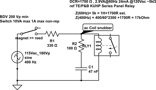
putting arcoss the relay contacts of the relay that powers my coils actually worked I assumed I damaged the relay board with them though when things started acting up but now I wonder if it was the poor ground connection.

I have 3 different types of snubbers, MOVs and varistors I bought though in case I needed to wire some across the actual relay contacts or coil... I'll admit I find this a bit confusing since Ive read so many conflicting opinions on all this. I may move them to the contactor coils since I would think that would be were the issue lies.. I did purchase another relay board I have to swap out as well (also optoisolated)
 
Last edited:
Back
Top