• Please visit and share your knowledge at our sister communities:
  • If you have not, please join our official Homebrewing Facebook Group!

    Homebrewing Facebook Group

BruControl: Brewery control & automation software

Homebrew Talk

Help Support Homebrew Talk:

This site may earn a commission from merchant affiliate links, including eBay, Amazon, and others.
I would think that you want a fairly fast Whirlpooling speed and let it settle. We run uncooled tap water thru the chiller while Whirlpooling for 15 minutes. We let settle for 15 minutes and the Whirlpooling slows down by itself. We do not throttle down the output for Whirlpooling.

We also use a two stage Chiller. By pre cooling during the Whirlpool, we use a second plate chiller that cools the tap water with glycol when transferring to fermenter.

It would be neat to have the proportional valve on the output for the Wort. We use a manual ball valve.

That being said, we can normally use full flow through the Plate Chiller to the fermenter.

Big Hint: Have a BruControl controlled valve on your cooling hose water and have it shut off on a timer. I don't know how many times we forgot to turn off the water!
 
With regards as to which interface to use I would go with the MEGA only because you have more types of ports available to you to use. When I built my main panel my intentions were to incorporate both brewing and fermentation into one single panel. I soon realised I had used a lot more ports than I had originally planned on and thus went to a separate Fermentation/ Instrumentation panel which cut down drastically on stray EMI interferance. I realise your panel build is for fermentation purposes, but my thinking is go bigger than you think because there are always improvements that can be made in future if you have availble ports on the interface.
My fermentation setup employs the use of a glycol chiller and heat tank each temp controlled with STC1000's not controlled via BruControl and the temp in my jacketed conical is regulated using 2 3 way valves (24VDC) and 2 pumps (24VDC) With a small script I can hold fermentation temps at +/- 0.5F of set temp.
 
Last edited:
I would think that you want a fairly fast Whirlpooling speed and let it settle. We run uncooled tap water thru the chiller while Whirlpooling for 15 minutes. We let settle for 15 minutes and the Whirlpooling slows down by itself. We do not throttle down the output for Whirlpooling.

We also use a two stage Chiller. By pre cooling during the Whirlpool, we use a second plate chiller that cools the tap water with glycol when transferring to fermenter.
Interesting, so at flameout you start running the wort through the chiller and back to the whirlpool. Hadn't thought about that.

So your steps are whirlpool/chill and then chill/transport-to-fermenter. My plan was Whirlpool and then chill/transport (hose water) and then chill in fermenter (fridge water). Do you think I would be better served by either of:
  1. Whirlpool/chill (hose water), transport, and then chill in fermenter.
  2. Whirlpool/chill (hose water), chill/transport (hose water again) and then chill in fermenter
I would have to change some of my plumbing to connect the chiller-out back to the whirlpool-in. Both 1 and 2 would require same plumbing adjustments.

I actually spent a little time thinking about it while this post was in draft...... I could accomplish #2 above without having to get any additional auto-valves, but
  • I would lose proportional mash re-circ. I have MT false bottom with wide cross-hatch and I am doing BIAB (3 vessel system, just for ease of cleanup) so thinking that full-bore mash-recirc might be OK. Probably a decent amount of drag from all the HERMS piping to slow it down a little.
  • I would also have to take the sparge output from MT through the chiller (without the cooling on) to the whirlpool-inlet. That is 10' of hose plus the chiller coil rather than 2' of hose. Guessing that would drop temp and mean extra time to get to boil.
Wondering what your thoughts are on that change. Worth it to get the immediate chill during the whirlpool and gain unlimited passes through the chiller rather than one and done before 2nd stage cooling via coil in fermenter?
 
Lots of way to chill... the only thing I will tell you is pre-chilling flush water into a chiller is not efficient. For whirlpooling, if you want to do hop-flavored beers without isomerizing the hop oils, you will need to chill to ~170 deg F first, so chilling into the whirlpool first can be a good strategy. On my personal rig, I run 2 serial chillers inline to the boil loop, and a 3-way valve can direct the wort back to the BK or to the fermenter. I use the first chiller (tap water) to bring the temp down to 170 and hold it for the whirlpool and hopstand. Then single pass to the fermenter using both chillers, with the second using an ice water pool as its chilling source.
 
Thanks for all the replies, which is very much appreciated, and the 3-wire valves certainly helps to get things started.

In terms of interface, I have both Ethernet and Wifi in the Brew Shed, and I have been messing about with both Mega and Feather just for connection purposes and both appear to work ok. Also for info my 1 BBL Unitanks are Jacket / Walled Cooled, and I am unlikely to have any success adding a Tilt due to the thickness of steel in the walls.

The heater pads are similar to the picture, with Mat Dimensions - 250x150mm, Power - 200w, Voltage - 230v, so my calculations indicate <0.9 Amps per Unitank?

The Glycol Cooler similar to the picture is a Vision 21 and the specification indicates that the flow Pump is 80 Watts, and again my calculations indicate <0.4 Amps.


Again any help would be appreciated, and once I have my parts list, I'll draw up a sketch diagram to share with you for comments, before I place the actual orders.

Thanks again for you guidance.


View attachment 772799View attachment 772800

I think the standard relay board will do it for you. Those electromechanical relays included on those boards are rated for 10A @250V, so you should be OK. The chiller will have a high starting current load, but should still be alright.
 
Interesting, so at flameout you ....

So your steps are whirlpool/chill and then chill/transport-to-fermenter. My plan was Whirlpool and then chill/transport (hose water) and then chill in fermenter (fridge water). Do you think I would be better served by either of:
  1. Whirlpool/chill (hose water), transport, and then chill in fermenter.
  2. Whirlpool/chill (hose water), chill/transport (hose water again) and then chill in fermenter
I would have to change some of my plumbing to connect the chiller-out back to the whirlpool-in. Both 1 and 2 would require same plumbing adjustments.

I actually spent a little time thinking about it while this post was in draft...... I could accomplish #2 above without having to get any additional auto-valves, but
  • I would lose proportional mash re-circ. I have MT false bottom with wide cross-hatch and I am doing BIAB (3 vessel system, just for ease of cleanup) so thinking that full-bore mash-recirc might be OK. Probably a decent amount of drag from all the HERMS piping to slow it down a little.
  • I would also have to take the sparge output from MT through the chiller (without the cooling on) to the whirlpool-inlet. That is 10' of hose plus the chiller coil rather than 2' of hose. Guessing that would drop temp and mean extra time to get to boil.
Wondering what your thoughts are on that change. Worth it to get the immediate chill during the whirlpool and gain unlimited passes through the chiller rather than one and done before 2nd stage cooling via coil in fermenter?
We plumbed so that any vessel can go to any vessel thru any port. We have a loop manifold and planned it so we can do that. You can create a small copper recycle tube with a little soldering that is at the top of the vessels (preferred for Whirlpooling) and not use any of the ports on a vessel. In fact, if I was buying vessels again, I would not get any tangential inlets as we made a widget to go over the top and it worked just as good and a lot less $$. You can "tangential" any vessel you have.

Depending on the tap water, we can get down to about 150 or so with just the tap water while whirlpooling. Definitely in the winter but late summer our taps can be up to 85-90.

Using the home made widget allows you to leave your plumping as is for the most part.

We also have a Tee and two manual valves on our pumps. We always have a free port for almost anything.


Pump_Yellow_Rip_Off with Tees.png
 
We plumbed so that any vessel can go to any vessel thru any port. We have a loop manifold and planned it so we can do that.
So, do you have three way valves at each connection point in the loop? Just opening the output and the input with a pump in-between would allow a loop to also flow back to the original output. Seems you would have to not only open an exit from the loop, but also block the continuing loop at that point. Also, I assume you do not fly sparge. Two simultaneous flows would require two loops and then you complicate the network with each access point needing to connect to both loops, but not let the loops flow into each other.....aye aye aye.

Another problem I am thinking about is that because every port is at a static point in the loop and because pumps can't reverse flow direction, how would you get liquid from an access point closer to the pump outflow to travel to a point further from the pump outflow.....I am starting to think that I am incorrectly visualizing this loop. Do you have a post summarizing the loop architecture?

I don't think there is any way I am jumping ship to this model, but it is a really interesting thought exercise. Kind of blowing my mind.

For my config, realized I am going to need another moto-valve in order to get the whirlpool continuous hose chill. Will need a second additional moto-valve if I want to continue to proportionally flow the mash re-circ. Anyone have any thoughts on the importance of controlling mash re-circ speed? Is march pump full-bore for mash re-circ OK if I am BIAB with a very wide slotted screen at the bottom?
You may get a stuck mash if the recirc flow is too high. My last batch I upped my flow from 1 gpm to 2gpm. The flow steadily reduced from 2 to 1.5 over 30mins as the bed compacted. This will depend on a lot of things like your grind, mash composition, vessel and screen, but not having control could lead to issues.
 
Here it is. No three way buy lots of 2 way valves. We can do two 25 gallon batches at the same time and even clean one Brew Kettle while the other is still in use.
Ah yes. Makes sense now that i see each vessel has its own pump so that it is always at the start of the loop it is using. Can also see that you are segmenting two different parts of the loop in order to be able to use two different pumps at the same time. Picture worth a thousand words Very clever. Is that a pro brewer standard or did you work that out on your lonesome?
You may get a stuck mash if the recirc flow is too high. My last batch I upped my flow from 1 gpm to 2gpm. The flow steadily reduced from 2 to 1.5 over 30mins as the bed compacted. This will depend on a lot of things like your grind, mash composition, vessel and screen, but not having control could lead to issues.
Thx @staffordj I am going to leave my Proportional valve at the pump 2 outflow and then also have regular ones after that in serial for the two directions: mash tun re-circ and chiller. That will allow me to use the Proportional for both re-circ and chilling.

I have a manual 3 way that I can stick on the chiller out for now. one way to whirlpool, other way to fermenter. Will need to replace manual 3-way with a tee and two new motos at the chiller output so I can avoid the horror of touching a ball valve. :) I think that will officially max me out on uniflex v2 binary outputs (11)

Cheers for the help.
 
You may get a stuck mash if the recirc flow is too high. My last batch I upped my flow from 1 gpm to 2gpm. The flow steadily reduced from 2 to 1.5 over 30mins as the bed compacted. This will depend on a lot of things like your grind, mash composition, vessel and screen, but not having control could lead to issues.
Rice Hulls! They are magic.
 
"Ah yes. Makes sense now that ... did you work that out on your lonesome?

On my own. I had a disaster on April 16, 2020 as my barn burned down (unrelated to brewing). I got to start over and had been brewing since 2008. We had gone to a hard piped manifold and 5 pumps before. We generally NEVER touch a hose with a couple of exceptions (the hose to the fermenter is sanitized in a recycle).

Years ago I removed a hose and got some very hot Wort on my foot. I ended up at the emergency room about midnight when I went to bed. When I took off my sock, I had some significant blisters. It did not hurt which is a clue. It was only very bad 2nd degree burns. We bought more pumps the next day and hard piped the brewery, No more hose moving.

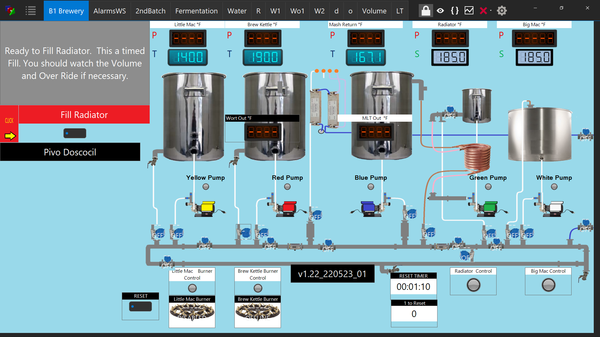
We clean while we are brewing and cycle PBW in the pumps and vessels. The loop is for that purpose. In addition, we use a modified HERMS where we use a counter flow chiller to maintain the Mash Temp. Works like a charm. Since we use distilled water in some of our Lagers, we also use the small Radiator (15 gal) to heat the distilled water for Strike.
 
Is there anyway to do a Universal clean
clear.png
(all the scripts at once) of the Output and Variable panes of the Script Window.

I would like to clean them all prior to running a brew session.

Would really be nice to have a script command to clean both the output and variables of a script.

some thing like:

cleanoutput "my script"
cleanvariable "my script"

I could then add these to my start up routine. That would take care of universal clean as well.
 
Really for troubleshooting (debugging) issues in my scripts. I did something and my scripts get in an endless loop.

On script is causing another script to go backwards and not complete what it is doing. I was cleaning up all my print commands in the scripts when I messed it up. I obviously deleted something, I use the print command to see if a script executes to a point. The is no error thrown as the computer commands are good, just trying to see why it is doing what it is doing. Just be easier to clear the output pane automatically .


In practice, I only look at the output script when writing a new script or section of a script.
 
For anyone needing port 0 on their ESP32 / ESP8266, or Feathers, we updated the FW to accommodate it. Grand Central is *possible*.

We avoided certain ports like these because serial communications are used there, but since we don't need it during network communications, it is possible to use those. We'd like to test the FW further, but if you are in dire need of that port, LMK! The version will be 45P and will be updated shortly. I don't recommend you upgrade if you don't need it.
 
On arduinos, analog ports can be used as digital pins also. With the Brucontrol interface as I understand it, they can only be analog inputs. On the mega or grand central this would add 15 potential digital io pins if you don't need the analogs.
 
Well, I just looked and you may damn be right... The MEGA 2560 Analog Input pins seem to be able to become digital output pins, too. We'll do some testing on it!

Edit: And ya'll gonna really hate if we then convert port 100-115 into 54-69! o_O
 
Last edited:
Been out of the loop for a while, has there been any thought on integrating in an off-the-shelf wireless thermometer system of some sort, such as a bbq or smoker thermometer? I got a new pizza oven and want to monitor/alert temps, and maybe someday control them...
View attachment 769191
Very late and appears to be off-topic, but replying to @clearwaterbrewer question in May:
I built a HeaterMeter years ago for controlling temps on my Costco version of the Big Green Egg

HeaterMeter Hardware v4.3.3, v4.3.4, v4.3.5, v4.3.6

and

HeaterMeter 4.3 Hardware · CapnBry/HeaterMeter Wiki
 
Reading the UM-1 Notes, for heat, it seems best to power a Unishield with just 5v, The internal regulator on a Grand Central will convert that to 3.3 v and the heat is not an issue according to the notes. My interface is inside a barn and it is not A/Ced so I want the less heat generated possible.

All of my transformers, Proportional Controllers, SSRs and Electrical Contractors are in separate boxes.
The only things in the Interface box are the 3 Interfaces, an AA-2, and a TF-4.

I have a 12 vdc 5 amp transformer to power my interfaces. It will power the Grand Central Unishield, A Mega 2560 Unishield and an EtherMega.

I have set the output exactly at 5 v with the little Unishield "VR ADJ" potentiometer.


Is my plan valid?

The Ether Mega is so I can create pseudo Elements (real elements but wired to nothing). I use these to put the same Element on different workspaces. For example, I have the real "Yellow Pump" on my Mega Unishield on my main brewery workspace, and I have a pseudo "Yellow" pump on my Second Batch workspace. I can control the real "Yellow Pump" (via scripting) from either workspace.

I know I can do that with other methods but the interface is not much and all the Elements have the exact same "feel" and properties so they can be an exact match except for their native name.

My Power banks on the Unishields have their own transformers (one for the Grand Central and one for the Mega) as well as a 5 vdc Buck for anything needing 5 volts. Most of the output of the Power banks is for 12 vdc Contactors (there are 8 total). Everything else is minimal or proportional (and off the P Pin).

The 5 vdc Buck is 20 amps so I could also use that to power the interfaces if that would be better. If the 5 vdc buck is a better option, let me know.
 
Last edited:
I'm not sure what you are saying... are you feeding the UniShield with 5V, or setting the VR output to 5V? Our default, and what we suggest, and what I think you are saying, is you feed the US with 12 or 24VDC (likely the same power driving your other DC devices), and keep the VR output to 5V, with the switch VR-->5V. This will power the GC or MEGA interface microcontroller board with 5V, which keeps them very happy. The MEGA will run on that 5V directly and the GC will use its onboard regulator to drop that to 3.3V.
 
Very late and appears to be off-topic, but replying to @clearwaterbrewer question in May:
I built a HeaterMeter years ago for controlling temps on my Costco version of the Big Green Egg

HeaterMeter Hardware v4.3.3, v4.3.4, v4.3.5, v4.3.6

and

HeaterMeter 4.3 Hardware · CapnBry/HeaterMeter Wiki

Nice! Lots of ways to do it. BC can definitely read temps and control a fan. Been meaning to build a quickie, just time burn and I have been lazy on my smoking lately as my BGE tends to hold temp pretty well based on the vent positions.

Unfortunately 1-wire caps out at 255 deg F so these aren't usable. Need to be RTD or thermistor, which needs the extra hardware to integrate. Driving a fan is super easy via a FET or DC:DC SSR, or even standard electromechanical relay.
 
Has anyone tried using this ESP32 + relay board from Lilygo (and with success)? Amazon.com: LILYGO TTGO T-Relay ESP32 Wireless Module DC 5V 4 Groups Relay Development Board 4MB Flash WiFi BLE Remote Switch Control (T-Relay T- U2T Kit) : Electronics

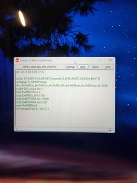
It's incredibly ideal for a BC setup, but it comes with its own USB to TTL programmer that must be used to interact with the ESP32, which is causing me issues when trying to setup WiFi. I can load the BC firmware, seemingly, but when it comes to setup, I can't get Termite to play nice. If I boot the ESP32 regularly, I get the attached image, seemingly showing AP mode (and I see the WiFi signal, not sure what I can do with that, and I have no password). I try entering "%0&15;" (no quotes), but nothing happens.

Test 1: When I press Boot and the U2T button, the ESP32 goes into download mode, but then there's nothing on Termite other than [00][00]. "0&15;" doesn't work either.

In some random chain of events, I did manage to het "0%15;" to trigger, and I entered the WiFi details, but when I rebooted the device, it never appeared on my WiFi.

Test 2: I tried installing BruControl.45O.ESP33.W.bin, then tried 45L to make sure it wasn't a version issue with this board (which I doubted). No difference.

Test 3: BruControl.OutputsTest.ESP32.S.bin works though, so that's a great sign. The four relays light up (two blink), then LED5 blinks, then the cycle repeats consistently.

Test 4: I also connected the board to a 12V source on the input pins incase it was a powering issue. Still nothing appeared.


The chip is ESP32-WROVER-B, if that offers any insight.

Any thoughts here, BC community?
 

Attachments

  • 20220716_140043.jpg
    20220716_140043.jpg
    1.2 MB
Has anyone tried using this ESP32 + relay board from Lilygo (and with success)? Amazon.com: LILYGO TTGO T-Relay ESP32 Wireless Module DC 5V 4 Groups Relay Development Board 4MB Flash WiFi BLE Remote Switch Control (T-Relay T- U2T Kit) : Electronics

It's incredibly ideal for a BC setup, but it comes with its own USB to TTL programmer that must be used to interact with the ESP32, which is causing me issues when trying to setup WiFi. I can load the BC firmware, seemingly, but when it comes to setup, I can't get Termite to play nice. If I boot the ESP32 regularly, I get the attached image, seemingly showing AP mode (and I see the WiFi signal, not sure what I can do with that, and I have no password). I try entering "%0&15;" (no quotes), but nothing happens.

Test 1: When I press Boot and the U2T button, the ESP32 goes into download mode, but then there's nothing on Termite other than [00][00]. "0&15;" doesn't work either.

In some random chain of events, I did manage to het "0%15;" to trigger, and I entered the WiFi details, but when I rebooted the device, it never appeared on my WiFi.

Test 2: I tried installing BruControl.45O.ESP33.W.bin, then tried 45L to make sure it wasn't a version issue with this board (which I doubted). No difference.

Test 3: BruControl.OutputsTest.ESP32.S.bin works though, so that's a great sign. The four relays light up (two blink), then LED5 blinks, then the cycle repeats consistently.

Test 4: I also connected the board to a 12V source on the input pins incase it was a powering issue. Still nothing appeared.


The chip is ESP32-WROVER-B, if that offers any insight.

Any thoughts here, BC community?
As a follow up, I reinstalled 45O, walked away, came back, and then tried the setup routine. It let me enter "0&15%," let me input things, then let me save. I rebooted the device... and it's still not appearing on my WiFi network, but I see its AP in my phone's WiFi list..
 
Back
Top