BruControl: Brewery control & automation software

Homebrew Talk - Beer, Wine, Mead, & Cider Brewing Discussion Forum

Help Support Homebrew Talk - Beer, Wine, Mead, & Cider Brewing Discussion Forum:

This site may earn a commission from merchant affiliate links, including eBay, Amazon, and others.
Depending on the duty cycle, you might get away with appropriately sized contactors. They are typically rated for hundreds of thousands or millions of cycles. [blasphemy ON] You don't really need PID to heat water. Assuming it is mixing well and the lag between it being heated and the temp measured is low, you can easily just use a hysteresis mode and get very stable temps [blasphemy OFF].
 
Ok thanks for the help. What is pulse width modulation and what are you guys using it for?
 
I use PWM with an analog amplifier board to control proportional valves, and I suppose one could use PWM to very precisely control electric heating elements via a phase angle SSR or SSVR. I'm sure there are other uses, but nothing immediately comes to mind.
 
That part is essentially a rapid charger for lithium batteries that provide backup power to the MEGA in case of a power blip or outage.
This guy? https://learn.adafruit.com/adafruit-powerboost-500-shield-rechargeable-battery-pack

https://www.adafruit.com/product/1944

i see the benefit of having power during the blip but what’s the benefit during an outage? Won’t everything else be de energized and the Mega running by itself?

I have the immediate option to bring 5v to supply Mega. Would this be better than the current 12v?
 
Last edited:
This guy? https://learn.adafruit.com/adafruit-powerboost-500-shield-rechargeable-battery-pack i seethe benefit of having power during the blip but what’s the benefit during an outage? Won’t everything else be de energized and the Mega running by itself?

I have the immediate option to bring 5v to supply Mega. Would this be better than the current 12v?

The benefit of keeping power to the controller is that all of your devices, energized or not, are in a known state. This way, when the power does come back on, valves, pumps, heating elements, etc. don't randomly cycle on/off as the controller does not have to reinitialize its I/O.
 
New version with Alias?
MCNBgf5.png
 
i see the benefit of having power during the blip but what’s the benefit during an outage? Won’t everything else be de energized and the Mega running by itself?

I have the immediate option to bring 5v to supply Mega. Would this be better than the current 12v?[/QUOTE]

In my circumstance I tried using a dedicated 5VDC power supply via VIN but was still a no go. Although the disconnects were diminished they still occurred. At that point I decided to go with the 5V 2.5A Switching Power Supply with 20AWG MicroUSB Cable. This directly plugs into the micro USB on the MEGA and eliminates the VIN hookup altogether.

For the PowerBoost module as @RiverCityBrewer mentioned it keeps the devices alive in the last known state before a blip in power. Another added bonus to using the Power Boost board is that it allows me to disconnect the larger USB cable from it and plug into my laptop for updates to BC. It eliminates the screwing around with the micro USB on the MEGA board, possibly damaging it. The power boost is not required if you don't require it. I looked at it as an added benefit for my setup.
Basically the setup is the Power Supply Micro USB cable-Into Power Boost Board-Out of Power Boost Board via large USB to Micro USB adapter cable- Into Micro USB of the MEGA.
Eliminate the battery backup and its a direct connect Micro USB from the power supply into the MEGA.
Edit... This is the one I used https://www.adafruit.com/product/1944 + https://www.adafruit.com/product/1995
 
Last edited:
For example, on my refrigeration interface, it has a battery backup. Should there be a big power failure and my BC running PC not restart (Murphy's law), then the re-started interface will not know what devices should exist and be active... so the refrigeration would not continue. Battery backup prevents this.

That said, we did add the ability to store a "default state" for interfaces, that start up with certain devices active. This doesn't replace a battery backup, which will keep an interface status quo, but it certainly sets it to a known state.
 
We’re nearing completion on our 3 head keg washer. We are using a PLC (Unitronics V350) with touch screen to control ball valves, I wished we would’ve used BC but the build was in motion before I was comfortable with BC or automation in general. Our friend who is helping us with the electrical mentioned to use a PID or a temperature transmitter for the PLC. I like the idea having PLC control heat but don’t like the price tag. Does anyone know a more cost effective way of allowing the PLC to have control over the element?

the transmitter he linked
https://www.automationdirect.com/ad...=FC-T1&categoryId=0&TxnNumber=-1&searchqty=10
 
Last edited:
A lot is going to depend on what PLC you are using? I work with AB/Rockwell gear... I wish I could get a transmitter for $100. Typically you add a 0 and start there :)
 
Its going to depend more specifically on the model... looks like some just have 2x 4-20ma/0-10v inputs and some models support up to 2x thermocouples directly. If it supports a PT100 directly, then you are good... if not then you will need a transmitter board to generate your 4-20ma or 0-10v signal.
 
In place of the wall wort you linked, can I hard wire the supply end of a micro usb cable to a 5v power supply? Otherwise ill have to install an AC receptacle in my panel (which i have)

The power supply I have is below. This same power supply also brings 5v to (3) rp-3 boards.

https://www.amazon.com/BINZET-Conve...v+step+down+transformer&qid=1585850475&sr=8-3

Eliminate the battery backup and its a direct connect Micro USB from the power supply into the MEGA.
What do you mean by eliminate the battery? I thought this is required to provide the power in the event of an outage? Are you saying this board is an option (without battery) to help regulate the power to Mega?

I have a few 600mAh, 3.7v batteries laying around..will these work or should I buy something larger?

Blank Diagram.png
 
Last edited:
What do you mean by eliminate the battery? I thought this is required to provide the power in the event of an outage? Are you saying this board is an option (without battery) to help regulate the power to Mega?

To clarify

Option#1 Battery Backup... requires Power Boost Board, Lithium Battery ( I used https://www.adafruit.com/product/354} associated USB cable, PS, and push button switch https://www.adafruit.com/product/3064 if you want to shut off the Battery Backup when the MEGA is powered down/OFF. I shut my panel down completely when its not being used for brewing/fermentaion purposes. The switch takes the battery offline so you don't drain it during non use. That being said the switch needs to be turned back on to charge the batteries while panel is active to protect the integrity of the backup circuit. The switch can be mounted inside or outside the panel for easy access.

Option#2 PS only (no backup) direct connect to MEGA via Micro USB cable. You wont require the Power Boost Board for this. Power Boost is for charging the lithium battery pack only.

***Direct powering of the MEGA via micro USB bypasses the onboard voltage regulator which can overheat in certain circumstances when powering via VIN. The regulator takes eg..12VDC via VIN down to approx 5VDC, but can cause excessive heat on the regulator if the voltage is not burn't off. In my case excessive heat even with a heat sink on the regulator was causing disconnects.
Direct powering via Micro USB worked for my setup which powers 4 proportional valves, 6 X 3-way valves, 5 X 24VDC pumps, 2 x Flow Sensors, and a pressure sensor, temp probes, and a bunch of other relays for 120VAC outlets. No hiccups since I made the changeover.***

Also as an FYI if you go with the Power Boost board you will have to solder the provided 3 pin USB connector to the board. Mine arrived with the USB attached to the board, press fitted and while handling the board it dropped out into my sink and just about down the drain.
 
Last edited:
I want to be sensitive to what is going on in our world right now... with almost every one of us affected individually and economically by COVID. So please understand my UniShield post, and this one, aren't meant to assume we are free to spend money perhaps like we did a few weeks ago. I looking forward to recovery so we get on with life! In the meantime, for those spending more time at home, I hope you are making more beer!!

Here is a new SBC (Single Board Computer) that just hit the market. Pretty good looking board at $218, with a 8GB of memory, 64B of storage, a Celeron processor, AND it has an Arduino/BruControl compatible microcontroller and header ON BOARD! You could build a single board solution in a control box if you wanted. We'll source one and test it at some point!

Link: https://www.seeedstudio.com/ODYSSEY-X86J4105800-p-4445.html
 
Interested! How does the micro controller compare to the mega IO?
Could this be a direct swap with mega?
 
It's not a direct swap. It uses the SAMD21 micro... that is the same as the Feather M0, so porting is easy. Looks like they are connected UART so it *should* work out of the box using the Feather firmware and the serial connection. This may not fully expose all the I/O such as ports 2, 4, 7, 8 since these are normally reserved for the Wi-Fi communications on the Feather WINC1500, but we can easily open those up.

Interestingly there is also general purpose I/O right on the board (with R-Pi compatible header). I think it is not a good idea to use them here since the OS is not real-time.
 
Last edited:
In place of the wall wort you linked, can I hard wire the supply end of a micro usb cable to a 5v power supply? Otherwise ill have to install an AC receptacle in my panel (which i have)

The power supply I have is below. This same power supply also brings 5v to (3) rp-3 boards.

https://www.amazon.com/BINZET-Converter-Regulator-Regulated-Transformer/dp/B00J3MHRNO/ref=sr_1_3?dchild=1&keywords=24v+to+5v+step+down+transformer&qid=1585850475&sr=View attachment 673890
I have the power booster, switch and battery on order. Can someone help with the question above? Curious the best way to provide power to the power booster and if I can use the existing 24v to 5v step down
 
I want to be sensitive to what is going on in our world right now... with almost every one of us affected individually and economically by COVID. So please understand my UniShield post, and this one, aren't meant to assume we are free to spend money perhaps like we did a few weeks ago. I looking forward to recovery so we get on with life! In the meantime, for those spending more time at home, I hope you are making more beer!!

Here is a new SBC (Single Board Computer) that just hit the market. Pretty good looking board at $218, with a 8GB of memory, 64B of storage, a Celeron processor, AND it has an Arduino/BruControl compatible microcontroller and header ON BOARD! You could build a single board solution in a control box if you wanted. We'll source one and test it at some point!

Link: https://www.seeedstudio.com/ODYSSEY-X86J4105800-p-4445.html

Personally I really like something like this. It’s one neat package. May not be as flexible though. Way too much money for me though.
 
I have 5(soon to be 6) 9kw dernord 2" Tri-Clamp 3-phase heating elements, and run them in 2 pairs and a single... I am doing distilling, not boil-kettle, but it is still boiling, so I have them cycle down at temps, bot the liquid and the vapor temp above (and it is a Bain-marie kettle, not direct element, so I monitor the boiler jacket temp and pressure also)

coming from BCS, I ran it like that, with different 'states', and exit conditions for the state, and a variable displaying the 'state' name on the screen...
Can you provide a link to the 9kw 3 phase elements?
 
Then take the one PID output from the arduino and branch that out to the common terminal on 3 of the relays. Take the NO output from these 3 relays and feed that to the input of your high voltage/power SSR/relays that you are using to switch the 3 different heating elements. Then you turn the 3 different outputs on/off depending on how much power you want at that time.

This implementation may be overkill. In reality, you may find that hooking 2 elements up to just be on/off and the third to be set for PID might work well. When heating you would have all 3 on all the time, until you reached your target or an offset below the target. Then you could switch to only having one element on and in PID mode to maintain temperature. As long as you can maintain temperature with one element then this would probably be the easiest implementation and would eliminate the need for the 4 channel relay board above.
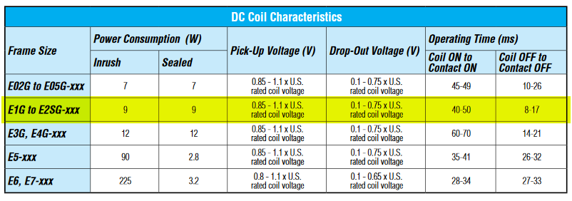
If i understand this correctly, you are saying it is ok to use output from Mega direct to 24v coil side of contactors. Specs below...

Untitled-8-Recovered.png

I thought the Mega is 5v output and I purchased 24v contactors. If my understanding is correct, how does 5v provide enough volts to power a 24v coil? Also, will the 9w draw (x3 contactors = 18w) be too much draw from the single PID output on Mega- thought these were rated around 40mA? What am I missing here?
wd.jpg
 
Last edited:
I'm not inspecting that conversation closely... but: 1. 5V will not drive a 24V device directly, and 2. the MEGA certainly cannot deliver enough current to drive a coil (any coil) directly.

Always make sure that any device driven by an interface output does not exceed its microcontroller limit(s). For the MEGA, you should keep it to under 15mA per pin (that's 0.015A - basically nothing). You always need a solid state front-end to switch low current into high current (example: solid state relay / transistor / etc.). For example, the relay boards we often use have this intermediate front-end circuitry built in. This is why we made the UniShields - to eliminate this headache.
I had a feeling my interpretation of what @crane is suggesting is either wrong or crane doesnt understand the components (specifically the contactors) I have.
My end goal is to use a single PID to drive (3) elements. Each element will have a switch via digital out that allows for separate on/off control either manual or script. This same scenario will occur in HLT and Kettle hence why I have (6) contactors.

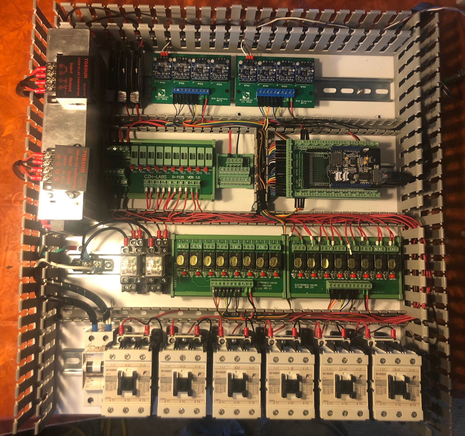
I have pretty much a clean slate to work with as I'm still in planning/wiring phase. I am open to ideas if you have any suggestions. The picture below is the current state of the panel. I had each relay wired to coil side of the contactors but Ive since disconnected those.
IMG_1416.jpg
 
Last edited:
You can use a single binary type output (whether it be a PID, duty cycle, whatever) to drive as many elements as you want. Just need to make sure that each chain in the link is strong enough not to break. It looks like from your picture (can't say for certain without a matching schematic) you have the MEGA outputs going to the relay boards. This is good - they have transistor front ends. From there, those relays can switch power to the contactors. Not sure why you disconnected the relays?

I know I sound like a broken record, but what the heck... you should always draft up a schematic to go with your physical wiring. This way the design can be validated first.
My last post on the topic has a schematic attached for the proposed change. I know the configuration from the relays to the contactors work I was trying to improve my design based on @crane suggestion. This required wiring changes which I was in the middle of verifying in my last few posts (hence why they are disconnected).

It sounds like you are recommending to keep it as I originally had it and use BC to meet this goal. How do you propose I link the (3) digital outs to the PID output? Are you suggesting some script work? Again, I basically want PID running with switches to enable/disable the output of this PID.
 
I had a feeling my interpretation of what @crane is suggesting is either wrong or crane doesnt understand the components (specifically the contactors) I have.
My end goal is to use a single PID to drive (3) elements. Each element will have a switch via digital out that allows for separate on/off control either manual or script. This same scenario will occur in HLT and Kettle hence why I have (6) contactors.

I'm not familiar with the contactor type you are using but are they the traditional magnetic contact coil type or more solid state like an SSR? Reason I ask is have you considered the electrical noise created when a traditional magnetic coil contactor engages and releases high voltage? I had numerous disconnects of my MEGA when switching from my HLT to Boil elements and had to install snubbers across the coils to subdue the electromagnetic noise created upon disconnect. Also if these are magnetic type contact coils you could end up shortening the life of the coil contacts with all the on/off cycling of the PID driving them.
I think you would be better off having your relay setup drive the 24VDC coil on the contactor ON/OFF and then have the PID drive an SSR control input which then controls the high voltage (240VAC) from the contactor thru the SSR.
Yes, I have considered the electric noise. I have planned on using snubbers across the coils to help with noise as well. I dont have much experience with PID and was hoping there was some setting or something to reduce the on/off cycling. Perhaps a hysteresis would be better with the components I have?

I am controlling three elements for one control circuit. Are you saying to incorporate three contactors for ON/OFF and three SSRs for high voltage>?
 
I am controlling three elements for one control circuit. Are you saying to incorporate three contactors for ON/OFF and three SSRs for high voltage>?

Contactor coil ON/OFF thru a relay ( this limits the on/off cycles of the coil + noise) and PID control the input control side of the SSR's for your high voltage from the contactors. Basically you could energize (HLT+Boil)1-6 contactors using script or manual thru relays switching the Common 24VDC to the coils and drive how many elements you want active through a common PID's driving the SSR HLT and Boil.
Of course you would require 6 SSR's to make this happen.
 
Last edited:
Contactor coil ON/OFF thru a relay ( this limits the on/off cycles of the coil + noise) and PID control the input control side of the SSR's for your high voltage from the contactors. Basically you could energize (HLT+Boil)1-6 contactors using script or manual thru relays switching the Common 24VDC to the coils and drive how many elements you want active through a common PID's driving the SSR HLT and Boil.
I currently have each contactor wired to relays and I dont see any issues when I fire the contactors via digital out. Tho I do not have a load on these, not sure it matters cuz I think its the coil side that causes EMI correct? Mega stays on and PT100 readings are stable.

Im stuck on the SSR recommendation. I understand using the PID with SSR as control circuit but are you saying one SSR per HLT and one SSR per kettle or one SSR per contactor? I am planning on 15kw 3phase elements which is why i went with contactors to begin with. Three elements at 15kw is 45k through a common SSR?
 
I currently have each contactor wired to relays and I dont see any issues when I fire the contactors via digital out. Tho I do not have a load on these, not sure it matters cuz I think its the coil side that causes EMI correct? Mega stays on and PT100 readings are stable.

Turning inductive loads on and off rapidly can produce a spark across the contacts thus causing EMI.

Im stuck on the SSR recommendation. I understand using the PID with SSR as control circuit but are you saying one SSR per HLT and one SSR per kettle or one SSR per contactor? I am planning on 12kw 3phase elements which is why i went with contactors to begin with.

Depends, you could as @crane mentions above try PID controling 1 phase thru an SSR and manually switch the other 2 phases (from relay) for quick heating to just below target temp then switch 2 phases off and let the PID take the remaining phase to target. As mentioned 6 SSR's may be overkill but not sure there would be any advantage to achieving target temps since you would be dealing a large mass of heated water/wort almost at the setpoint.
 

Latest posts

Back
Top