BruControl: Brewery control & automation software

Homebrew Talk - Beer, Wine, Mead, & Cider Brewing Discussion Forum

Help Support Homebrew Talk - Beer, Wine, Mead, & Cider Brewing Discussion Forum:

This site may earn a commission from merchant affiliate links, including eBay, Amazon, and others.
Generally, I intend to use the UNI to drive Valves. I can see the real potential for this being the "BruControl" Primary Interface.

My next question deals with P and D switch. I assume that you would normally only use one or the other (P or D). For Valves, You would want to use the "D" Screw Terminal with the appropriate Power connected to the Bank. You would use the "P" Screw Terminal to drive an external SSR or Proportional Controller. Also if you use the Port as other than a Digital Output Type (Digital Input/Counter/One Wire/SPI etc).
Could you give me an example of why you would want it off? Can it be a "general statement" that when using the "P" Screw Terminal, you would normally have the Switch to Off?
and lastly, since you are only wiring to only one Terminal (P or D) , is there a "need" to mess with the switch?

Since this also seems to be a great One Wire board, I will be using Port 5 (Screw Terminal 9-2P) for that. Is that a reason to have the D P Switch off?
 
Another question:

Firmware 45E+

Port Pin 2 is "D, C, O, P, R" and 9-3 on the UNI.
You have 9-3D and 9-3P Screw Terminals.

I would assume that you would use "D" with "9-3D" screw terminal if powering a Valve (even a Proportional One){with appropriate power to the bank}

For Digital Input, Counter, RTD, External SSR or Proportional Controller (like a crydom MCPC1250C: 0-10 Input) via an AA-1, or One wire, use the "9-3P" screw terminal.

Is my thinking correct?
 
I am trying to plan my wiring and settings for the UNI Board.

I have mine set up with a Mega and a Ethernet shield. (BTW, the shields play together well!)

I have read and re read your instruction sheet.

The first question I have is power to the interface.

It looks like you have several choices.

I have 4 power DC sources available for the UNI.

1. Wall Wart Power Supply.
2. 24 vdc Power Supply
3. 12 vdc Power Supply
4. 5 vdc Power Supply

Prior to any Options, set Power Switch to VR Only!
Adjust Power Pot PRIOR to any other Power Switch position.


Obviously there are a lot of Options since you have a DC-DC built into the board.
Option 1: VR Only
1. Wall Wart Power Supply. Obviously the easiest as you simply plug into the Mega. But this uses the on board Mega regulator that may overheat. Leave Power Switch to VR Only

Option 2: Use VR -> VIN and On Board DC-DC

2a. 24 vdc Power: Attach GND to Riser GND and 24 + to VS. Adjust Pot to 7v (7-9v). Then set Power Switch to VR -> VIN.
3a. 12 vdc Power: Attach GND to Riser GND and 12 + to VS. Adjust Pot to 7v (7-9v).Then set Power Switch to VR -> VIN.

Option 3: Use VR -> 5V and On Board DC-DC

2b. 24 vdc Power: Attach GND to Riser GND and 24 + to VS. Adjust Pot to 5v exactly. Then set Power Switch to VR -> 5V.
3b. 12 vdc Power: Attach GND to Riser GND and 12 + to VS. Adjust Pot to 5v exactly. Then set Power Switch to VR -> 5V.
4b. 5 vdc Power: Attach GND to Riser GND and 5 + to VS. Adjust Pot to 5v exactly. Then set Power Switch to VR -> 5V.

I am thinking that Option 2: 3b (12 vdc down to 7v) is the best option. Are any options preferred?

Never use a wall wart. They are crap. If you use a consumer grade power supply , make sure it is a switching unit, used to power a computer device of some sort. I would not use option 1.

OPTION 2: Can use UNLESS you are confident you will overload the MEGA's regulator. If using a WiFi shield and pulling 5V out to power other devices, you may overload it.

OPTION 3: Overload improbable and I think the quality of this power supply is better than the MEGA's regulator. This is the default setting and how we ship it. I would suggest it using it. Only downside is if you opt to pull 5V out for lots of other devices around the rig, that *may* induce noise onto that line which could make the microprocessor go catywampus. In that case, use a discreet 5V PS to power those devices.

BTW your 4b above is not an option. You can't feed 5V in and get 5V out. Vs minimum is 7V, per the manual.
 
Generally, I intend to use the UNI to drive Valves. I can see the real potential for this being the "BruControl" Primary Interface.

My next question deals with P and D switch. I assume that you would normally only use one or the other (P or D). For Valves, You would want to use the "D" Screw Terminal with the appropriate Power connected to the Bank. You would use the "P" Screw Terminal to drive an external SSR or Proportional Controller. Also if you use the Port as other than a Digital Output Type (Digital Input/Counter/One Wire/SPI etc).
Could you give me an example of why you would want it off? Can it be a "general statement" that when using the "P" Screw Terminal, you would normally have the Switch to Off?
and lastly, since you are only wiring to only one Terminal (P or D) , is there a "need" to mess with the switch?

Since this also seems to be a great One Wire board, I will be using Port 5 (Screw Terminal 9-2P) for that. Is that a reason to have the D P Switch off?

You would ALWAYS wire a device to either the P or D terminal for a pin, but NEVER both. For both valves and SSR's, use the D terminal (SSR's draw a few milliamps... better to take that burden off the micro if you can). Proportional (analog) devices can't be driven from this pin, but PWM can.
Per the manual: the switch should be left ON unless we see some weird issue pop up. The pin P is tied to the driver via and has a 100k resistor pulling it down, so if that combination affects the P pin operation, then turning the switch off would make sense. Otherwise, leave them ON. You could follow your general statement, but I think there is more risk in opening the UniShield and flipping switches than there is to leave them alone unless needed.

Regarding 1-wire... I do not think the 100k resistor and high driver impedance will matter since there is a 4.7k resistor tying the 1-wire signal to 5V power, but honestly we don't have enough experience. If you are concerned, or changing it will be difficult post installation, go ahead and flip this switch OFF.
 
Another question:

Firmware 45E+

Port Pin 2 is "D, C, O, P, R" and 9-3 on the UNI.
You have 9-3D and 9-3P Screw Terminals.

I would assume that you would use "D" with "9-3D" screw terminal if powering a Valve (even a Proportional One){with appropriate power to the bank}

For Digital Input, Counter, RTD, External SSR or Proportional Controller (like a crydom MCPC1250C: 0-10 Input) via an AA-1, or One wire, use the "9-3P" screw terminal.
Is my thinking correct?

Yes, D for powering a valve, but not a proportional one unless it takes a PWM input signal. Remember that P stands for PWM, not proportional. You can convert the PWM to analog-ish with a resistor-capacitor circuit, or feed it to the analog amplifier board to generate a legit, powered, analog signal.

For DI, RTD, PWM --> AA-1, 1-wire, then yes use P. Per above, power SSR with the D.
 
Has anyone gotten the SunFounder 20X4 LCD panel to work rather than the Adafruit 198 & 292 option? I am trying to get the one below to work. The panel comes on but can not get it to display any text. Double checked wiring and contrast.

https://www.amazon.com/SunFounder-Interface-Backlight-Raspberry-MEGA2560/dp/B07MTFDHXZ

I don't think it will work... they use different I/O chips on them. You could possibly get the Adafruit 292 and swap it over if unsoldering/soldering that bank is possible. Might be tricky! Sorry!
 
Never use a wall wart. They are crap. If you use a consumer grade power supply , make sure it is a switching unit, used to power a computer device of some sort. I would not use option 1.

OPTION 2: Can use UNLESS you are confident you will overload the MEGA's regulator. If using a WiFi shield and pulling 5V out to power other devices, you may overload it.

OPTION 3: Overload improbable and I think the quality of this power supply is better than the MEGA's regulator. This is the default setting and how we ship it. I would suggest it using it. Only downside is if you opt to pull 5V out for lots of other devices around the rig, that *may* induce noise onto that line which could make the microprocessor go catywampus. In that case, use a discreet 5V PS to power those devices.

BTW your 4b above is not an option. You can't feed 5V in and get 5V out. Vs minimum is 7V, per the manual.

Option 3: Use VR -> 5V and On Board DC-DC

3b. 12 vdc Power: Attach GND to Riser GND and 12 + to VS. Adjust Pot to 5v exactly. Then set Power Switch to VR -> 5V.

This is what I will use.

I have a separate 5vdc Power Supply for anything except the 10K NTC Probes that requires 5 vdc AREF with the TF3 boards.
 
While your instructions are fairly clear, I just wanted to check the Dip Switch settings on the UNI board as I will be covering it up with my Ethernet Shield.

Most is for future planning as I have most of my wiring done for a Standard Mega with Ethernet for Hot Side Brewing. I do plan to generally use the UNI to control a lot of valves in my manifold (manual valves now) I wish I had had the UNI a year ago although I would have needed a second one regardless to do what I want. I have 8 hot side vessels and can make 3 batches at a time, although we generally only make 2.

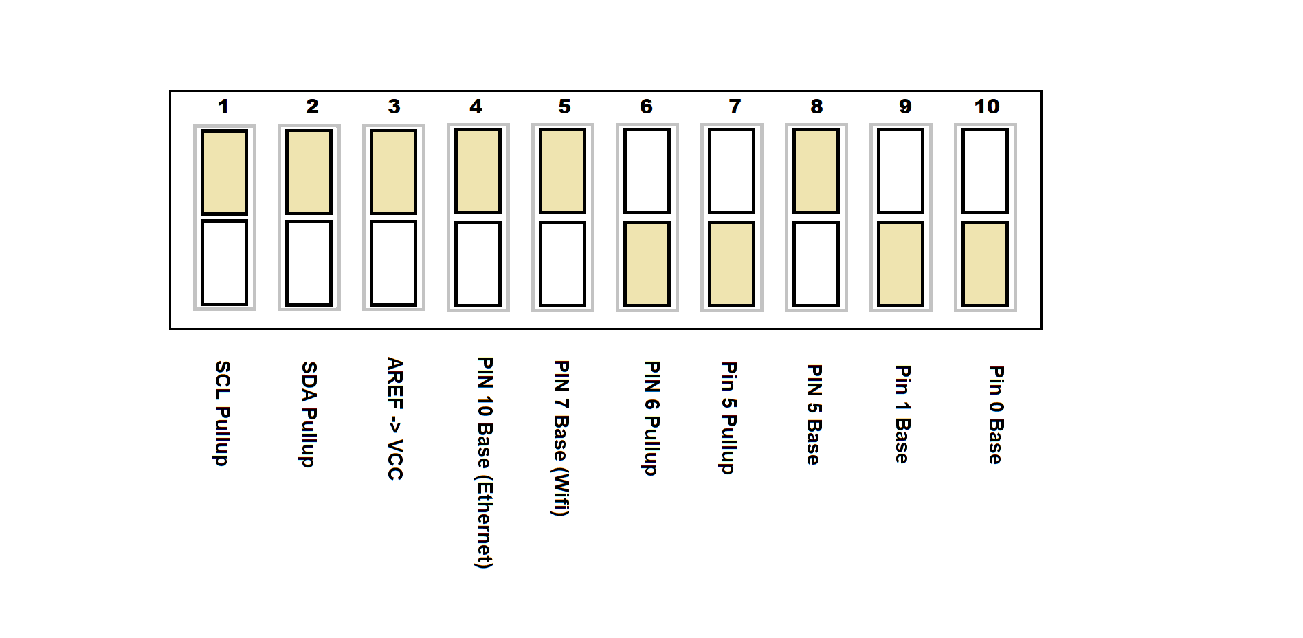
I received the UNI with the default No Communication Shield configuration:

uni dip Default No Shield.png

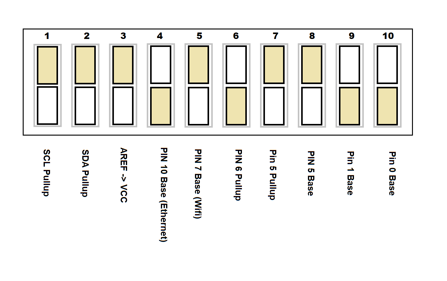
1. I am moving Dip 4 (Pin 10 Base) to Off for the Ethernet Shield.
2. I am leaving Dip 5 (PIn 7 Base) to ON so that I can use Port 7 {Screw Terminals 8-4P or D}
3. I am leaving Dip 6 (Pin 6 Pullup) to Off so that I can use Port 6 {Screw Terminals 8-3P or D} for D, P, R (not using for "O".
4. I am moving Dip 7 (Pin 5 Pullup) to ON for to use Port 5 for One Wire "O"
5. I am moving Dip 8 (Pin 5 Base) to ON for to use Pin 5 {Screw Terminal 9-2D.} (Ports 200-209) for One Wire "O"


Is this correct?

Also since DIP 3 (AREF -> VCC) is ON, should I use the UNI VCC Pin to supply the referenced 5+ power to a TF-3 VCC?

my plan dip switches.png
 
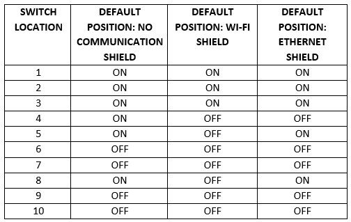
Here is the sections from the Manual:
upload_2020-3-19_17-14-57.png


Your diagram doesn't show ON or OFF, or which color is which, but assuming tan up is ON, then you have it matching other than 7. As you noted, you want to use 1-Wire, so you can turn on switch 7 to enable the 4.7k pullup and avoid needing one externally. So yes, you have it correct.
 
Here is the sections from the Manual:
View attachment 671689

Your diagram doesn't show ON or OFF, or which color is which, but assuming tan up is ON, then you have it matching other than 7. As you noted, you want to use 1-Wire, so you can turn on switch 7 to enable the 4.7k pullup and avoid needing one externally. So yes, you have it correct.
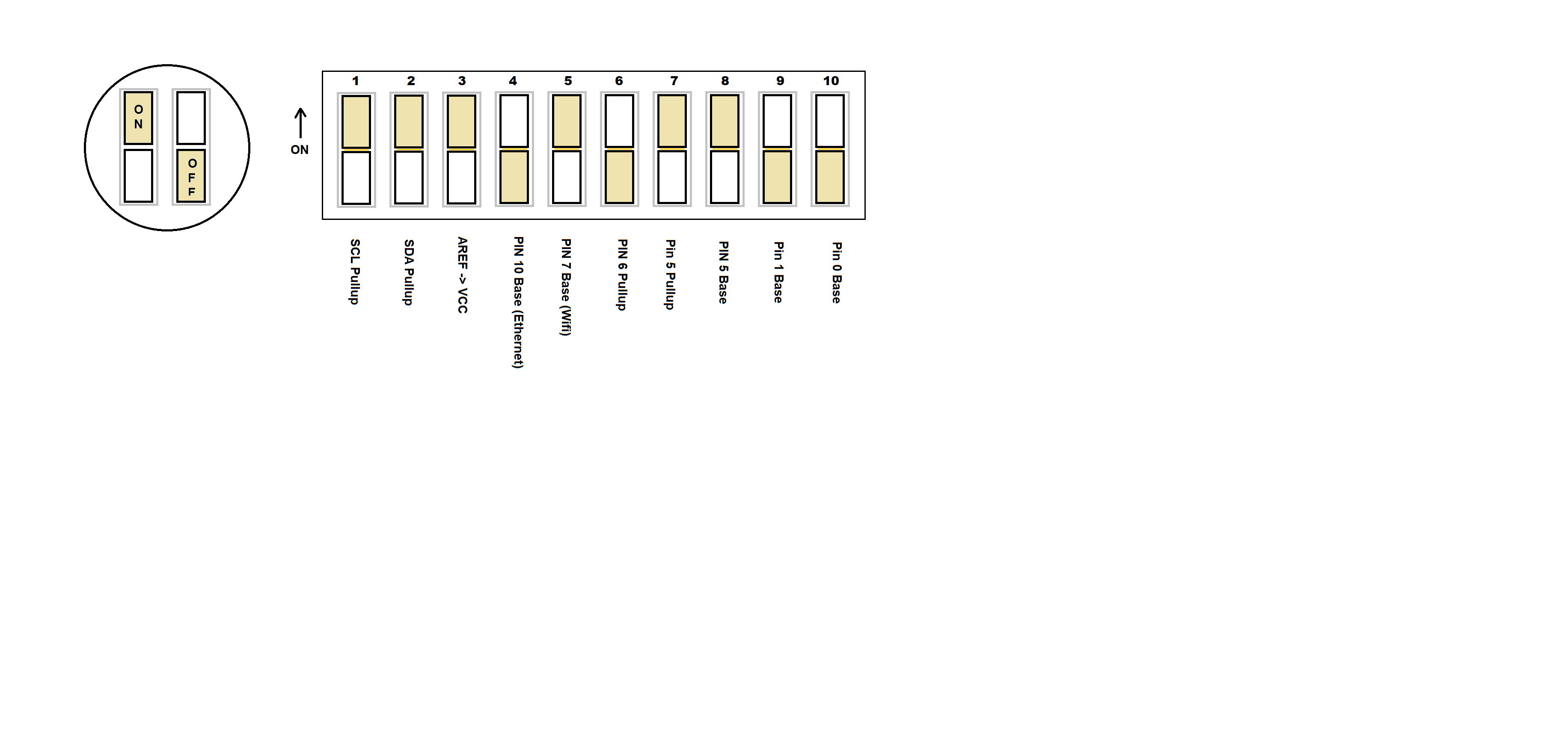
On/Off as shown. Thanks.
uni dip Default Plan 1.png
 
Assuming that Interface Map v45E+ is good for v45H. The + means versions 45E to current version 45H?

I know that you may not have to update the firmware to every new version as a "fix" or item may only apply to certain situations, but until I get into a true "production" mode, I am updating with every release.
 
In the manual Regarding PWM Output:

"such as a low pass filter to convert the PWM Output to an Analog Output. See the Schematics section on BruControl’s website for details."

I am not sure which Schematics is the one I should be looking at. I am intending to buy one of your Proportional Valves (http://brucontrol.com/buy/valves/).

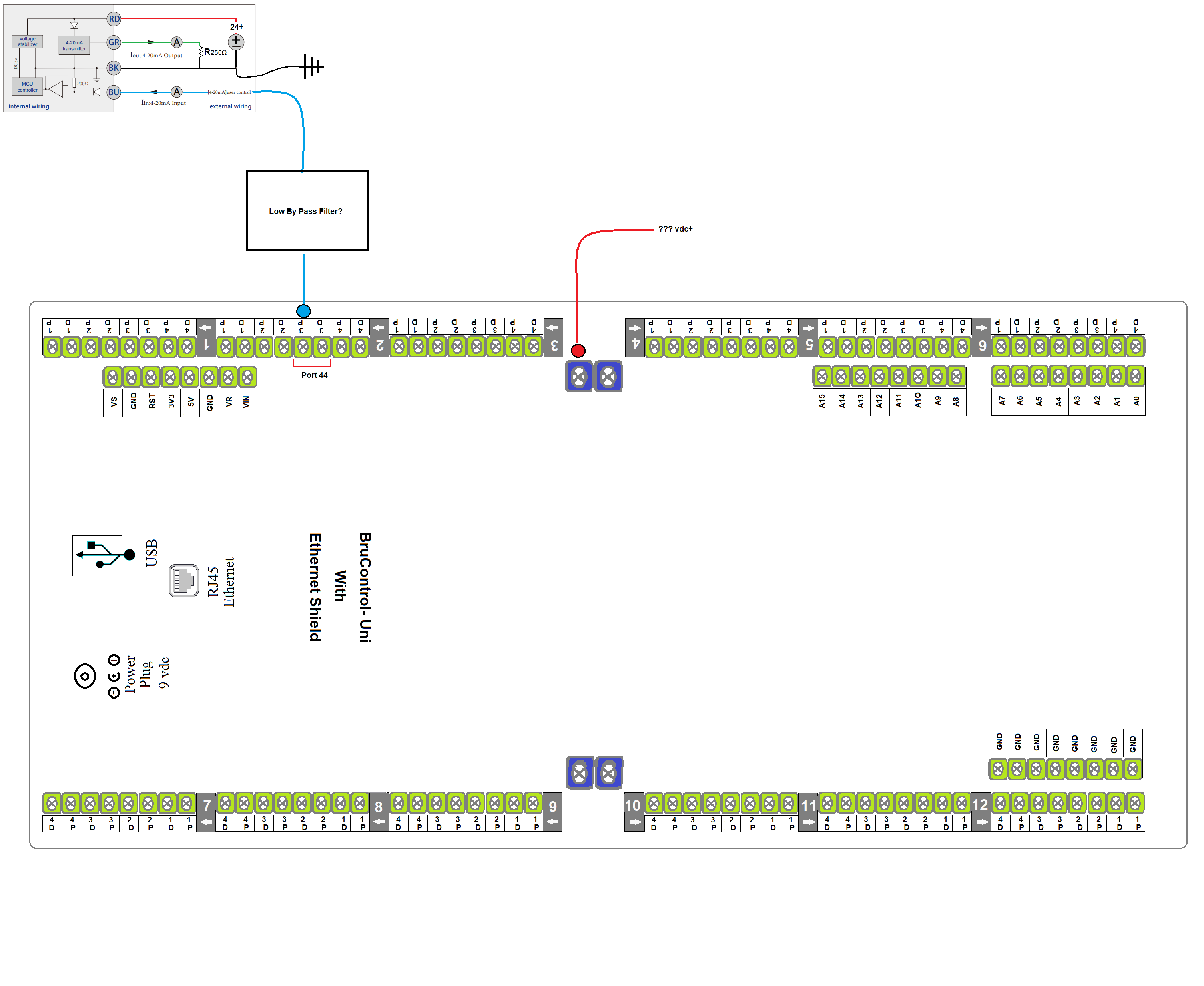
I will be using a UNI with Mega 2560 to control the valve. I am planning on using Port 44 (D, P, R) Screw Terminal 2-3P for "P")

Is this an Off the shelf Filter that would work. I do not see much in instructions on the Valve.

https://www.dfrobot.com/product-1755.html

low pass filter dfrobot.png


I do see this but not sure how and where you would hook in a low bypass filter.

Proportional Valve circuit.png
 
You already have the AA-1. That is your low pass filter.

The manual will now read: "... such as a low pass filter or BruControl Analog Amplifier Model AA-1 or AA-2 to convert the PWM Output to an Analog Output."

More detail for those interested... The microcontrollers used in Arduino etc. often do not output true analog voltage, but do output PWM (Pulse Width Modulation), which is a square wave. The square wave is a voltage that essentially goes from zero (ground) to micro's voltage and back almost instantly, and that cycling occurs at a rapid rate (say, 1000 times per second). The amount of time the square wave spends ON:OFF determines the PWM's output percentage. On for half the cycle and off for the other half means the PWM output is 50%. PWM gets converted to analog in a "low pass filter" which means only the low frequency gets through. Simple filter includes just a current limiting resistor in series with a capacitor to ground. This causes the relatively slow capacitor to charge up a little, then discharge a little. Because the charging and discharging occur so slowly, the output of this circuit is essentially flat at a voltage commensurate with the micro's output. This type of filter is cheap and easy to implement... but like all things there is no free lunch, so the downside is they are "slow" to react. Slow in the circuitry/physical world, but certainly fast enough in the brewing world, where everything happens at a molasses pace as far as electronics are concerned. The BruControl AA-1 or AA-2 has a resistor-capacitor front end on it, but then adds an op-amp to multiply that voltage to a range you can use to drive a proportional device... such as 0-10V for a proportional valve. Hope that helps!
 
Last edited:
OK A couple of questions regarding the AA-1 (or an AA-2).

1. If you have devices that require different V+ Voltages ie 12 v and 24 volts, can you supply that voltage external to the AA-1 (or AA-2) or do you need to send the Voltage via the V+ Out Pin of the Analog Amplifier? If needed to send through the Analog Amplifier, then I guess you would need a 12v Analog Amplifier and a 24 v Analog Amplifier, if you had those requirements.

2, The instructions are fairly clear on 0-5 and 0-10 v, but how about the 4-20mA signal? The Proportional valve looks like it takes a 4-20mA input. How would you set a AA- 1(or AA-2) Amplifier Potentiometer for 4-20mA?

Please excuse if this is "simple" question as I have never worked with 4-20mA.
 
Good questions. The voltage in to the AA is to drive the circuitry but we also provided the pass-through to make your wiring easier. For example 4 valves each need power, ground, and control signal, so we added terminals so you can easily wire all 12 wires directly to the AA. You don’t need to use the pass through, so you can wire your devices to power separately. If you had 12 and 24V devices which used the same control signal range, you could wire the 12V devices to the AA pass through and the 24V devices to a 24V power supply, and wire control signal for both from the AA.

The proportional valve we sell is 0-5V control, not 4-20mA. Pic shows 0-5V control and 4-20mA feedback loop.

You *could* drive a 4-20 mA device but need to keep wiring short and know it’s impedance to create a proper circuit. It won’t be 100% accurate but close enough. I’d avoid it if you can but if in a pinch it can be done.

edit: Corrected the middle sentence above re: valve's control.
 
Last edited:
I finally got to ask for help with something I'm trying to get to work with my script. I'm trying to track how many times a valve opens and closes through the duration the script is running. I can't find anything about this, and I've spent too much time trying to get it to work, any help would be greatly appreciated.
 
I was reading though the UNI Instructions for another time (about the 1000th) and I am finally getting my head around the concept of the "P" and "D" Screw Terminals. The "P" Screw Terminal is just like a Port/Pin on a regular Mega 2560 (if that is the interface you are using) as if there was no UNI. The "D" Terminal has its own On Board DC Relay that can power a DC Item such as a Valve without any else rather than the Valve Power and Ground wires run to the selected UNI "D" Screw Terminal and Ground Terminal. The Output Voltage of a D"" Screw Terminal is dependent on the supplied Power to the Blue Terminals for the Bank. AC Items and high Load DC Items would need an separate SSR and you could use the "D" Screw Terminal as the "Control" signal. PWM signals would need to be sent to items such as an Analog Amplifier using the "P" Screw Terminal. In addition, any PWM control would need to have the "P = PWM Output (Note: Output ...)" in the Interface Wiring Map for the selected UNI "P" Screw Terminal.

Digital Inputs, Counters, PID, Deadband would always use the "P" Screw Terminal with any additional requirements (Float, Hall Effect...)for them to operate.

The "D" Screw Terminals would drive and Power DC On/OFF type items, such as DC Valves or AC SSRs (On/Off) or high Amperage DC SSRs (On/Off) for loads that exceed the On Board DC Relay.

Do I have it down?

BTW, I was confused by the "P" Screw Terminal and the "P" of the Interface Wiring Map. The only connection I see is that if you want to use PWM, you need to choose a Port/Pin/ UNI Screw Terminal" that has a "P": PWM on the Interface Wiring Map and use the "P" Screw Terminal for the control signal to something like the Analog Amplifier. Otherwise, the "P" Screw Terminal is just the associated PIN/Port of the Interface (Mega 2560 in my case).
 
I finally got to ask for help with something I'm trying to get to work with my script. I'm trying to track how many times a valve opens and closes through the duration the script is running. I can't find anything about this, and I've spent too much time trying to get it to work, any help would be greatly appreciated.
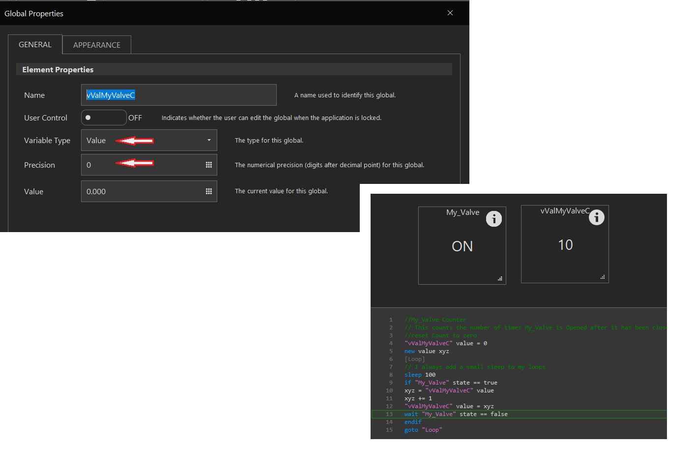
1. Create a Global Element named something like : vValMyValveC
This should be a Value Type with Precission 0.

2. You can assume that your valve name is My_Valve. Substitute your valve element name for My_Valve


You add these lines to a house keeping looping script (Always running when other scripts are also running. I would make this a separate script because it waits until "My_Valve" state == false.


//My_Valve Counter
// This counts the number of times My_Valve is Opened.
//reset Count to zero
"vValMyValveC" value = 0
new value xyz
[Loop]
// I always add a small sleep to my loops
sleep 100
if "My_Valve" state == true
xyz = "vValMyValveC" value
xyz += 1
"vValMyValveC" value = xyz
wait "My_Valve" state == false
endif
goto "Loop"

vValMyValveGlobal.png
 
I was reading though the UNI Instructions for another time (about the 1000th) and I am finally getting my head around the concept of the "P" and "D" Screw Terminals. The "P" Screw Terminal is just like a Port/Pin on a regular Mega 2560 (if that is the interface you are using) as if there was no UNI. The "D" Terminal has its own On Board DC Relay that can power a DC Item such as a Valve without any else rather than the Valve Power and Ground wires run to the selected UNI "D" Screw Terminal and Ground Terminal. The Output Voltage of a D"" Screw Terminal is dependent on the supplied Power to the Blue Terminals for the Bank. AC Items and high Load DC Items would need an separate SSR and you could use the "D" Screw Terminal as the "Control" signal. PWM signals would need to be sent to items such as an Analog Amplifier using the "P" Screw Terminal. In addition, any PWM control would need to have the "P = PWM Output (Note: Output ...)" in the Interface Wiring Map for the selected UNI "P" Screw Terminal.

Digital Inputs, Counters, PID, Deadband would always use the "P" Screw Terminal with any additional requirements (Float, Hall Effect...)for them to operate.

The "D" Screw Terminals would drive and Power DC On/OFF type items, such as DC Valves or AC SSRs (On/Off) or high Amperage DC SSRs (On/Off) for loads that exceed the On Board DC Relay.

Do I have it down?

BTW, I was confused by the "P" Screw Terminal and the "P" of the Interface Wiring Map. The only connection I see is that if you want to use PWM, you need to choose a Port/Pin/ UNI Screw Terminal" that has a "P": PWM on the Interface Wiring Map and use the "P" Screw Terminal for the control signal to something like the Analog Amplifier. Otherwise, the "P" Screw Terminal is just the associated PIN/Port of the Interface (Mega 2560 in my case).

Yes... the P terminal is directly tied to the port/pin on the MEGA. The D terminal is the output of a high current driver (not relay) which is tied to the P terminal. The D terminal outputs the same voltage fed to its bank (via blue terminals, e.g. VA).

Don't think of device element types for P or D association... think of whether they are inputs or outputs. Inputs like counters will always use P terminals and outputs will likely use D if you want to drive high current & voltage (PID and Deadband are output devices). It depends on what you are driving. Need high current (>10mA)? Then use the driver (D) terminal. You can still use a P pin for output, it is just low current like using a MEGA without the UniShield.

And here's another thought... you can use the PWM output through the D terminals... it will create a high voltage & current output. You could modulate, for example, a small DC pump using this, for example, a Topsflo TD-5. Remember this is PWM output, not analog. You can use the PWM through the P pin to feed the analog amplifier because the AA uses very little current and its voltage input range is 3.3 - 5V.
 
Your Proportional Valve:
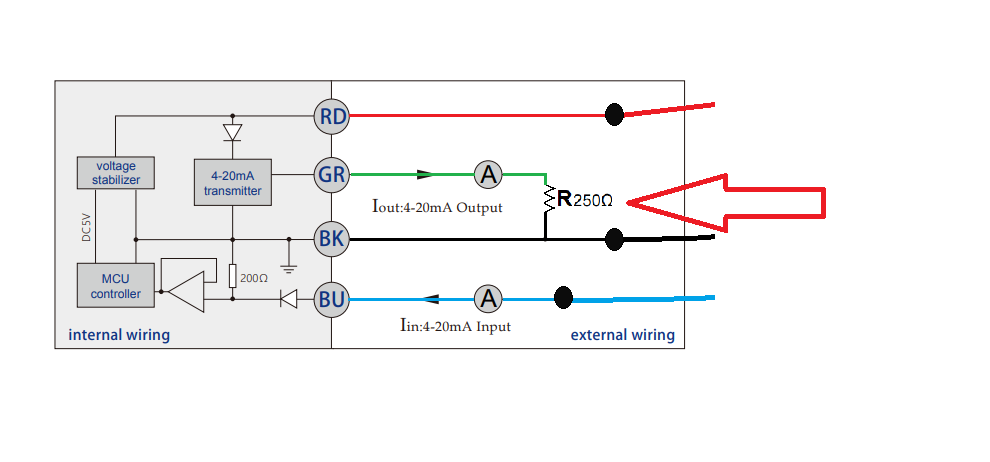
Do I need View attachment 672037 the 250 ohm resistor circuit if supplying the Blue Control signal from an AA-1 Analog Amplifier?

No. The proportional valve we sell is 0-5V input, not 4-20mA input. The brochure shows 4-20mA but it is 0-5V. I suggest you don't use the feedback (output) of the valve - it is not necessary.
 
OK. Thanks. Your Analog Amplifier solve a lot of my lack of electronic understanding. With the on board Pull Down Resistors on the UNI for One Wire Probes solves another lacking (PCB soldering skills). Sorry for the 1000 questions but I do not really want to become an electronics expert, just Brew Great Beer!
 
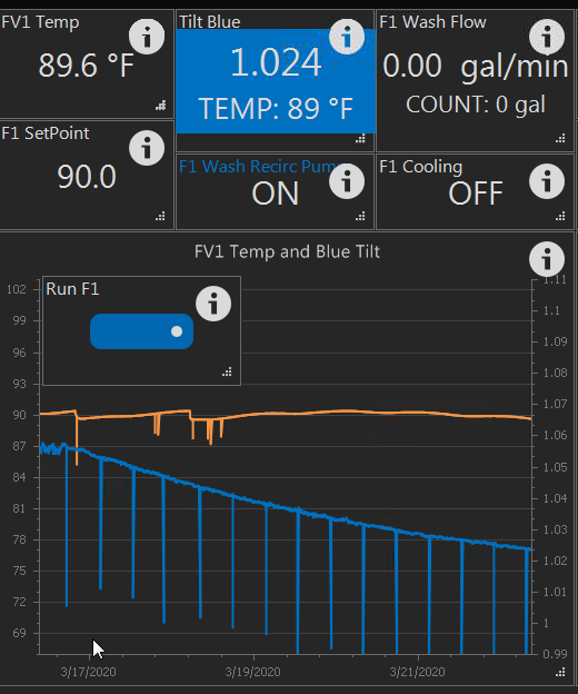
We think the drop is related to the interaction between Wi-Fi and BlueTooth. I think we have a beat on it... just need to get it done. Been focusing on some hardware lately but will get some time on it. If the drops are brutal... use a script to read values off the Tilt, write those values into a Global except for those which are a % off of the existing trend. You will get a smooth data line then. A workaround for now.
 
I am still have trouble with the LCDs. I replaced the SunFounder LCDs I had with Adafruit 198 & 292 configuration. I have the LCD connected directly to a 5v power supply and have verified power. I am using the Electronics Salon screw shield for the Mega. I have DAT terminal on LCD wired to SDA screw terminal for Mega and CLK on LCD wired to SCL screw terminal for Mega. The LCD powers up, and I am able to turn on and off the backlight by sending the following but I cannot get it to display any text. I have two of the Adafruit LCDs with daughter board and two different Megas and get same results regardless of the combination.

I am sure I am missing something easy. Does the LCD have to be "enabled" somewhere or a device added that I missed when looking? Any help is appreciated.

Turn backlight on and off (works great)

new string LCD1
[loop]
LCD1 = "0"
display "BREW1" 0 "LCD1"
sleep 10000
LCD1 = "1"
display "BREW1" 0 "LCD1"
sleep 10000
goto loop

Script to display text - Does not work / no text displayed

new string LCD2
[loop]
LCD2 = "Test Text"
display "BREW1" 1 "LCD2"
Sleep 10000
LCD2 = "Hello World"
display "BREW1" 1 "LCD2"
sleep 10000
goto loop
 
Tilt via ESP32 seems to have a far too regular drop, any thoughts? The same ESP is also doing the RTD temp in the display.

It looks like pretty regular intervals that your ESP32 is dropping, and I had the same issue so this might apply to you. My router was doing ARP scans every so often and the ESP32 doesn't like it and reboots. Its repeatable, so it might be worth looking into on your network.
 
Tilt via ESP32 seems to have a far too regular drop, any thoughts? The same ESP is also doing the RTD temp in the display.
View attachment 672221
I notice that the Blue Tooth drops on the Tilt quite a bit. I am thinking it is more of a Tilt issue rather than the ESP as I have seen it on the Iphone App as well. Would a FLOOR Calibration work?
 
Makes little sense that the LCD backlight is turning on and off but the text isn't showing. The communication is working if the backlight is responding.

I just tested this with success (on a Feather interface named "Refrigeration", not on a MEGA though).

Code:
new string LCD2
[loop]
LCD2 = "Test Text"
display "Refrigeration" 1 LCD2
sleep 10000
LCD2 = "Hello World"
display "Refrigeration" 1 LCD2
sleep 10000
goto loop


I do have it wired to SDA and SCL on the screw shield rather than Pin 20 and 21 that I have seen elsewhere for the Mega. I am guessing that is correct since the backlight command works but thought I should double check.
 
1. Create a Global Element named something like : vValMyValveC
This should be a Value Type with Precission 0.

2. You can assume that your valve name is My_Valve. Substitute your valve element name for My_Valve


You add these lines to a house keeping looping script (Always running when other scripts are also running. I would make this a separate script because it waits until "My_Valve" state == false.


//My_Valve Counter
// This counts the number of times My_Valve is Opened.
//reset Count to zero
"vValMyValveC" value = 0
new value xyz
[Loop]
// I always add a small sleep to my loops
sleep 100
if "My_Valve" state == true
xyz = "vValMyValveC" value
xyz += 1
"vValMyValveC" value = xyz
wait "My_Valve" state == false
endif
goto "Loop"

View attachment 672035

I would ditch the delay and if and just have 2 waits. This eliminates the polling.

[Main]
"vValMyValveC" value = 0

[Loop]
wait My_Valve" state == true
"vValMyValveC" value += 1
wait "My_Valve" state == false
goto "Loop"
 
I would ditch the delay and if and just have 2 waits. This eliminates the polling.

[Main]
"vValMyValveC" value = 0

[Loop]
wait My_Valve" state == true
"vValMyValveC" value += 1
wait "My_Valve" state == false
goto "Loop"

Smart. Like the two waits. I guess the difference from the if end if is that it does not Loop until off, so one loop per On the Off Cycle. Much more elegant.

I had a problem with the

"vValMyValveC" value += 1


Not sure if that math (+=) works on a Global Element Value. I posted your suggestion into my sandbox and got the following error (same one I got when I was building it as I tried that += first.)

[ERROR: '+=' is not a valid operator]

This math does work without using a variable:

vValMyValveC value = vValMyValveC value + 1


My suggested code now:

"vValMyValveC" value = 0
[Loop]
wait "My_Valve" state == true
"vValMyValveC" value = "vValMyValveC" value + 1
wait "My_Valve" state == false
goto "Loop"
 
Last edited:
Back
Top