So sorry. I'm not familiar with those switches. (They are illuminated units? No?)I purchased the switches from automation direct. This is what they came with.
You are using an out of date browser. It may not display this or other websites correctly.
You should upgrade or use an alternative browser.
You should upgrade or use an alternative browser.
BCS-460, 3 elements, 2 pumps
- Thread starter Beeskneesbrew
- Start date

Help Support Homebrew Talk:
This site may earn a commission from merchant affiliate
links, including eBay, Amazon, and others.
Beeskneesbrew
Well-Known Member
Yes, they are the same part number you listed on the diagram.
Beeskneesbrew
Well-Known Member
If that helps you at all.
Yes, they are the same part number you listed on the diagram.
Ok...If that helps you at all.
???
Beeskneesbrew
Well-Known Member
Will they work for your diagram?
Yes. I've already covered the issues regarding these switches in this thread:Will the work for your diagram?
post#3613995
And
post#3714201
And
post#3714938
Bottom line is the switches will need additional N/O modules to function in the application shown in the diagram. The N/C modules are not needed.


$33.99 ($17.00 / Count)
$41.99 ($21.00 / Count)
2 Pack 1 Gallon Large Fermentation Jars with 3 Airlocks and 2 SCREW Lids(100% Airtight Heavy Duty Lid w Silicone) - Wide Mouth Glass Jars w Scale Mark - Pickle Jars for Sauerkraut, Sourdough Starter
Qianfenie Direct

$20.94
$29.99
The Brew Your Own Big Book of Clone Recipes: Featuring 300 Homebrew Recipes from Your Favorite Breweries
Amazon.com

$19.99
$22.99
How To Brew: Everything You Need to Know to Brew Great Beer Every Time
Simon & Schuster Digital Sales LLC


$53.24
1pc Hose Barb/MFL 1.5" Tri Clamp to Ball Lock Post Liquid Gas Homebrew Kegging Fermentation Parts Brewer Hardware SUS304(Liquid Hose Barb)
yunchengshiyanhuqucuichendianzishangwuyouxiangongsi


$172.35
2 Inch Tri Clamp Keg Manifold With Ball Lock Posts, Pressure Gauge, PRV (0-30 PSI) – Homebrew, Fermentation, Kegging System
wuhanshijiayangzhiyimaoyiyouxiangongsi


$479.00
$559.00
EdgeStar KC1000SS Craft Brew Kegerator for 1/6 Barrel and Cornelius Kegs
Amazon.com


$176.97
1pc Commercial Keg Manifold 2" Tri Clamp,Ball Lock Tapping Head,Pressure Gauge/Adjustable PRV for Kegging,Fermentation Control
hanhanbaihuoxiaoshoudian

$53.24
1pc Hose Barb/MFL 1.5" Tri Clamp to Ball Lock Post Liquid Gas Homebrew Kegging Fermentation Parts Brewer Hardware SUS304(Gas MFL)
Guangshui Weilu You Trading Co., Ltd

![Craft A Brew - Safale S-04 Dry Yeast - Fermentis - English Ale Dry Yeast - For English and American Ales and Hard Apple Ciders - Ingredients for Home Brewing - Beer Making Supplies - [1 Pack]](https://m.media-amazon.com/images/I/41fVGNh6JfL._SL500_.jpg)
$6.95 ($17.38 / Ounce)
$7.47 ($18.68 / Ounce)
Craft A Brew - Safale S-04 Dry Yeast - Fermentis - English Ale Dry Yeast - For English and American Ales and Hard Apple Ciders - Ingredients for Home Brewing - Beer Making Supplies - [1 Pack]
Hobby Homebrew


$7.79 ($7.79 / Count)
Craft A Brew - LalBrew Voss™ - Kveik Ale Yeast - For Craft Lagers - Ingredients for Home Brewing - Beer Making Supplies - (1 Pack)
Craft a Brew


$719.00
$799.00
EdgeStar KC2000TWIN Full Size Dual Tap Kegerator & Draft Beer Dispenser - Black
Amazon.com


$76.92 ($2,179.04 / Ounce)
Brewing accessories 1.5" Tri Clamp to Ball Lock Post Liquid Gas Homebrew Kegging Fermentation Parts Brewer Hardware SUS304 Brewing accessories(Gas Hose Barb)
chuhanhandianzishangwu

$44.99
$49.95
Craft A Brew - Mead Making Kit – Reusable Make Your Own Mead Kit – Yields 1 Gallon of Mead
Craft a Brew


$28.98
Five Star - 6022b_ - Star San - 32 Ounce - High Foaming Sanitizer
Great Fermentations of Indiana


$22.00 ($623.23 / Ounce)
AMZLMPKNTW Ball Lock Sample Faucet 30cm Reinforced Silicone Hose Secondary Fermentation Homebrew Kegging joyful
无为中南商贸有限公司


$58.16
HUIZHUGS Brewing Equipment Keg Ball Lock Faucet 30cm Reinforced Silicone Hose Secondary Fermentation Homebrew Kegging Brewing Equipment
xiangshuizhenzhanglingfengshop


$11.99
DERNORD 1/2 Inch Stainless Steel Quick Disconnect Set - Beer Brewing Connector Kit (Barb Female/FPT Male)
denuodianqiyouxiangongsi

$10.99 ($31.16 / Ounce)
Hornindal Kveik Yeast for Homebrewing - Mead, Cider, Wine, Beer - 10g Packet - Saccharomyces Cerevisiae - Sold by Shadowhive.com
Shadowhive


Beeskneesbrew
Well-Known Member
Is there anyone that has followed this diagram, that has pictures inside and out of their control panel?
Beeskneesbrew
Well-Known Member
But just switches 5-7 correct PJ?
That is correct. For those switches you need another pair of N/O modules added to provide the function needed.But just switches 5-7 correct PJ?
Good Morning P-J,
I have finnally gotten the entire brew rig together but I am running into an issue. On the heating element/element legs i am not getting the voltage reading I would expect. I have hem hooked up like so: one 120 leg to one point in the plug another 120 leg on the oposite leg and a ground hooked to the ground leg. In the schematic all three are hooked up exactly like I have them but I am getting no voltage when testing between ground leg and either one of the 120 legs. At this point I was thinking I misunderstood your directions and thought the gound leg should be the common and when testing between the common and either one of the legs I see 12v ac weather on or not... Do you know what this may be or why I would be getting this tickle voltage?
Thanks for all your help
cd
This really sounds like you have a wiring error some where.Good Morning P-J,
I have finnally gotten the entire brew rig together but I am running into an issue. On the heating element/element legs i am not getting the voltage reading I would expect. I have hem hooked up like so: one 120 leg to one point in the plug another 120 leg on the oposite leg and a ground hooked to the ground leg. In the schematic all three are hooked up exactly like I have them but I am getting no voltage when testing between ground leg and either one of the 120 legs. At this point I was thinking I misunderstood your directions and thought the gound leg should be the common and when testing between the common and either one of the legs I see 12v ac weather on or not... Do you know what this may be or why I would be getting this tickle voltage?
Thanks for all your help
cd
Is it possible for you to take some detail photos of the wiring so that I might be able to help you?
If that is possible, let me know and I'll PM you my E-Mail addy so that you can send them. (If you post them, they will be way too small to see properly. Unless you can host them and then link them as I do.)
P-J
Beeskneesbrew
Well-Known Member
Did some control panel work tonight! Switches have all been mounted.


Stupid question, and I'll admit to not reading this thread through, but is your BCS plugged in when you're testing? I have a similar system with a BCS and two pumps and found that you absolutely need the BCS in the circuit. It supplies the 12V DC to the relays. They won't open without 12V DC, even if your system has a manual switch override.
Just a thought. . .probably dumb.
Just a thought. . .probably dumb.
Beeskneesbrew
Well-Known Member
I'm not sure....haven't gotten that far yet. Im sure PJ has the answers! Care to share any pictures of your setup?
Beeskneesbrew
Well-Known Member
Plove, I think the answer to your question is on page 7. It talks about the 5v power adapter.
Beeskneesbrew
Well-Known Member
PJ, do you have diagram that incorporates volt and amp meters into this same setup?
No. I don't incorporate meters in the diagrams that I draw. I feel that they serve no purpose as they only show the input voltage & current and those values are already known.PJ, do you have diagram that incorporates volt and amp meters into this same setup?
Sorry.
P-J
Beeskneesbrew
Well-Known Member
How would I go about adding these if I wanted them more for looks? I think they would look good on both sides of the e-stop.
Check out Kal's site:
Here is a link to his meter wiring plan:
http://www.theelectricbrewery.com/control-panel-part-2?page=9
Here is a link to his meter wiring plan:
http://www.theelectricbrewery.com/control-panel-part-2?page=9
Beeskneesbrew
Well-Known Member
More parts today, waiting for SSR's!


Beeskneesbrew
Well-Known Member
So I was just looking at the diagram, and was wondering if all the wiring coming from the bcs and going to the switches, ssr's and contactors could use low voltage wiring? I plan on using 10 gauge for everything else. Does this sound correct?
bullywee
Well-Known Member
Beeskneesbrew said:So I was just looking at the diagram, and was wondering if all the wiring coming from the bcs and going to the switches, ssr's and contactors could use low voltage wiring? I plan on using 10 gauge for everything else. Does this sound correct?[/
bullywee
Well-Known Member
From the BCS to SSR's I did cat 5, to contacters (120) 14 or 16, switches 14 or 16, pumps 14 or 16. On the 240 side 10.
hatrickwah
Sponsor
bullywee said:From the BCS to SSR's I did cat 5, to contacters (120) 14 or 16, switches 14 or 16, pumps 14 or 16. On the 240 side 10.
I did the same. I did 14 for all my 110. 10 for the individual 220 element circuits. And 22 on the low voltage. Only used cat5e for my temp probes and networking. Works flawlessly.
hatrickwah
Sponsor
hatrickwah said:I did the same. I did 14 for all my 110. 10 for the individual 220 element circuits. And 22 on the low voltage. Only used cat5e for my temp probes and networking. Works flawlessly.
Did similar in my own BCS setup. Used 22# on my low voltage and 14 for 110v. 10# for 220v side.
kosmokramer
Well-Known Member
Did similar in my own BCS setup. Used 22# on my low voltage and 14 for 110v. 10# for 220v side.
Lol... i think you commented on your own post that time.

hatrickwah
Sponsor
kosmokramer said:Lol... i think you commented on your own post that time.
Perhaps
")
Beeskneesbrew
Well-Known Member
Mr. Wah any chance I can get a close up on how you wired your switches in the bcs rig?
kosmokramer
Well-Known Member
From the BCS to SSR's I did cat 5, to contacters (120) 14 or 16, switches 14 or 16, pumps 14 or 16. On the 240 side 10.
some closeups of this would be great to if you have a spare minute. Im just about to start wiring mine up
hatrickwah
Sponsor
Can do. I'll post them tonight. Let me either dig something out or take a few. I know I snapped a close up of the switches. Any other close ups you would like?
Beeskneesbrew
Well-Known Member
Any close UPS you have would help a ton!
hatrickwah
Sponsor
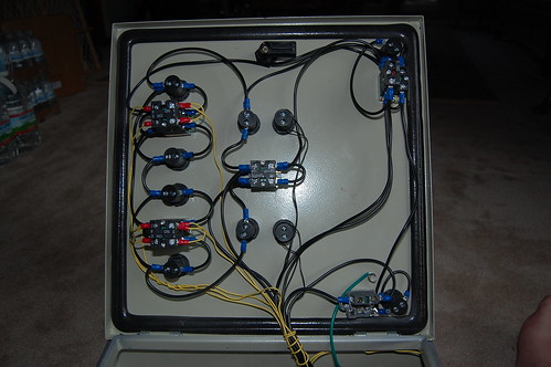
These pictures are of a new setup I finished tonight. One I'm building for no-one in particular yet. Call it a challenge if you will, to then put up for sale.
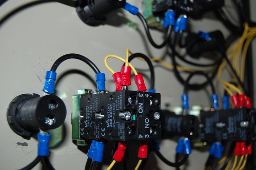
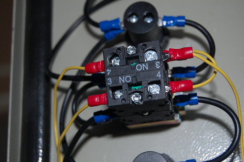
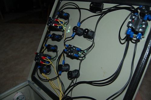
If you notice. I carry common over to pretty much all of the 110 LEDs, and just connect the dots. (pic 4 shows best) From there the Hot is connect the dots style on the switches.
Yellow is my 5v (22ga) running to the pump controls to my SSRs. All my hot comes in the bottom of the lower switches, and goes out the top. I have a common 5v hot coming into the left NO block on each switch, those share a connection. The right block is a single run to the BCS to each OUT for the pumps. I don't need this for the elements in the setup since there is no manual on, but if there was it would be wired the same as the pumps. The 2 leds at the top with small wire coming in are indicators for the 220v on, so they are separate from everything.
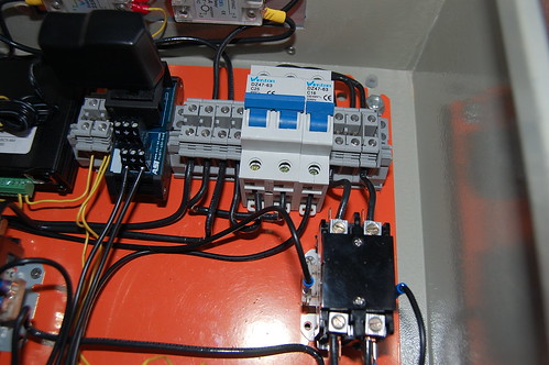

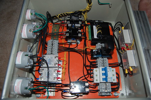
1. The power in contactor, this is what the key switch toggles on/off. That is fed into the 3 blocks, which bust the power up to distribute to the breakers and on to the panel.
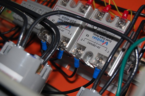
2. The SSRs mounted on the heatsink on the top. These are the SSRs for the elements only. Pump SSRs don't even break a sweat with the load.
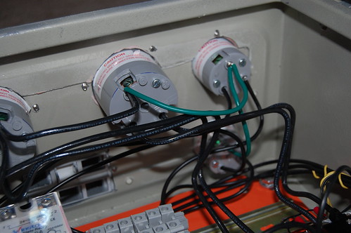
3. Bottom of panel. Top most wires, you'll notice all connect to each other, this is my ground.
4. Better look at the ground. Also, shows the L5-15FO and how small the inlets are. Its difficult to get 2 14ga wires in, not designed for it in fact. Another reason I flip the switch on the SSR and not the element directly.
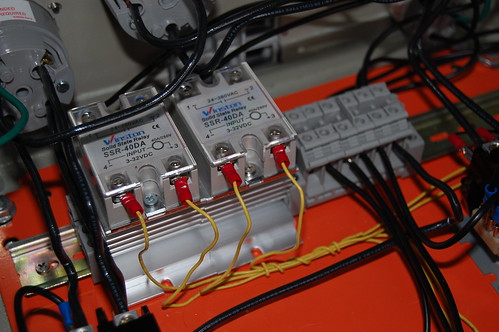
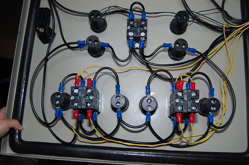
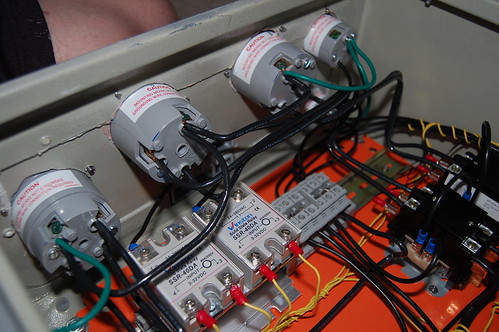
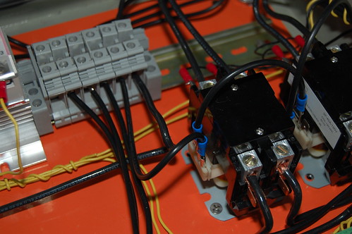
1. SSRs for the pumps from the low voltage side
2. From the high voltage side. I wired both hot wires to the DIN blocks directly. You could actually have a small jumper connecting to posts to the hot (or common) with the other post going to your outlets.
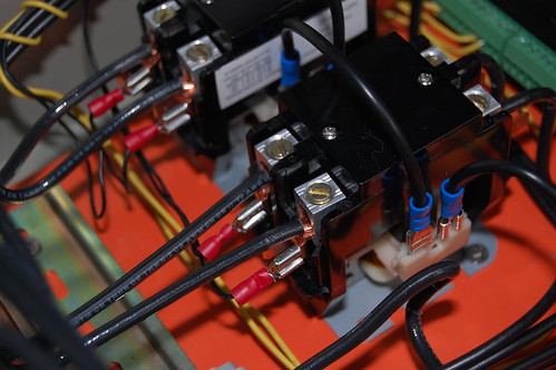
3. The contactors wired up. The red connectors are on the output side of the contactor, and wire into the LEDs on the front that show when the element is hot. If you put this on the other side, the LEDs will have a constant glow due to the leakage from the SSR, but on the out side of the contactor they stay out with the SSR is off and are bright when the SSR is on. You also can see the common being shared between the two contactors, and out of focus is the two hots coming in. 4 show the hot coming in.
Back of the door shots:
If you notice. I carry common over to pretty much all of the 110 LEDs, and just connect the dots. (pic 4 shows best) From there the Hot is connect the dots style on the switches.
Yellow is my 5v (22ga) running to the pump controls to my SSRs. All my hot comes in the bottom of the lower switches, and goes out the top. I have a common 5v hot coming into the left NO block on each switch, those share a connection. The right block is a single run to the BCS to each OUT for the pumps. I don't need this for the elements in the setup since there is no manual on, but if there was it would be wired the same as the pumps. The 2 leds at the top with small wire coming in are indicators for the 220v on, so they are separate from everything.
1. The power in contactor, this is what the key switch toggles on/off. That is fed into the 3 blocks, which bust the power up to distribute to the breakers and on to the panel.
2. The SSRs mounted on the heatsink on the top. These are the SSRs for the elements only. Pump SSRs don't even break a sweat with the load.
3. Bottom of panel. Top most wires, you'll notice all connect to each other, this is my ground.
4. Better look at the ground. Also, shows the L5-15FO and how small the inlets are. Its difficult to get 2 14ga wires in, not designed for it in fact. Another reason I flip the switch on the SSR and not the element directly.
1. SSRs for the pumps from the low voltage side
2. From the high voltage side. I wired both hot wires to the DIN blocks directly. You could actually have a small jumper connecting to posts to the hot (or common) with the other post going to your outlets.
3. The contactors wired up. The red connectors are on the output side of the contactor, and wire into the LEDs on the front that show when the element is hot. If you put this on the other side, the LEDs will have a constant glow due to the leakage from the SSR, but on the out side of the contactor they stay out with the SSR is off and are bright when the SSR is on. You also can see the common being shared between the two contactors, and out of focus is the two hots coming in. 4 show the hot coming in.
Back of the door shots:
Beeskneesbrew
Well-Known Member
I thought I had the switches figured out, but I've been second guessing myself....and now I'm sure they are not correct.
hatrickwah
Sponsor
I thought I had the switches figured out, but I've been second guessing myself....and now I'm sure they are not correct.
I'm the worst at explaining things too.
My first wire up of my setup I had individual runs for each switch going to the hot to the switches, and same for the commons on my LEDs. From there I realized I could take common runs and shorten those and share them over many. In fact, I had to buy twice as much wire as I needed because I built once. Hated the result and threw everything away and started over.
If you look at my drawings for my kits (PDFs are on the kit pages), I tried to keep one thing consistent: if the wires could be shared, I kept the lines such that it looks like one line with many branches. If it had to have its own individual path to some place, it is a lone wire.
I wish I could explain better. I may try a second round of images to help. But will have to wait until Saturday morning.
kosmokramer
Well-Known Member
yup,,, i must agree,, i think im more confused now than ever...lol thanks for the great pics and explanation hatrickwah
hatrickwah
Sponsor
I thought I had the switches figured out, but I've been second guessing myself....and now I'm sure they are not correct.
Have a pictures we can look at?
Beeskneesbrew
Well-Known Member
I'll try and get some better ones tonight.
Beeskneesbrew
Well-Known Member
How much easier would it be to wire control panel with just bcs and no manual mode?
Beeskneesbrew
Well-Known Member
Did some. Re wiring/ cleaning up! I think I now may actually grasp what is going! Bungs have now been welded too.


Beeskneesbrew
Well-Known Member
Tonight i was going through some wiring and double checking it against the diagram (which is on the first page of this post) and notice that only the switches that control the heating element have 6v going to them. Is this correct? Can someone chime in and help me understand this? Sometimes I think grasp the 3 way switch other times I dont!
Similar threads
- Replies
- 20
- Views
- 809
- Replies
- 6
- Views
- 848
- Replies
- 0
- Views
- 355
