8 ch relay connected to BCS-460

Homebrew Talk - Beer, Wine, Mead, & Cider Brewing Discussion Forum

Help Support Homebrew Talk - Beer, Wine, Mead, & Cider Brewing Discussion Forum:

This site may earn a commission from merchant affiliate links, including eBay, Amazon, and others.

BigHefty

Supporting Member
HBT Supporter
Joined
Dec 26, 2009
Messages
188
Reaction score
7
Location
Montrose, MI
I'm probably not understanding how these relays are supposed to work so forgive me in advance. See the picture below. I'm just testing mode and trying to figure out if I can use this with my BCS-460 to control my freezer for fermentation. I'm under the assumption that when the relay board gets the 5v signal from the BCS, the relay board is supposed to trigger the relay to switch to the other side. I'm trying to verify this by checking continuity at the switch. When it has no power applied I am getting continuity at the spots where it shows normally closed. However, when the 5v is received from the BCS, the switch doesn't flip. Can someone help? Do I have the understanding of this relay all wrong?
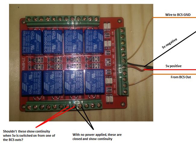
relayquestion.JPG
 
I don't know much about the bcs, but it looks like that relay wants 85mA to switch which depending on the device may be asking a lot.
 
The bcs ground should be common to the rest of the grounds. You probably need to supply power to the relay board and then the bcs can supply signal voltage to the individual relays. Also, did you check the adjacent relays to see if those were closing? Maybe there is a label that is wacky and you are testing the output of the wrong relay.
 
I don't know much about the bcs, but it looks like that relay wants 85mA to switch which depending on the device may be asking a lot.

The specs I read when I bought the board said its trigger is 3mA. Is there something in the picture that's telling you it's 85mA? If so, the BCS certainly isn't providing enough.
 
The bcs ground should be common to the rest of the grounds. You probably need to supply power to the relay board and then the bcs can supply signal voltage to the individual relays. Also, did you check the adjacent relays to see if those were closing? Maybe there is a label that is wacky and you are testing the output of the wrong relay.

The black and red wires are from an independent 5v power supply. I've checked the voltage from the BCS and it's showing 5v at the terminal on the relay board. I just don't know why it's not triggering the relay. BTW, yes, I did check all 8 of the relays when the BCS was supplying the 5v. :confused:
 
Fwiw, I'm pretty sure the 462 can provide 300ma of 5v output. Please correct me if I am wrong.

So you checked different relays on the board? Moving the signal wire around to trigger different relays? And you are pulling off the 5v output on the bcs right?
 
Fwiw, I'm pretty sure the 462 can provide 300ma of 5v output. Please correct me if I am wrong.

So you checked different relays on the board? Moving the signal wire around to trigger different relays? And you are pulling off the 5v output on the bcs right?

The BCS can supply 20mA at each 5v output.

I checked by moving the 5v output to the different trigger spots on the relay board.
 
This is an easy test: Find a wall wart that does 5v > 85mA or computer power supply and hook it up. 3 batteries in series may even work.

If it flips, it is the controller; if it doesn't, you got it hooked up wrong.
 
The specs I read when I bought the board said its trigger is 3mA. Is there something in the picture that's telling you it's 85mA? If so, the BCS certainly isn't providing enough.

I don't know about the board because I don't know anything about it.

According to the relay data sheet, which is the only part number that I can see easily, it needs something in the order of 70-90mA depending on the model. I've provided a link below for your reference.

https://www.ghielectronics.com/downloads/man/20084141716341001RelayX1.pdf

bu_gee,

Thanks much for the help and thanks for the link!! I agree that it appears to need 70-90mA. My next question is, I'm applying a separate 5v power source to the +VDC and -VDC that's rated at 850mA, what is the purpose of this power if I'm getting 5v sent from the BCS? I assumed, maybe incorrectly, that the purpose of the external power source was to assist with the input from the BCS.

Thanks again!

I'm not really sure. I found the board on AliExpress and read the description there. It appears to do isolation and I also found the 3mA figure that you stated. The other thing that I found is that the board comes in 5, 12, and 24V configurations.

Presumably the 3mA input is to operate an LED for optical isolation, but I can't find anything more about the board than that.

If you already have 5V hooked up to the board, quickly jumper the 5V positive input to one of the channel triggers and see if you hear a clicking.
 
bu_gee,

Thanks much for the help and thanks for the link!! I agree that it appears to need 70-90mA. My next question is, I'm applying a separate 5v power source to the +VDC and -VDC that's rated at 850mA, what is the purpose of this power if I'm getting 5v sent from the BCS? I assumed, maybe incorrectly, that the purpose of the external power source was to assist with the input from the BCS.

Thanks again!

The 5VDC to the board powers all the relay coils. 5VDC from BCS triggers the individual relay coils (powered by the 5VDC to the board).

Hope that was your question.

I'm using same relays in 12VDC flavor, but am not at final assembly state yet.................
 
Do you have a manual for this thing?

If I had to guess, the power from the DC+/- terminals is used to drive the relay coils (i.e., provide the 85mA or whatever it happens to be). Hence, that's why you only need 3mA for each channel. You are firing the transistor on the board which is capable of sourcing more current that the BCS. That's part of the reason you use a board like this--so that you don't have to drive the relays directly with the BCS outputs. You should make sure the power supply you are using to power the board is capable of supplying that much current though.

There are a couple ways to verify that the relay board is working:
1. Jumper the DC+ terminal to one of the input channel terminals
2. Jumper the +5VDC terminal on the BCS to one of the relay board input channels.

Though your problem could be that you aren't providing it a reference voltage at the VREF terminal. Connect the BCS +5VDC terminal to the relay board VREF terminal. This board may be designed to handle multiple signal voltage levels.
 
Ok, I'm lost. I've done the following:

1) Had 5v 850mA DC power supply hooked to +DC and -DC. Jumpered from +DC to each of the signal channels and got no response from the relays.

2) Had 5v 850mA DC power supply hooked to VREF and -DC. Jumpered from +DC to each of the signal channels and got no response from the relays.

3) Had 5v 850mA DC to VREF and -DC and 5v 1A to +DC and -DC. Jumpered from +DC to each of the signal channels and got no response from the relays.

Here's a link to the actual part at Aliexpress. http://www.aliexpress.com/item/12V-...ule-for-Arduino-RM8HLE-5V-24V/2021560245.html

I'm at a loss.


EDIT: I tried something else. Hooked the 5v from the BCS to the VREF, hooked the GND from BCS to the -DC. Hooked the Output 0 from BCS to the ch 1 on the board. Hooked 5v power supply to +DC and -DC respectively.

When I power the board, the ch 1 relay fires and is open. If I send a signal from the BCS to fire Output 0, the relay closes. It seems as if it's backwards. Does this sound right?
 
I tried something else. Hooked the 5v from the BCS to the VREF, hooked the GND from BCS to the -DC. Hooked the Output 0 from BCS to the ch 1 on the board. Hooked 5v power supply to +DC and -DC respectively.

When I power the board, the ch 1 relay fires and is open. If I send a signal from the BCS to fire Output 0, the relay closes. It seems as if it's backwards. Does this sound right?
YEAH:rockin: That's what I was getting at.

Here's an excerpt from the terrible description on their webpage :D
If VREF power anode: this port is high (compared to VREF), the corresponding relay suction
If VREF to supply cathode: this port low voltage (VREF) when relay is snap


I don't know what they mean by "suction" and "snap". Probably bad translation. But cathode is the power supply positive and anode is the power supply negative. So logically wire the BCS GND to the VREF instead.

Basically you need to have 5V between VREF and the channel you are using to fire the relay.

So are you saying I would connect the BCS GND to the VREF and the BCS +5v to the +VDC on the relay board?
 
So, could I just jumper the -VDC on the relay board to the VREF on the board and eliminate the wires from the BCS?

You can if you are still connecting the BCS GND terminal to the relay board -VDC terminal like you show in the original post.
 
Back
Top