4 wire usa gfci spa box possible to convert to 3 wire?

Homebrew Talk - Beer, Wine, Mead, & Cider Brewing Discussion Forum

Help Support Homebrew Talk - Beer, Wine, Mead, & Cider Brewing Discussion Forum:

This site may earn a commission from merchant affiliate links, including eBay, Amazon, and others.
I too have the same questions. I'm trying to build a Spa panel with a 50 amp GFCI from a 3 wire dryer outlet for portability purposes. I do own my house but move often due to the military. Attached are a few pics of my main breaker panel in my garage. It appears that it is indeed only 3 wire, the neutral is attached to the neutral bar at the main panel and is used as the ground on the outlet to the dryer plug. If I wired this up according to PJs 3 wire diagram where the neutral bar jumps to the ground bar in the panel, will I have GFCI protection regardless of being in code or not? To make matters more complicated my panel is a midwest from HD and I was hoping to add a 20 amp breaker 110v so that I can use in my garage being as all my outlets are 15 amp. I would also like to run my welder off the 50 amp GFCI. So this seems as though the neutral bar is not tied in with the ground bar at the main panel?

I hope i'm not Hijacking your thread OP, I can make this its own thread if it becomes an issue. I just would like to get a panel setup so that I can run 1 heating element, have a 20 amp 110v circuit and be able to run my welder off the 50 amp GFCI. Thanks! Excuses my horrible paint pictures
 

Attachments

  • PaintBreaker.jpg
    PaintBreaker.jpg
    60.6 KB · Views: 211
  • Paintwires.jpg
    Paintwires.jpg
    51.1 KB · Views: 124
Last edited:
Well you won’t be able to pull 50 amps off of the 30 amp breaker so that’s one problem.
 
I would just move the one neutral over to the ground bar and mark it with green tape but only if you are positive that’s the right wire.
 
So I know I won’t be able to use 50 amp off the 30 amp breaker, guess I should have just said the GFCI off the 50 amp. Is the neutral bar still somehow tied to the ground in the main panel though?
 
Maybe I’ll just run a ground from the main into the spa panel. That would give me 4 wires, guess I would just run it through conduit.
 
This does not appear to be a main panel but rather a sub panel (I don't see any breakers at the top). If it is a main panel the neutral and ground are tied together there. If it is a sub panel then they are not.

If you have HHN running to an appliance in which you have a GFCI breaker and connect the neutral to the enclosure you must make that connection on the line side of the breaker and be sure there is no connection of the neutral to the enclosure on the load side. If done otherwise the breaker will detect phase to enclosure faults and phase to ground faults but will also trip if there are any 120 V loads.

Most important: If you want to replace an existing 30A receptacle with a 50A you will have to rip out the existing #10 and replace it with #6 (this is not easy stuff to work with - it's 0.17" in diameter). Were you to pull new cable it would, of course, be 6/3 and you would install a 4 prong receptacle and be set to plug in welder, brew gear.... You would also, of course, replace the existing 30A breaker with a 50A in the subpanel. At this point you are all set. But we would ask why you would put a GFCI breaker in the brewing panel if you had a GFCI in the subpanel feeding it. Clearly a GFCI breaker in the panel is the way to go. If you want a disconnect in the brewing panel a simple breaker would do. The catch here is that while you can find a skinny 50A breaker to replace the 30A I'm not sure you can find a skinny 50A GFCI breaker. Not all is lost because you can probably make room for a GFCI breaker in the subpanel by replacing some of the other existing loads' breakers with their skinny equivalents.

Finally I have to say that the nature of your questions suggest that you should probably be relying on the advice of a professional electrician rather than some guys on the internet.
 
That would be a good option. If your receptacle is near the garage you could instead drive a ground rod through the garage floor and run a ground wire to the receptacle. Whichever is easiest or cheaper.
 
Maybe I’ll just run a ground from the main into the spa panel. That would give me 4 wires, guess I would just run it through conduit.
As I think I mentioned earlier in this thread the conduit can be your ground conductor if it is properly bonded to the sub panel and receptacle enclosure. But you'd have to pull 6/2 through the conduit for 50A. I think it would be easier to pull 6/3 (easier though perhaps not all that easy).

Running a separate ground wire adjacent to the existing cable may be sufficient. I don't know what the code says about that but I've certainly seen unprotected (no conduit) ground system wires run around installations that have passed inspection. Why would we need to insulate it? Maybe it needs to be mechanically protected.
 
I agree with ajdelange LOL. But that will be a very expensive home upgrade. I was going to do a similar upgrade to my panel but it turns out that I can’t fit a GFCI breaker in my panel and to do it to code I would have to replace my panel and move it outside because it’s in a closet and the current code no longer allows a panel to be in a closet. I decided not to do it and I just got an in-line GFCI cable.
 
Personally I would ground your receptacle and stay at 30 amps a
Even by replacing other breakers with the skinny ones?
I would have to show you my panel. My house was built in 1969 and I have a very small GE panel. I work with a master electrician and I have consulted with him for all of my plans. He said I would have to thin out one of my circuits and remove a breaker to make it fit but that kind of work would require a permit and wouldn’t be up to code. It’s also a lot more money than I would want to spend. I would rather buy a new house.
 
That would be a good option. If your receptacle is near the garage you could instead drive a ground rod through the garage floor and run a ground wire to the receptacle. Whichever is easiest or cheaper.

i'm assuming this would be to have the existing neutral function as a true neutral, with the new ground connection creating a true 4-wire (hhng) system? if so, this would be a code violation and likely wouldn't work anyway.
 
i'm assuming this would be to have the existing neutral function as a true neutral, with the new ground connection creating a true 4-wire (hhng) system? if so, this would be a code violation and likely wouldn't work anyway.
Why wouldn’t it work and how is it a code violation?
 
Well it would certainly work as an operator standing on the floor through which the new ground rod were driven would be at the same potential as that ground rod and, given that it is connected to the enclosure, at the same potential as the enclosure. As to the code violation I am not sure. Were a wire also run from the new grounding rod to the panel and tied into the house grounding system then it seems to me that it would simply be a grounding system tied to the earth at multiple places which is, AFAIK, good practice but a local inspector told me that's a no-no if the multiple grounding points are tied together with conductors that run interior to the structure. I don't know whether this is local code or in agreement with the NEC and I can see the reason for it.
 
Why wouldn’t it work and how is it a code violation?

branch/feeder circuits require an equipment grounding conductor, most often in the form of a conductor between the load and the source. this is to create a low-impedance ground path for proper operation of the upstream circuit breaker. a local ground rod without that solid connection back to the source doesn't meet this requirement. the ground conductor does not pass through the gfci circuitry and the impedance between a remote ground rod and the source breaker is such that if both line and neutral went to ground, not only would the gfci not operate but the upstream breaker wouldn't operate either. local ground rods are to help with ground equipotential planes for stray voltages or lightning strikes but do almost nothing to create 'a ground' in terms of breaker operation.

if only hot or neutral went to ground, gfci would still operate, whether the ground rod was there or not. basically, the ground rod gets you nothing.
 
That's why (fault impedance) I implied (if I did not explicitly state) that the new ground rod would have to be tied to the old system. Even then I am not sure it would meet code.

Even isolated the separate ground rod would buy shock protection but perhaps not fire protection unless the new ground rod and the rest of house ground rod had impedances less than 2 Ω each. Maybe in some soils...

it might meet code, provided that conductor from the ground rod to the source panel meets the requirements of an egc. but if going through the effort to wire back to the panel, why not scrap the ground rod entirely and make it a true 4-wire setup?
 
Ok well then I was misinformed but you could still run a ground wire from your main panel to make up the 4 wire right?
 
If he wants to go to 50A he's going to have to pull #6 in any case so, of course, if he does that he should pull 6/3 and do it right. OTOH if he is willing to stay with 30A then running a separate grounding conductor from the panel would work but does it have to run in the same cable with the phase and neutral conductors? Can it run separately and be stapled, for example, to studs in the garage? Those are questions I can't answer. I suspect at least an eyebrow would be raised by an inspector were he to do that.
 
I don’t intend on going with a 50 amp breaker, I just want to feed off of the exsisting 30 amp breaker in my garage panel which is apparently a sub panel since the main breakers are on the outside of the house near my meter. I want to run a 3 prong dryer cord 10 gauge from my dryer outlet to a spa panel which has a 50 amp GFCI. The reason this would work for me is because the sub panel in my Garage is full and all the outlets in my garage are 15amp and like I mentioned previously for portability. When We’re not using the dryer I can plug in the sub panel and do what I need. Having the sub panel setup properly with 4 wire would enable me to run a heating element so I can continue to brew beer, enable me to use my welders and possibly add another circuit off the spa panel to run a couple 20 amp breakers for power tools and whatever else in the garage. When I was in Germany I ran a 3500 watt element off my kitchen outlet 220v with an auber pid with no issues, I loved it and would like to adapt that at my new place. I appreciate the advice and replies, sorry again for the confusion!
 
I guess my question now is, would I be able to run a 10 gauge Romex ground wire from the grounding bar in my sub panel in my garage 15 ft to the spa panel to make this a 4 wire setup ? I would just run the ground wire up across the ceiling in regular plastic conduit to where I would mount my spa panel.
 
That’s exactly what I would do. I’m not an electrician though and I think it really comes down to what was said earlier about not going by what some guy on the Internet says. Hell I’m learning with everyone else and I’m trying to do the same thing but I guess if I die doing it then at least I wouldn’t have to listen to someone telling me that I was wrong :p
 
I was going to do the same thing but in my 3 wire receptacle I have 2 hots and a ground, no neutral. So I got an in-line GFCI cable and I will just not have a neutral. Hoping it works.
 
I was thinking about the in-line gfci cable and it seemed to be more expensive that route and I’m hoping with the spa panel that I’ll be able to run a few 20 amp circuits as it seems there are 2 empty spots above the 50amp gfci. Builders took the cheap route and wired every outlet in my garage 15 amps!
 
Ok so I see in the NEC 2014 it says in order to have effective ground fault current path it would have to return to the supply source and that earth shall not be considered as an effective ground fault current path. So a ground rod alone would not work. Oops....
 
So I just read the code book for an hour and a half and can’t see a reason why you can’t run a ground from the sub panel but I don’t see anything that directly mentions it. IDK it’s a big ass book.....I would think that since the sub panel is grounded to the supply and the earth through the main panel that it would be the same as using the main panel. I need a beer....LOL
 
So I just read the code book for an hour and a half and can’t see a reason why you can’t run a ground from the sub panel but I don’t see anything that directly mentions it. IDK it’s a big ass book.....I would think that since the sub panel is grounded to the supply and the earth through the main panel that it would be the same as using the main panel. I need a beer....LOL

i would say that the existing plug is considered non-grounded. 250.130(C) allows for the running of a separate ground if changing to a grounded-style receptacle. the ground can go back to the source panel and does not have to follow the path of the circuit conductors. so if it was my, i would replace the receptacle with a 4-wire, use the existing white as a neutral and install an individual #10 ground back to the panel. per 250.120(C), that ground needs to be protected from physical damage either by being armored, in raceway or within framing members.
 
Awesome thanks for all the info guys. I think this is the route I will take going forward. I see it as the surest safest way, Now it’ll be a matter of wiring the ground through the dry wall and finding the best way down to the receptacle. Do they sell insulated single 10g wiring? I’ll be heading to HD in the morning and I’ll try and post some pictures
 
Found the wire bundle for the 30amp breaker! Now the question is do I remove the old wires from the panel and fish/tape a new 10/3 bundle up to that bundle and pull through the wall to the attic, cross the attic down the attic to the opening to the receptacle in my laundry room, then simply re-wire? Or find a way to get a ground wire up to the wall through the attic to the laundry? What would you do?
 

Attachments

  • IMG_0520.jpg
    IMG_0520.jpg
    69.9 KB · Views: 44
  • IMG_0521.jpg
    IMG_0521.jpg
    62.7 KB · Views: 42
i'm always in favor of 'doing it right' so if you feel you can fish that 10/3, go for it! if accessible at enough places along the route, you could tape the new 10/3 to the existing 10/2 and pull the new in as the old goes out. if you want an insulated separate ground, they definitely sell #10 awg green single conductor wire.
 
To be honest I think that will be the easiest route, by installing new wire. I’ll figure out how to turn off power to the sub panel tomorrow. I looked at the main breaker panel and didn’t see any large size breaker for the sub panel in my garage. Maybe I’ll just turn them all off to be safe when installing the new wire
 
The sub panel has to be fed from the main panel so there must be a breaker in there. You can have a pretty hefty breaker in a pretty slim package these days and sometimes the numbers are hard to see. The easiest way to find the breaker is with a breaker tracer (plug one part into an outlet in the garage and then run the other part over the breakers in the main panel until you find the one that beeps loudest) but that represents an investment you probably won't want to make (https://www.amazon.ca/dp/B005G7SC0M/?tag=skimlinks_replacement-20). You can always turn the main panel breakers off one at a time until you find one that darkens the garage. An investment you should make is in a non contact voltage tester. After disconnecting the power for service verify that it is indeed disconnected with this little gadget (after having verified that it is working by testing it on a live outlet).
 
Last edited by a moderator:
I now have 4 wire! It wasn't as difficult as I expected, being that I had no help I kept going up and down the attic fishing the wire through. They had the wire stapled to the 2x4 going down to the laundry room outlet, I was a little frustrated but popped the staples out by wrapping the end of the old wire bundle with a pipe wrench and hammering down on it. That worked and was able to get the new wire through with no problems. I found the main breaker to the sub panel in the garage, it was a 2 pole 90 amp breaker. Killed that and the 30 amp in the sub panel. I wire everything up at the sub panel and installed the new 4 wire in the laundry room. Turned power back on and ran a load in the dryer just to ensure everything was ok. Seems everything is fine! I'll be working on the spa panel box tomorrow!!! Cheers
 

Attachments

  • IMG_0523.jpg
    IMG_0523.jpg
    76.9 KB · Views: 47
  • IMG_0525.jpg
    IMG_0525.jpg
    71.1 KB · Views: 47
  • IMG_0526.jpg
    IMG_0526.jpg
    79.1 KB · Views: 41
  • IMG_0527.jpg
    IMG_0527.jpg
    49.3 KB · Views: 42
I don't see either the non contact voltage tester or the circuit breaker tracer in the Home Despot basket. You have to understand that one of the most important parts of home brewing is collecting gadgets! But I'm delighted that the project went smoothly.
 
Your right I should have at least got the non contact voltage tester and I had every intent in doing so, I always gets so dis tracted at HD. I realized that when I got home but felt very confident finding the breaker to the sub panel in my garage and turning off the 30 amp breaker. Everything went fine, I’m confident I could re wire the 15 amp breakers in my garage if I wanted. Today I will be building my spa panel box. I’ll post pics later so you guys can critique my wiring haha!
 
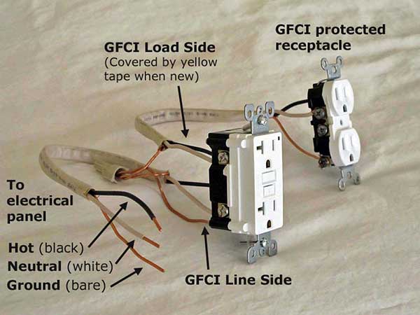
Built the panel today. I mounted the 220v socket and 20 amp gfci sockets to the panel itself. I wired everything up, the only question I had was the yellow tape across the bottom part of the 20 amp GFCI socket. I followed the terminals on top and wired the black hot to the 20 amp breaker, ground to ground bar and neutral to neutral bar. Tomorrow I will run the 10/3 romex from the laundry room through the wall to where I will mount it in my garage.
 

Attachments

  • IMG_0529.jpg
    IMG_0529.jpg
    63 KB · Views: 50
  • IMG_0533.jpg
    IMG_0533.jpg
    53.5 KB · Views: 61
  • IMG_0534.jpg
    IMG_0534.jpg
    52.3 KB · Views: 50
the yellow tape is covering the load terminals on the receptacle. these are 'downstream' of the gfci circuitry so they are gfci protected. basically, they are used if you want to continue the circuit to other receptacles so you shouldn't need to use them. those receptacles can be 'regular' receptacles but will still be gfci-protected. it is a way to save costs, as opposed to buying a gfci receptacle for all locations. if the circuit was continued off of the line terminals (the ones you used), downstream receptacles would not have gfci protection.

gfci-line-load-front-view-big.jpg
 
Back
Top