• Please visit and share your knowledge at our sister communities:
  • If you have not, please join our official Homebrewing Facebook Group!

    Homebrewing Facebook Group

Suggestions for controller

Homebrew Talk

Help Support Homebrew Talk:

This site may earn a commission from merchant affiliate links, including eBay, Amazon, and others.
Wow. Looks great.

I never realized how much influence I might have had in the mission of going electric in brewing with my diagram illustrations.

I keep researching and scheming. I think I'll quit while I'm ahead.
 
Don't quit P-J!

This was so much fun that one of these days I may do another one just for the fun of it.

Seriously, there's quite a few of us that went electric just because of your diagrams and personal help.

Adam, love those switches, can't wait to see the rest.
 
Thanks so much for your encouragement.

I wish that I had a way to post all of the diagrams and info in one place on the forum without links to my host. It would need to have the capacity to host the large images which is not possible now. I'm really concerned that all of my 'stuff' will be lost after a bit as I'm growing really old. I currently host all of my diagrams on my own personal web site. (You would not believe the number of custom diagrams I made. A lot of them have been done through PM's from fellow brewers that I tried to help.)

I fear the end. When that happens all is lost.

Sigh...
P-J
Paul
 
Well, maybe there could be a P-J diagram sticky on this forum where all your relevant diagrams could be listed? Links could be provided to builds that specifically followed one of your diagrams too. I'm not sure about size requirements, but maybe it could work. It's certainly deserving.

If you haven't yet, make sure and save them all in a hard copy form too so they're not lost.

Keep it up man, you're needed here!
:mug:
 
Yeah please don't quit PJ! We definitely need a sticky or a wiki where someone can look for the setup they want and find pictures diagrams and links to build threads.

I was just thinking about something on mine. All of my controls are on the lid which is not hinged. That's going to make it hard to open it up and set the list somewhere safe. Would it be possible to create a wire harness so I can remove the lid? Anyone have any experience with something like this? Is it hard to do?
 
I was just thinking about something on mine. All of my controls are on the lid which is not hinged. That's going to make it hard to open it up and set the list somewhere safe. Would it be possible to create a wire harness so I can remove the lid? Anyone have any experience with something like this? Is it hard to do?

Can you just hinge the lid? I did something similar with mine and it was very easy to do. I actually hinged a plate that's under my lid, but it's the same idea.

IMG_5439s.jpg
 
Kevink, I suppose I could give that a try. How did you get your wires to lay like that? Did you glue them?
 
Thanks, Thunder etc.!

Adamcanfly,
No glue. I bent the wires into the shapes they needed to be and only rely on the ring terminals to hold them in place. I also used four cable tie mounting bases for the wires that go from the control panel chassis to the top plate. You can just make out two of them on the right side of the photo.
 
So I see JS guitar reccomends westmarine bus bars. But P-J's diagram calls for 4 terminal strips. What/where is the correct part for the job?
 
So I see JS guitar reccomends westmarine bus bars. But P-J's diagram calls for 4 terminal strips. What/where is the correct part for the job?

I show images of terminal strips so that the person building the unit will use that idea instead of splicing wires and using wire nuts. (Bad idea.)

It is the builders call on the choice of the strips available and rated for the particular task at hand.
 
I got it dialed in it seems. I guess I just didn't know what I was doing before. I have the Pb set to 3 and it seems dead on now. I set t to 2 if I remember right and hyst to 2. I initially set P to 1 based on some reading here but I ran an autotune and it set it to 80.

I tested both outlets with my hlt since I need to replace the element in th BK and replace both sight glasses. Both element outlets worked perfectly

It held 150 in automatic mode and boiled in manual mode without a hitch. I took some pics. My location's boiling temperature is around 210.4 degrees, so at the moment the sensor is reading between 210-211 (switching between them). I may fine tune the Pb setting a bit more later if needed.

It boils just like I expected. I think it took around ten minutes to boil from 150 degrees.

Pic 1: plugged in to the HLT outlet
Pic 2: holding at 150
Pic 3: boiling in manual mode
Pic 4: BK outlet
Pic 5: Boiling! No pulsing. Just a nice steady boil.

Now I just need to prepare my brewing area and I'm in business!

Your panel looks great, but I can't seem to find a picture of the inside of your build. Would you mind posting some pictures of the inside finished wiring and so forth? Also, did P-J or yourself ever build one with the push button switches detailed in the original wiring diagram? Lastly, how could I adapt this build to control my RIMS tube for my single tier propane rig? The only electric component in my brewery at this point will be the RIMS tube as I don't have the desire to go electric, yet. Thanks for the help in advance.
 
Your panel looks great, but I can't seem to find a picture of the inside of your build. Would you mind posting some pictures of the inside finished wiring and so forth? Also, did P-J or yourself ever build one with the push button switches detailed in the original wiring diagram? Lastly, how could I adapt this build to control my RIMS tube for my single tier propane rig? The only electric component in my brewery at this point will be the RIMS tube as I don't have the desire to go electric, yet. Thanks for the help in advance.

Thanks for your comments. Here's some pics of the inside: (it's built directly from the 1st diagram at the top of p.3)

https://www.homebrewtalk.com/f170/suggestions-controller-249400/index4.html

The pushbutton switches are an easy change to make and Adamcanfly is doing just that (as he showed a page back or so in this thread). There are also some more recent similar builds that are using those switches.

To your last question, I'll defer to P-J on that one. There's a bit more info needed to determine what your needs are for that.

:mug:
 
...
Lastly, how could I adapt this build to control my RIMS tube for my single tier propane rig? The only electric component in my brewery at this point will be the RIMS tube as I don't have the desire to go electric, yet. ...
It can be done - but - you are entering a whole new ball game with that plan. Controlling the output temp of a RIMS setup is really dependent on precisely measuring the output temp - which in turn is dependent on the flow rate and the placement of the temp probe and the probe type. Any changes in any factor will dramatically effect the results. Good luck with that. And if you go that route, please let us know what you did.

IMHO, a better and more easily controllable setup would be to use a HLT with a heat exchanger to accomplish the task. Temp control is easy.
 
So I finally finished the spa panel and went to plug in my control box for the first time and am having some problems. Right when I plug in the box it pops the GFCI.

I used the attached diagram but made a few changes. I used this one because I wanted two LED's but I didnt need the timer. It's wired exactly like this minus the timer and it's connections.

Let me know if this is the proper way to do this or if something else should be changed when removing that item from the diagram.

If that's correct let me know if you have any other specific suggestions to check. I haven't had time to check anything yet but just wanted to get feedback on this first. Tonight I should have time to open it up and double check all the connections.

Control Panel -Auberin-wiring1-a17b-SYL-2352-5500w.jpg
 
So I finally finished the spa panel and went to plug in my control box for the first time and am having some problems. Right when I plug in the box it pops the GFCI.

I used the attached diagram but made a few changes. I used this one because I wanted two LED's but I didnt need the timer. It's wired exactly like this minus the timer and it's connections.

Let me know if this is the proper way to do this or if something else should be changed when removing that item from the diagram.

If that's correct let me know if you have any other specific suggestions to check. I haven't had time to check anything yet but just wanted to get feedback on this first. Tonight I should have time to open it up and double check all the connections.
First thing to try is to pull the fuse going to the E-Stop switch and try again. That will tell you if it is wired correctly. If the breaker still trips you need to look at how you have wired the neutral output of the GFCI breaker. The neutral must be from the breaker its self for the output to your controller.

Please let me know. I'll try to help you in any way that I can.

P-J
 
Thanks P-J. I will give this a shot when I get home tonight and let you know if I'm still having any issues.
 
So I took the e-stop fuse out and it worked without popping the GFCI.

I unplugged the box and opened it open and took a few readings with my multimeter. I checked the e-stop and noticed I was getting continuity when the button was unpressed but not when it was pressed.

Turns out I ordered GX3135 instead of GX3139. I did this because I liked the red button instead of the yellow but the contact block that came with mine is Normally Closed(N.C.). I guess I will be ordering one of the green contact blocks which will fix this problem.

I was really hoping to try this out on Sunday but now I have to wait for the new contact block. Would it be safe to clamp down the button or something and use it like that or should I just wait for the new part?
 
You are welcome. It is my pleasure.

(BTW: Now you discovered why I chose the GCX3139 push button. It's the only one I found that came with a N/O contact.)

Another thought: If you want a modified diagram showing the plan without the timer, I can do that for you.

Wishing you the best.

P-J
 
Well I got the element and temp probe installed in one of my kegs last night so I decided to fire it up! Within a few minutes I had configured the important settings on the PID and had it running in both manual and auto mode.

After about 15 minutes in auto I decided to turn it off and move the kettle plug from the HLT outlet to the BK outlet to test it since my second kettle wasn't done yet. After doing this I plugged the box back in and flipped on the PID which came right on. When I flipped the switch to the BK element the GFCI popped after a few seconds. I reset everything and tried again but same result. At this point I figured there was something wrong with the wiring of the BK circuit so I turned it all off and moved the element plug back to the HLT outlet. After this the PID came on but when I flipped the switch to the HLT element it also popped the GFCI. I turned everything off and tried a few more times with the same outcome.

Since the system was running fine on the HLT setting and then stopped after I switched to the BK the only thing I can think of was something came loose inside while I was shuffling the box around changing the connections.

By this point it was pretty late so I decided to call it a night. It was awesome to see it finally working but a little frustrating to have the issues at the end.

Tonight I will open the box again and check all the connections again. Let me know if you have any specific suggestions of things I should check.

Control Box_First power on-20110921.jpg


Wiring First Element-20110921.jpg


Element test 1-20110921.jpg


Brewery almost complete-20110921.jpg
 
I have a question for P-J going all the way back to the diagram on page one.

I showed the diagram to my father-in-law, an electrician, and he was concerned that you're using a DPDT switch that is only rated for 15A on a 240 circuit. Shouldn't we all be using a switch rated at 30A for a 5500 watt element?
 
I just finished up my first batch using the new electric setup. I had a few problems but overall it went very well.

The biggest issue I had was the same issue I posted about a few days ago. Basically when using my HLT it is blowing the GFCI. Once I got the BK complete I was able to do some further testing and the problem seems isolated to the HLT. When using the BK I have not had the problem once. I have used the BK in both outlets on the control box without the issue. I have also switched the power cable from the HLT to the control box with the one on the BK and that didn't fix it so I know it's not a problem with the cable/plug.

The only thing I haven't switched is the element. The only thing that I can think is happening is a very small amount of water is getting past the seal on the kettle and causing the GFCI to pop. I had a little trouble getting the element into the HLT because it was hitting my pickup tube so I did have to make the hole slightly larger than the one one the BK. It is barely larger though, just a couple more passes with a grinding attachment on the dremel tool. I have not seen any visible sign of water leaking but cannot think of what else may be causing this.

My plan to fix this is to get some high temp food grade silicone and put it around the threads on the element. If this doesn't fix it the only other thing I can think to do is replace the element but that seems unlikely to be causing this issue.

Let me know if anyone has any other suggestions that might fix this.

So despite that problem I was still able to have a successful brew day. I had to juggle some water back and forth from the BK to the HLT during the sparge but it worked out.

Here are a few pictures of my finished steam hood. I still need to mount the pump and CFC and make a few minor tweaks but at least its functional! :mug:

Hood closeup-20110924.jpg


Hood Inside-20110924.jpg


Brewery 1st run-20110924.jpg
 
...
Basically when using my HLT it is blowing the GFCI. Once I got the BK complete I was able to do some further testing and the problem seems isolated to the HLT.
...
The only thing I haven't switched is the element. The only thing that I can think is happening is a very small amount of water is getting past the seal on the kettle and causing the GFCI to pop. I had a little trouble getting the element into the HLT because it was hitting my pickup tube so I did have to make the hole slightly larger than the one one the BK. It is barely larger though, just a couple more passes with a grinding attachment on the dremel tool. I have not seen any visible sign of water leaking but cannot think of what else may be causing this.

My plan to fix this is to get some high temp food grade silicone and put it around the threads on the element. If this doesn't fix it the only other thing I can think to do is replace the element but that seems unlikely to be causing this issue.
...
Great diagnostics. Well done.
IMHO - Yea you have a leak past the element seal. (First brush with the issue) It seams that the O-ring on the outside of the kettle is not giving you a total seal. Please try this: Take the element out so that all of the threads are exposed. Then wrap several layers of Teflon plumbers tape around the threads. Re assemble and try again. Last resort? Replace the element to eliminate an element defect.

geeze - I'm puzzled as well.
 
Thanks for your comments. Here's some pics of the inside: (it's built directly from the 1st diagram at the top of p.3)

https://www.homebrewtalk.com/f170/suggestions-controller-249400/index4.html

The pushbutton switches are an easy change to make and Adamcanfly is doing just that (as he showed a page back or so in this thread). There are also some more recent similar builds that are using those switches.

To your last question, I'll defer to P-J on that one. There's a bit more info needed to determine what your needs are for that.

:mug:
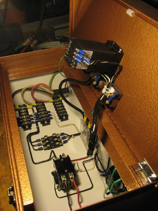
Thanks for the response. It's probably me overlooking them, but the link you posted here just links back to the original thread, which I can't find any pics of the inside of your controller. Any chance you have some or can take some? Thanks.
 
Back
Top