• Please visit and share your knowledge at our sister communities:
  • If you have not, please join our official Homebrewing Facebook Group!

    Homebrewing Facebook Group

Suggestions for controller

Homebrew Talk

Help Support Homebrew Talk:

This site may earn a commission from merchant affiliate links, including eBay, Amazon, and others.
It can be done - but - you are entering a whole new ball game with that plan. Controlling the output temp of a RIMS setup is really dependent on precisely measuring the output temp - which in turn is dependent on the flow rate and the placement of the temp probe and the probe type. Any changes in any factor will dramatically effect the results. Good luck with that. And if you go that route, please let us know what you did.

IMHO, a better and more easily controllable setup would be to use a HLT with a heat exchanger to accomplish the task. Temp control is easy.

Thanks, P-J. I didn't realize I was entering new territory incorpating a RIMS tube. Not saying I'll never go HERMS, and considering what I have already built and bought, I think I'm going to stay the course with my RIMS tube and not switch to HERMS, but I could still use some help from the "experts". I've seen some threads where you've helped some others incorporate RIMS in their controller setups, so I was hoping you could help me simplify things. I've already built the RIMS tube and my direct fire keggles. The controller is the only missing link. My controller should take a much simpler design than an all electric rig. The only electric component I need to control is the RIMS tube, which has the following components. I'd like to run it at full flow to maximize the amount of whirlpool I can create in my mash tun, so restricting flow was not something I planned on doing. The temp probe is located in the outlet end of the RIMS tube.

Liquid tight 4" type K thermocouple 1/2" NPT - Auber TC-K100M1/2NPT
120V 1500W Low Density Heating Element - Grainger 2E295
Pump - March 809HS

Here's the other stuff I planned on buying thus far.

PID - Auber SYL-2352
40A SSR - Auber RS1A40D40
Heat sink - Auber HS40
Enclosure - Auber Pbox16
Switches - Pilot Automotive PL-SW26 (Kind of TopGun'ish)

I'm certainly open for suggestion and looking for help planning and wiring things up. You probably thought I'd never ask, but would you be willing to help me with one of those famous diagrams of yours? Thanks, man.
 
If you scroll down the page that I linked it shows the inside. The link works for me, but if it doesn't work for you again then just go to page 4 and scroll down the whole page a little and read the descriptions. I'm not sure you'll gain much from looking at the inside though because you really can't see very much clearly due to all of the wiring being tightly packed in there and it also looks like you're building something entirely different.

Hope this helps.
 
...
I've already built the RIMS tube and my direct fire keggles. The controller is the only missing link.
...
I'm certainly open for suggestion and looking for help planning and wiring things up. You probably thought I'd never ask, but would you be willing to help me with one of those famous diagrams of yours?

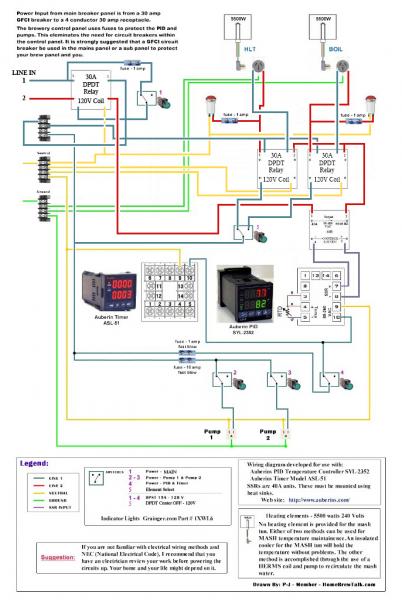
As always - Click on the image for a full scale diagram printable on Tabloid paper (11" x 17"):

 
As always - Click on the image for a full scale diagram printable on Tabloid paper (11" x 17"):


Your diagram really helps a lot, P-J. Where would we be without you?

A couple questions...

1. My RIMS element is a 120V 1500W Low Density Heating Element - Grainger 2E295. That being the case, could I stick with a 15A switch since the load should only be 12.5A for a 1500W element in lieu of 16.7A for a 2000W element?

2. Switch 1 and 2 are called out DPST and Switch 3 is shown to be SPST. Is it possible to wire it in a way to use all SPST switches? I had hoped to use these switches on the panel which are Pilot Automotive PL-SW26R, which can be seen at http://www.pilotautomotive.com/Product.aspx?ProductID=27308&PCID=1068. I'm pretty sure these are not DPST switches or maybe I need to find a new manufacturer that offers the cool top gun switches with more configuration choices.

3. My original plan was to use a liquid tight 4" type K thermocouple 1/2" NPT - Auber TC-K100M1/2NPT. Your diagram shows an RTD. What changes in the wiring if I use the thermocouple? Would I be better off using an RTD?

Thanks, again. I'm excited to get everything ordered this weekend.
 
zacc, your setup is looking great. Love the exhaust hood. Did you figure out the electrical problems yet?

I haven't had much time lately but I got my pumps installed in my SS table and found some lint trap quick connects to make my dryer exhaust swap easier which works great so I'm not going to do a dedicated exhaust after all. Hopefully I'll update with pics when I'm not feeling lazy.

Adam, any progress?
 
zacc, your setup is looking great. Love the exhaust hood. Did you figure out the electrical problems yet?

Well I think the problem is possibly a small leak in the seal of the element to the kettle. I wrapped the thread with Teflon tape and also used some high temp food grade silicon. I haven't had a chance to test it yet but should have time tomorrow to give it a shot. If it still doesn't work properly the only thing it could be is a faulty element.

This past weekend I scored a free garage door opener from someone on craigslist. I guess there was something wrong with the control board but I just needed the motor. I mounted my grainmill on an old gorilla self and am using the motor from the garage door opener with a few pulleys to power it. I just tested about a pound of grain through it so far but it seems to work great. I'm not exactly sure what RPM's I'm getting but I estimate its around 150, it seems perfect for the mill. This gives a much nicer crush than I get with a drill running at high RPM's, plus I can just fill it up and turn on while doing something else instead of sitting there holding a drill.

I'm going to be heading out of town for a few weeks but once I get back I plan on doing some serious brewing. I'm way behind on my brewing due to all the time spent on this new setup. My wife has been bugging me to brew my pumpkin ale so that will probably be my next batch.
 
I've been following this thread intently. I've been thinking of going electric and I think this control panel would really work out well for me. I would like to start with a basic system using my current 70quart cooler mash tun and a heating element in my BK and HLT- controlled with one PID and using one to two pumps. I currently have a 50 amp 240V breaker installed in my home fuse box. (It was used for a hot tub that was taken out before we moved in). The wiring was pulled, but the breaker is still there. I am guessing I could run conduit off of this for the control panel? I called a local electrician and was quoted a seemingly high amount of about $200 just to run the wire an install a 4 prong box. Is this that hard to do? Would appreciate any advice.
 
I've been following this thread intently. I've been thinking of going electric and I think this control panel would really work out well for me. I would like to start with a basic system using my current 70quart cooler mash tun and a heating element in my BK and HLT- controlled with one PID and using one to two pumps. I currently have a 50 amp 240V breaker installed in my home fuse box. (It was used for a hot tub that was taken out before we moved in). The wiring was pulled, but the breaker is still there. I am guessing I could run conduit off of this for the control panel? I called a local electrician and was quoted a seemingly high amount of about $200 just to run the wire an install a 4 prong box. Is this that hard to do? Would appreciate any advice.

It sounds like your looking for something similar to what I was looking for when I found this build. I only have one batch on my system but I already love it.

As far as the electrical is concerned I would recommend getting help from someone with experience. Running a new circuit off the breaker isn't really hard but it can be extremely dangerous.

Your going to want to a 30 amp breaker for the control box and you should definitely have a gfci. You can either get a breaker with a built in gfci or just get a 30amp breaker and then use a spa panel with a built in gfci like a lot of us on this forum use. When i was pricing these the straight 30amp gfci was pretty easy to find and cost around $10-$20. I only found the 30 amp breaker with the gfci online and it was nearly $100, this is why I went with the spa panel.

Anyways to sum up unless your confident that you know what your doing or have an experienced friend to help I would hire an electrician to wire the outlet for you. Have a 30 amp breaker installed at the same time and your all set.
 
After adding the teflon tape and silicon to the element seal my problem kettle seems to be working better but still isn't perfect. After running for about 45 minutes today it popped the gfci.

When I reset it and tried to turn it back on it immediately popped it again. Next I pulled the cover off of the box around the element to see if there were any signs of moisture, which there werent. Not only did i put silicon around the threads but once the element was tight I filled the area around the base of the element with silicone.

After I checked the seals and waited a few more minutes I turned the element back on. I let it run for about an hour and half longer set at 165 in auto mode without any further problems.

Although the test was a lot better than my previous results I'm still not 100% confident in my HLT. I'll try it again next brew day and if the problem returns I will order another element.
 
Thanks zacc for the info. I’m not overly confident in my electrical knowledge so I guess I’ll bite the bullet and hire an electrician to install the breaker for me. Just so I’m understanding correctly- What I need to do is install a basic 30amp 240V non GFCI (3-wire) breaker in my main fuse box (like this -http://www.amazon.com/CRO-MP230-CIRCUIT-BREAKER-MURRAY/dp/B004XZOBOY). From here I would have this breaker hardwired into the GFCI spa panel (4-wire). Do I connect the 4-line wire leaving the spa panel to a 4-prong outlet box that the controller will plug into? Or is this just typically just hardwired into the control box?
 
Last edited by a moderator:
Thanks zacc for the info. I’m not overly confident in my electrical knowledge so I guess I’ll bite the bullet and hire an electrician to install the breaker for me. Just so I’m understanding correctly- What I need to do is install a basic 30amp 240V non GFCI (3-wire) breaker in my main fuse box (like this -http://www.amazon.com/CRO-MP230-CIRCUIT-BREAKER-MURRAY/dp/B004XZOBOY). From here I would have this breaker hardwired into the GFCI spa panel (4-wire). Do I connect the 4-line wire leaving the spa panel to a 4-prong outlet box that the controller will plug into? Or is this just typically just hardwired into the control box?

Hi sredz, sorry I didnt respond earlier, I've been out of town.

You could either hardwire it our use plugs. If your running a new line I would recommend wiring that to a 4 wire outlet. Then depending on wether you used a breaker w/GFCI you would either plug the spa panel into that outlet or the control box. If using the spa panel it should then have a 4 wire outlet for you to plug the control box into.

If your looking to make it easier for yourself i would recommend just using the breaker w/gfci. Since your going to be running a new line anyways going this route is only like $20-$30 more than using the spa panel. This way once the electrician installed the new circuit you would just plug your box in and not have to do anything else.
 
Last edited by a moderator:
I'm getting ready to start a control panel build. I liked the single PID, 2 element design used here, but wanted to make a couple of changes. I'm more comfortable with a main power on/off, rather than the e-stop. And, I prefer to use contactors rather than the 3PDT switch concept. So, I started with PJs drawing, and made a few changes. I'd appreciate any comments/suggestions/concerns a more experienced eye might have.

Thanks

EPC control panel drawing.jpg
 
It's been a while since I last posted so I just wanted to give an update. I replaced the element in the kettle that was giving me problems and it has worked perfectly since then!

I have brewed 6 batches so far on this system and absolutly love it! Thanks for all the help jsguitar and P-J! :mug:

For anyone on the border about electric I would highly recommend it!
 
As always - Click on the image for a full scale diagram printable on Tabloid paper (11" x 17"):


I'm working my way towards a RIMS system. After finally getting my dinky pid controller functioning I've become much more confident in how these things work. I do have a few questions about this diagram.
What is the part that says zero voltage circuit? Can I replace it with a SSR(since I already have one available)?
And I'm sure it can but I need to be reaffirmed, with the 2000w element running, the pump can also be running(assuming its a march 809)?
Also, I found the mouser 25a switch. But that site is overwhelming. Can I get a part number/link to the DPST 15A 120v switch and the SPST 15A 120v switch
 
Hi All...I've been following this post for a few days and I am looking to build something along the lines of this diagram. Can someone explain to me why the heating elements only need 3 prongs, and don't have a neutral wire coming out of them like everything else? Does the ground act the same as the neutral for these?

Also, I'd be interested in learning how the yellow EPO works. Do any of these panels have an on/off switch, or is this the only thing? Am I correct that it relies on tripping the GFCI to turn the panel off?

In Kal's plans he has the box grounded as well...I don't see this on any of these diagrams. And do any of these show how to wire in a temp probe to the HLT?

Sorry for all the questions.

Thanks!

Jim
 
smoothlarryhughes said:
Hi All...I've been following this post for a few days and I am looking to build something along the lines of this diagram. Can someone explain to me why the heating elements only need 3 prongs, and don't have a neutral wire coming out of them like everything else? Does the ground act the same as the neutral for these?

Also, I'd be interested in learning how the yellow EPO works. Do any of these panels have an on/off switch, or is this the only thing? Am I correct that it relies on tripping the GFCI to turn the panel off?

In Kal's plans he has the box grounded as well...I don't see this on any of these diagrams. And do any of these show how to wire in a temp probe to the HLT?

Sorry for all the questions.

Thanks!

Jim

Although I built this box I'm not an electrician and can't tell you exactly why it doesn't need a neutral. I know it needs the two hot lines to get the 220 but not sure on the exacts beyond that.

The resistor inline with the epo switch causes a small current leakage which in term pops the gfci. This is meant just as a quick emergency off switch, I have never used it on mine except for testing. There is a power switch for each component on the box so just turn all of those off and your good.

The ground terminal may not show it in the diagram but it should be a grounding post so the box is grounded. All of the diagrams should include the temp probe otherwise the pid could only be used in manual mode.

Hope this helps a bit.
 
so how do these systems work? temperature probe is hooked up to HLT or MT to use PID to control temp during mashing. but how does the boil work? are the temperature probes interchangable? like quick disconnects once mash is over you disconnect temp prob and hook it up to boil kettle? sorry for the newb questions but I'm trying to convert my virgin kegs and would like for this type of system to be in the not so distant future so i want to have all my bases covered when i start ordering all of my bulkheads, valves, sight glasses, eetc...
 
Hi forcabrew,

Re: the boil, this diagram/diagrams uses the Auber 2352 PID which has a manual mode with a dedicated button (A/M) to easily switch between auto and manual modes. Mine is based on the first diagram on p.3. I've got one probe in the HLT and when it comes time to boil I switch the power output to the BK heating element and hit the A/M button on the PID to switch to manual mode. The PID requires a probe hooked up regardless of mode, but in manual mode it doesnt rely on that input but instead delivers power based on whatever percentage you set it to. So your one probe can stay in your HLT AND you can use the same PID in manual mode to control the BK.
 
P-J,

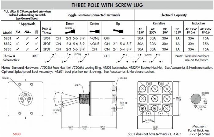
As per my pm, I've been working on switching out my selector switch from the NKK S-33F to a NKK S833 high capacity switch. Firstly, this has been amazingly challenging. The stranded wire will not fit no matter what I do so I finally just used crimp connectors. I have a good double ratchet crimper so I'm not too worried about that.

The problem is now the panel doesn't appear to be getting power. The PID switch won't illuminate when turned on and the element indicator light won't come on. Are the switches to be wired the same? They look like it but maybe I screwed something up.

Thanks for any help.

BTW, the wiring diagram I used is on the top of page three of this thread.
 
jsguitar,

Here is the data sheet for that switch (NKK S833). Sounds like you might have a wiring error. Please check the sheet + your wiring and let me know.

P-J

S833.jpg
 
Ok thanks. Hmm, I looked at sheets for both switches and it looked like they operated the same, no? Maybe I'm missing something.

The other thing that I can't figure out though is why the PID won't come on suddenly. There appears to be power at the unit and the switch seems to be working but the PID doesn't turn on. Im thinking there may be an issue with the neutral all of sudden but I can't seem to find where. I did take the PID out to get the switch in but I just double checked that again.


Oh well, I probably pick it up in the morning and check the whole thing over carefully.
 
Suggestion: Unplug the panel (for sure) and then use an ohm meter to trace your neutral wiring and all of the connections in that path. It sounds like the neutral is open somewhere within the panel.

If not: The next step is to measure the voltage at the outlet where you plug your panel in. If the neutral is open somewhere these 2 techniques should help you find the problem.

Wishing you success and great luck. If we need to talk this through, Please let me know and we'll do it. Ok?

P-J
 
That's great PJ, I appreciate your help. I've got a cold today and have been working hard on this thing, so I think my brain is just shot right now. I'll follow your suggestion and let you know how it's going tomorrow.

Thanks again.
 
Ok thanks. Hmm, I looked at sheets for both switches and it looked like they operated the same, no? Maybe I'm missing something.
I just caught that. I researched the current switch and put together the pertinent info from that data sheet today. I didn't bother researching the previous one. (It's history after all) so I figured???

Oh well... Ok, now on to the new plan.

Paul
 
Got it! Errr, I mean fixed a dumb mistake.

When I was trying to wire the new (huge) switch, I ended up removing some wires that were in the way. What happened was, I unhooked the indicator light's neutral connection. I later hooked that up to the black hot because it was a black wire and I wasn't thinking. By doing that, I left the neutral screw/jumper undone that connected all of the other neutral lines in the panel to the main neutral. So, I hooked it back up to the right spot and all is working! Another stupid mistake remedied!

Thanks PJ for your time!


ETA: Also, I actually moved a hot wire into a spot that I didn't have jumpered as well. I got that moved too. Hopefully no more surprises.
 
Got it! Errr, I mean fixed a dumb mistake.

When I was trying to wire the new (huge) switch, I ended up removing some wires that were in the way. What happened was, I unhooked the indicator light's neutral connection. I later hooked that up to the black hot because it was a black wire and I wasn't thinking. By doing that, I left the neutral screw/jumper undone that connected all of the other neutral lines in the panel to the main neutral. So, I hooked it back up to the right spot and all is working! Another stupid mistake remedied!

Thanks PJ for your time!
You are more than welcome.

Ok... Now>
I unhooked the indicator light's neutral connection. I later hooked that up to the black hot because it was a black wire and I wasn't thinking.
Now you know why color coding the wire is so very important.

I suggest that you replace that chunk of wire to white (the proper color) now. This way you don't run into problems down the road when the overall plan cannot be pulled back from memory. (Hey... I can relate as my memory about 'stuff' sucks now at my point in life. [73 now] Just saying.)

I'm really glad you got the problem solved. That is what matters.

Wishing you the very best.!!!

Paul
 
Thanks PJ. It would be nice if the indicator light actually came that way. It's prewired and both wires coming out of it are black. I can put some white tape on it for sure though so I don't make that mistake again.


Cheers
 
So I swapped out my selector switch. Had a brew day last weekend and everything went well with the controller. Even though after a year of brewing with this system I have had no problems with the switch, I though I'd be extra safe and swap it out with a much beefier one. If I had to do it over again I would have done the DPDT switch and two element indicator lights, but since I already had everything configured for the 3PDT switch, I stayed with that design.

Thanks again to P-J for his wiring diagram, good advice, and willingness to help. Also thanks to P-J and other members for keeping everyone safe.
 
Coffee station when not brewing (beer that is)

storage.jpg


brewspot.jpg

set up on table

set up.jpg

Vent hung with strap on water pipe (it's very light and moveable this way)

vent stored.jpg

vent fan

vent fan.jpg
 

Latest posts

Back
Top