The CAD thread

Homebrew Talk - Beer, Wine, Mead, & Cider Brewing Discussion Forum

Help Support Homebrew Talk - Beer, Wine, Mead, & Cider Brewing Discussion Forum:

This site may earn a commission from merchant affiliate links, including eBay, Amazon, and others.
Is that so, Uncle Rico? :D

I have got to watch that again!

Our office is right by the beach, Niagra is too far. But if I fling it just right I could probably knock out a surfer too :D. I was browsing HBT while waiting for my computer to etransmit all the files :D :tank:

Yeah, I'm up in Orange County. Maybe the Santa Ana River is more realistic. It might actually have some water in it today.
 
I have got to watch that again!


Yeah, I'm up in Orange County. Maybe the Santa Ana River is more realistic. It might actually have some water in it today.

I have a choice between the Atlantic Ocean and the Intracoastal Waterway. Salt or Brackish?
 
CAD dude here too! Use AutoCAD a lot, but 90% Solidworks. Can't live without that z-axis :D

And don't say AutoCAD 3D. :goat:
 
Ugh....hatching.

I once had a drawing that would crash every time I tried to add hatching. Eventually, I had to make a separate drawing with just the boundaries and hatching and then xref that in. But if I recall correctly (it's been a while) if you turn off and freeze all the layers that do not pertain to your boundary and hatching, the crash rate goes WAY down.
 
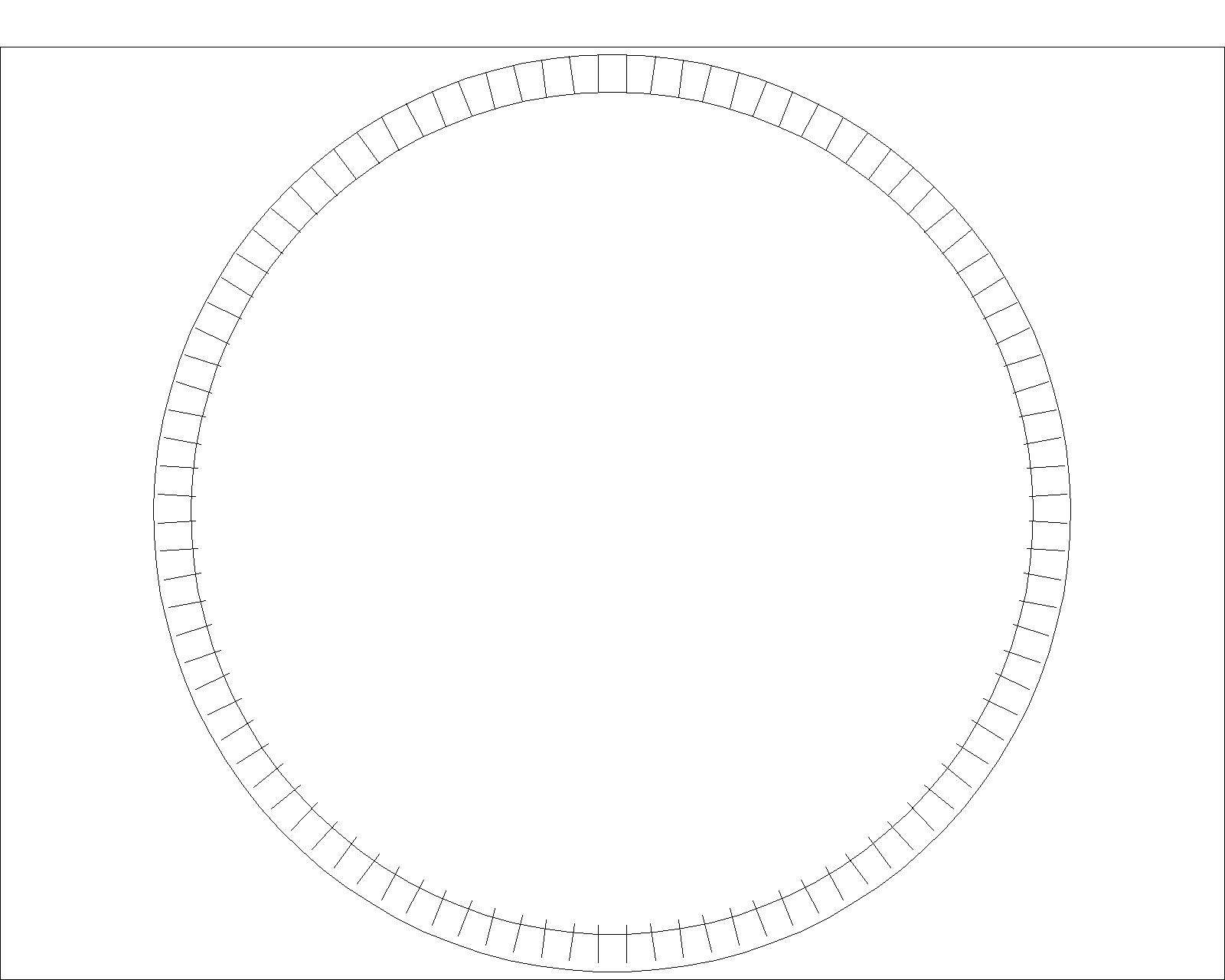
I could use some assistance guys. I'm working on an assignment where I have to draw a sprocket.

I'l try to explain as best as I can:
So far I have a 12.25 diameter circle and then I have an 11.25 diameter circle inside of the larger circle. The larger circle is for the sprocket teeth. I drew one line from the center point up and then offset it to .1875 on each side. I trimmed it to fit inside of the circles. I then created a polar array, and set my items to 50. From this point on, my plan was to use trim and that would complete my sprocket teeth and I could move forward. Whenever I create my polar array, I end up with this (see attached picture) What am I doing wrong? I tried extending the lines instead of trimming them before creating my array, and then my plan was to trim from there but it won't allow me to do that :/ Any help is greatly appreciated.

Sprocket-Problem1.jpg
 
I could use some assistance guys. I'm working on an assignment where I have to draw a sprocket.

snip...

that's an easy one. just to be certain,
  1. delete all of the lines and the outer circle, leave the inner circle.
  2. offset the inner circle out by the depth of the teeth.
  3. use the QUAD Osnap to draw a line from the 12 o'clock position of the inner circle to the 12 o'clock position of the outer circle.
  4. using the array command enter the number of elements in your final array.
  5. for origin, make sure you use the "center" osnap and pick one of the circles.
  6. proceed as before.

you didn't select the center of the circle as your origin, that's what messed up the array. It's possible that the two circles weren't concentric, but they look ok. it's also possible that the line wasn't properly aligned, but that also looks ok.
 
... I drew one line from the center point up and then offset it to .1875 on each side. I trimmed it to fit inside of the circles. I then created a polar array,....

I just reread your post. the problem was with the offset lines. they were no longer radial.

you drew a line from the center of the circle. so far, so good, Then you offset that line, that's bad. you ended up with three lines that are parallel to each other. what you wanted was three lines that had the same origin (center of circle) and extended out to a point perpendicular to the outer circle.

I hope that makes sense. you should have stopped after trimming the first line, and arrayed it.
 
I could use some assistance guys. I'm working on an assignment where I have to draw a sprocket.

I'l try to explain as best as I can:
So far I have a 12.25 diameter circle and then I have an 11.25 diameter circle inside of the larger circle. The larger circle is for the sprocket teeth. I drew one line from the center point up and then offset it to .1875 on each side. I trimmed it to fit inside of the circles. I then created a polar array, and set my items to 50. From this point on, my plan was to use trim and that would complete my sprocket teeth and I could move forward. Whenever I create my polar array, I end up with this (see attached picture) What am I doing wrong? I tried extending the lines instead of trimming them before creating my array, and then my plan was to trim from there but it won't allow me to do that :/ Any help is greatly appreciated.

First off, why were you offsetting the lines on each side? By doing that you no longer have radial lines. So I guess Im a little confused at that part. If you polar array a single line then it should work

Edit: Dangit Rhumbline beat me to it...
 
I just reread your post. the problem was with the offset lines. they were no longer radial.

you drew a line from the center of the circle. so far, so good, Then you offset that line, that's bad. you ended up with three lines that are parallel to each other. what you wanted was three lines that had the same origin (center of circle) and extended out to a point perpendicular to the outer circle.

I hope that makes sense. you should have stopped after trimming the first line, and arrayed it.

Got it! Thanks! :ban:
 
What I would do is this (again, this is my way, some others might have a different way but to each his own).

1. Draw your 2 circles.
2. Draw a line straight up from the center (or down, or left, or right doesnt matter)
3. Rotate and copy the line however many degrees in each direction you need it to be. If you need 36 teeth then rotate and copy it 5 degrees in each direction.
4. Draw an arch connecting the 3 lines using Draw>Arc>3 points.
5. Polar array the arch (36 iterations in this case).
6. Delete lines as necessary
Step 4 is unnecessary, and counter-productive. You've already got that arc drawn, it's the outer circle.

Steps 1-3 are fine, you define the shoulders of one tooth. Then trim the outer circle to that shoulders of the tooth, leaving only the arc. Delete the original (vertical) line, and trim the two shoulder lines to the inner circle - you've drawn one tooth. Array that tooth around the center of the inner circle. Fewer lines to clean up in the finished product.

With your method the teeth would point inwards would they not? The way I picture the sprocket he's making is like a bicycle sprocket in which case the 4th step is absolutely necessary so the teeth are pointing outwards.
 
I think it depends entirely on what type of gear/sprocket he's drawing. if it is a standard toothed gear, that can be done with straight lines. A rounded sprocket such as would accept a chain would require a tooth profile drawn with both lines and arcs. The OP didn't specify.

Either way, I agree with dkwolf to draw one complete tooth and array that, unless that level of detail isn't necessary.

There's never just one way to draw something in autocad, hell, there are something like 11 different ways to draw a circle? The correct answer is what works for you.

Just never, never, ever draw the same thing twice.
 
So, our Design dept just came to ask me if I know how to translate a KeyCreator .prt file into a suitable 3D format. I can't seem to find a translator out there anywhere. We occasionally use a translator service for some odd file types, but they don't seem to have this as one of their supported formats. It doesn't seem to be that old or obscure of a format, really, just not well supported outside of their own company software.

I downloaded a free viewer from their website, but it only supports native formats, not the .prt format. I requested a different software download, but am still waiting for an email to see if I can get it. As of right now I can't find anything accessible to me that will even open the file. Solidworks will open it, but it's not a solid, nor a suitable 3D wire.

Any ideas?
 
i dont use autocad, but i use wrightsoft (CAD duct design program) for mechanical designs. Took years to get it down, but now i draw several a day for my business and for 3rd party companies. I also run a class a couple times a year to teach others
 
.prt is a native creo / pro-e format. Will creo open it correctly?

I don't know what Creo is. Supposedly it's a KeyCreator file. We use Unigraphics NX and they also have the .prt file extension, but no luck opening it. The file extension is the same, but the underlying file is very different.

I think the translation tools we sometimes rent can do Pro-E. I'll ask if they tried that. The design guy said they were told they were older KeyCreator files for some designs they got for service parts.
 
You may be right on the older keycreator files, because .ckd is current keycreator native files. .prt is native to pro/e (which was later rebranded as creo) and a few other programs, including UG. It looks like key creator can also read .prt fine, but perhaps doesn't export the format well? Or maybe someone just changed the file extension thinking that would import to UG then? Looks like you can get a key creator demo and maybe convert the file yourself?
 
They sent a time-limited copy of KeyCreator so we can open these older files. They are 2D wireframe designs, and frankly a mess. I think one of our sales guys offered to try and translate them for the customer and before we knew it they sent a PO to have several of them translated. In order to be able to use them we'd have to do a LOT of manual manipulation.

But, at least we are able to get an IGS file and for now it's not our problem: They're translated.

If they have more of these, they may be in trouble since it's likely the demo we got will be expired.
 
Oh boy. You could have tons of fun with that one...

This is one of those times you send them back to the customer with a "here you go and good luck on your future endeavours" email.
 
Oh boy. You could have tons of fun with that one...

This is one of those times you send them back to the customer with a "here you go and good luck on your future endeavours" email.

I know, right? Well, I'm sure the sales guy is just trying to keep good relations with the customer. And generally I'd say it's not a big deal to translate from one format to another, with maybe a little cleaning up to do here and there.

I don't think we'll be offering to be their translation service from here on...
 
So, our Design dept just came to ask me if I know how to translate a KeyCreator .prt file into a suitable 3D format. I can't seem to find a translator out there anywhere. We occasionally use a translator service for some odd file types, but they don't seem to have this as one of their supported formats. It doesn't seem to be that old or obscure of a format, really, just not well supported outside of their own company software.

I downloaded a free viewer from their website, but it only supports native formats, not the .prt format. I requested a different software download, but am still waiting for an email to see if I can get it. As of right now I can't find anything accessible to me that will even open the file. Solidworks will open it, but it's not a solid, nor a suitable 3D wire.

Any ideas?

The .prt extension is used by several programs. so good luck getting it to import.

Is it a complex part? do you have the physical part or a drawing? Can you find a model of the part somewhere else online in a better format (step, iges, sat, stl)? What is the purpose of using the file? It may be easier to recreate the part in your cad system, than trying to translate the old one.

I learned that way back trying to digitize 2d files. I could usually redraw it faster than the cleanup that was required on the imported file.
 
They sent a time-limited copy of KeyCreator so we can open these older files. They are 2D wireframe designs, and frankly a mess. I think one of our sales guys offered to try and translate them for the customer and before we knew it they sent a PO to have several of them translated. In order to be able to use them we'd have to do a LOT of manual manipulation.

But, at least we are able to get an IGS file and for now it's not our problem: They're translated.

If they have more of these, they may be in trouble since it's likely the demo we got will be expired.

Just saw this. Like I said, may be better to redraw.
 
I could use some assistance guys. I'm working on an assignment where I have to draw a sprocket.

I'l try to explain as best as I can:
So far I have a 12.25 diameter circle and then I have an 11.25 diameter circle inside of the larger circle. The larger circle is for the sprocket teeth. I drew one line from the center point up and then offset it to .1875 on each side. I trimmed it to fit inside of the circles. I then created a polar array, and set my items to 50. From this point on, my plan was to use trim and that would complete my sprocket teeth and I could move forward. Whenever I create my polar array, I end up with this (see attached picture) What am I doing wrong? I tried extending the lines instead of trimming them before creating my array, and then my plan was to trim from there but it won't allow me to do that :/ Any help is greatly appreciated.

The problem is that the center of your array isn't the center of the circles. Use the osnap.

Did your teacher give you a drawing or spec for the teeth? I would draw one complete tooth, then array it.
 
How did I not see this thread before? I spend most of my time either using CAD, teaching people how to, or answering questions about it.

I have been using AutoCAD since 1995, SolidWorks since 2000, and Inventor since 2006. I have also recently started using Fusion 360, and have experience with Creo (Pro/e), SketchUp, and many other CAD programs.

I teach CAD / Product Design at Merced College, as well as Computer Aided Engineering at UC Merced, and several classes in Industrial Technology (including CAD and Product Design) at Fresno State.
 
The .prt extension is used by several programs. so good luck getting it to import.

Is it a complex part? do you have the physical part or a drawing? Can you find a model of the part somewhere else online in a better format (step, iges, sat, stl)? What is the purpose of using the file? It may be easier to recreate the part in your cad system, than trying to translate the old one.

I learned that way back trying to digitize 2d files. I could usually redraw it faster than the cleanup that was required on the imported file.

It's a custom design for a plastic injection mold, I'm fairly certain it's for an automotive part. There won't be any other designs to find. This is it.

I'm not a mold designer, but since the part is supposed to be for service, I'm guessing we (or the customer) would only make changes to the mold if any changes were needed, and at service level, it's not likely. Frankly I'm not sure what they needed the designs for. It seems like a lot of work to make changes to it. I'm guessing that they needed to check some numbers, or perhaps they need needed to verify something in the design for their customer.
 
Frankly I'm not sure what they needed the designs for. It seems like a lot of work to make changes to it. I'm guessing that they needed to check some numbers, or perhaps they need needed to verify something in the design for their customer.

That must be it. If it was that old there should have been drawings that they could check dimensions against. Usually the customers would not know anything about the mold design.
 
I have the student edition of autocad 15. I don't think I am able to convert to 3d in that. Are there any free programs that are pretty easy to use so I can convert a 2d .dwg to 3d? I have a cool wrench I made for work and would like to see it in 3D.. If there aren't any free programs, anyone willing to lend me a hand PM me and I'l send you the drawing..
 
What I am getting at is that your version of AutoCAD should be capable of 3D Modeling. If the wrench is a polyline, use the extrude command to give the wrench a thickness.

Type "extrude" into the command line, if you get asked to select an object you are 3D capable.
 
What I am getting at is that your version of AutoCAD should be capable of 3D Modeling. If the wrench is a polyline, use the extrude command to give the wrench a thickness.

Type "extrude" into the command line, if you get asked to select an object you are 3D capable.


This. I've been using the student version and it is definitely 3D capable. Only difference is it watermarks the edges of my drawings with "created with an autodesk educational product" or something to that effect.
 
This. I've been using the student version and it is definitely 3D capable. Only difference is it watermarks the edges of my drawings with "created with an autodesk educational product" or something to that effect.

Gotcha. Thanks guys! I'l play around with it a little more.
 
Back
Top