Take a look at my wiring diagram!

Homebrew Talk - Beer, Wine, Mead, & Cider Brewing Discussion Forum

Help Support Homebrew Talk - Beer, Wine, Mead, & Cider Brewing Discussion Forum:

This site may earn a commission from merchant affiliate links, including eBay, Amazon, and others.

jblank44

Active Member
Joined
Sep 12, 2016
Messages
43
Reaction score
1
Hey all,

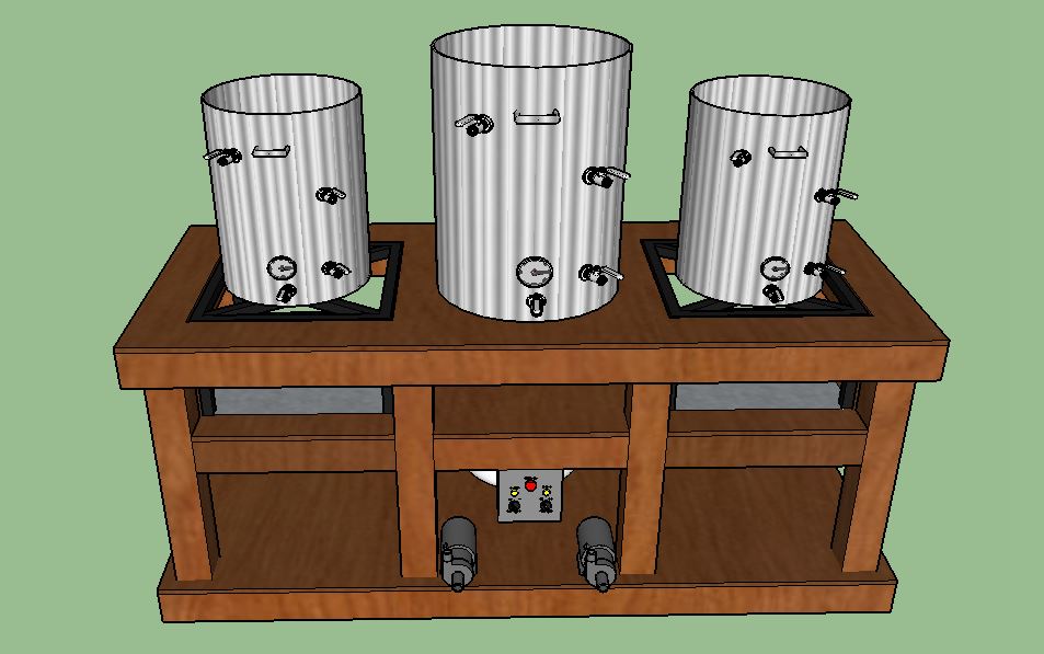
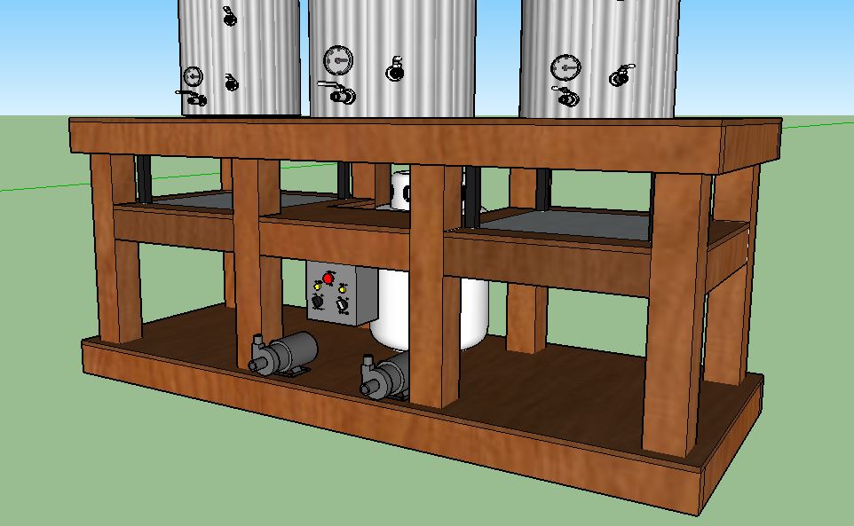
Been planning my single tier brewing system and I will have 2 march pumps (Both 110 volts). So I will be building a switch controller with an emergency stop (just in case). I am not super experienced with wiring, I understand the components and such but just haven't had the chance to actually do it.

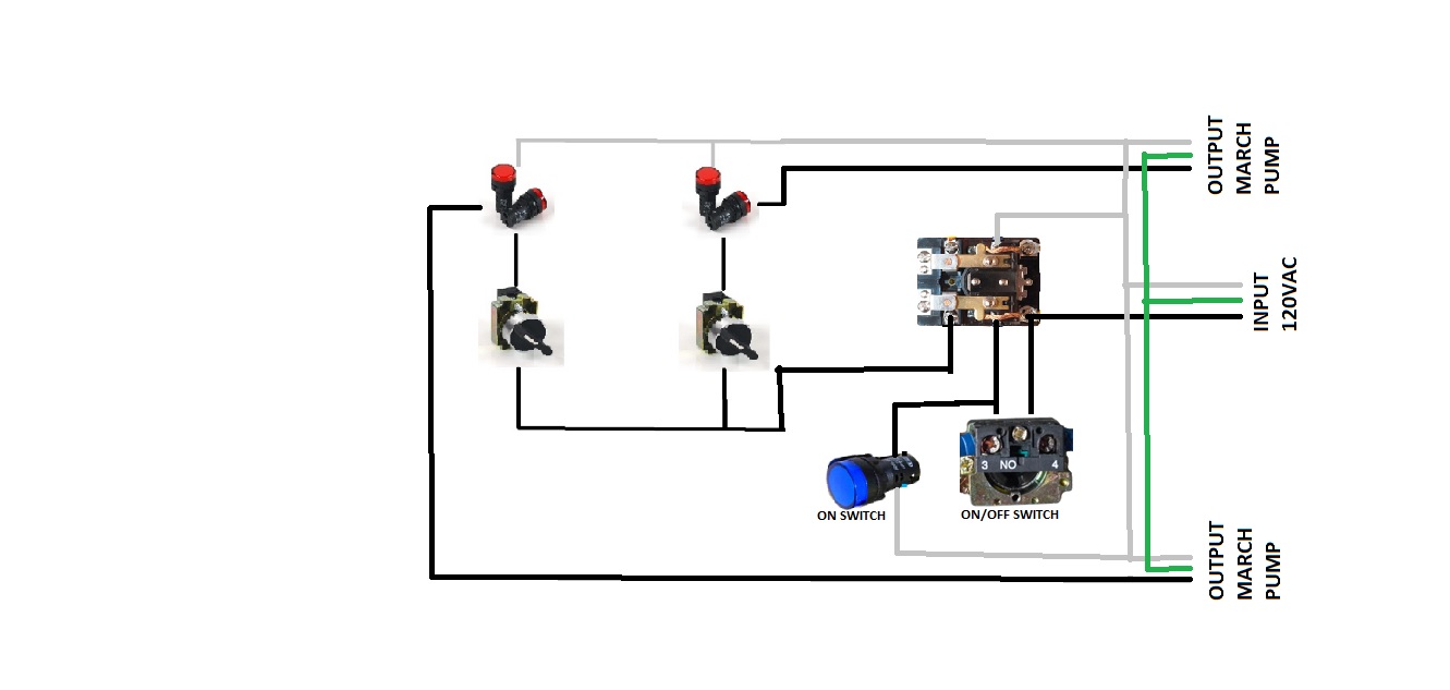
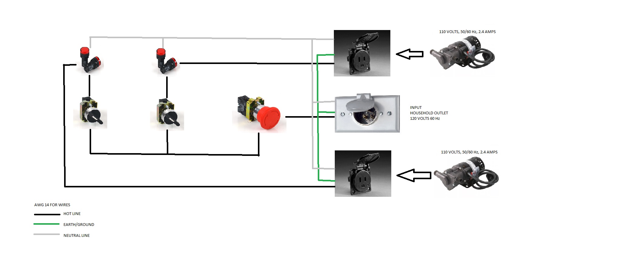
So, please look at my diagram and see if I have made some mistakes and help me correct them if so. OR any advice to improve its functionality.

A list of the elements I will use:
A junction box similar to this
2 way NO switches
Emergency Stop
LED Light 'ON' indicators
Female Receptacle
Male Receptacle
AWG #14
All needed connectors/equipment

pQWXBFS.jpg


Thank you!
 
To give an idea of what I am doing with my brewing system. This will utilize 2 - 18" propane burners with two march pumps controlled by the switching module. I will also have all SS Brewing Technology (HLT/MT/BK). And a plate chiller which is not in these designs.

oeXiCnv.jpg


SxLzWFk.jpg


Any suggestions welcome.
 
The emergency stop is rated for 10A@600V, so I am not sure it will work for 2x2.4A@110V. IIRC for 110V it should accept ~1.8A max, but don't take my word for it and make sure you check that. Same comment for the switches, make sure they accept the current.

Your mushroom is NO, that is, by default it is not closed but open. So you would have to change the black boxes below.

Furthermore, it is not permanent, so if you press it will get back to its initial state as soon as you stop pressing, which makes it unadapted to your current design.

Anyway, what you are doing is not best practice. I suggest you put a contactor after your Input plug and you use the emergency stop to interrupt current to the contactor (and by extension the whole system). There is a smart way somewhere in the forum to start the system with a button, and interrupt it with the mushroom. Don't use the mushroom to trip the GFCI if you can avoid it, also not best practice.

Your lights will be slightly on when you have nothing plugged on the receptacle. That's normal, don't get concern by it. As soon as you plug something, if it's off you will see no light.

Hope it helps.

Fantastic! I thought the Emergency Stop was a NC switch... but I need to review.

What contactor would you suggest using and how exactly does that work. I will begin researching on it but any info helps from someone who knows it better. Also, if you happen to know the forum you are speaking of please link it. I will begin looking for that as well.

Thanks for the help
 
If it stays in the position after pressing it then it shouldn't matter but if you want it to kill it when you press it then you should have a normally closed.
 
Actually according to the link for the emergency stop, you have chosen a NC switch, so it should work fine as you have drawn it. I am not sure why guindilla thinks the LED will have a slight glow when nothing is plugged in to the receptacle. Maybe somebody could explain it to me. I see no reason for the LED to be on unless the switch for that receptacle is on.

For such a simple circuit and relatively low current draw, well below the rating of the switches, I think a contractor and e-stop are overkill. The switches alone for the outlets should suffice, with the e-stop a nice feature if you think it would be safer/faster than turning off the toggle switches for both outlets in the event of an emergency.

The description of the estop switch in the link is not clear. If it is a momentary contact (actually momentary breaking of the contact) switch, then guindilla's suggestion of using a contractor makes sense, so that the current stays off after the e-switch is released. If the estop switch you have specified is set-and-reset, then the switch alone without the contractor is enough. By set-and-reset, I mean that when the estop is pressed, the switch remains open and the mushroom has to be twisted slightly to put it back to the NC position.

Okay this is more what I was thinking! I could replace it with a simple system on/off key. Just thinking in case something is happening and I freak out and need to just hit a button and turn it all off quickly. I believe the e-stop is a turn to release.

So you think I will not need a contactor? Not familiar with them and have been trying to find information and it has been tough so far - haha.
 
You are right, the e-switch is NC. I read the wrong description and it mentioned it was NO and did not lock in place. But as I was on my phone, my fingers might have played me :)

A contactor is a bit like a mechanic SSR. It could be overkill indeed (I use it for my water heaters but not the pumps).

On the residual glow, I speak from experience. Mine and others actually. It has to do with residual or leakage current if I recall correctly. When you plug something, you increase the resistance in the circuit and the leakage current stops flowing. Some people put a resistance in parallel (IIRC), but I don't find it to be a problem. Anyway, I looked at this a long long time ago, so my explanation might be wrong. The glow exists though :)

G

Great... well from what I see, what I could do (if I really need to) is put a on/off switch that is connected to the coil so that when I turn the switch it will apply electricity to the coil and pull down the pole and allow for current to flow. I could really eliminate the e-stop and just do an on/off. So really the purpose of adding the contactor would be to have no leakage current?? So it's either truly on or off.
 
Could I use this?

Relay

Does this allow for 120VAC input? I was thinking I could do this:

OxhNGcX.jpg
 
Last edited by a moderator:
Ok. Now I'm on my laptop, so I've had the time to look at this with a larger screen - incredible how this changes one's view on the problem :)

Apparently, if we believe the Electric Brewery (which I tend to do :) ) you can use directly those switches:
"The contactor only needs to support the highest current device (the pumps at approximately 1.4A), but most contactors will support up to 10A/240VAC."

Furthermore, if you look at the fourth picture of this switch (not the one you've used but from the same source) they are rated for 240V/3A.
http://www.ebrewsupply.com/3-way-2-no-contact-switch/
As a result, as 240V switches (IIRC) are better insulated than 120V, and you are drawing 2.4A (80% of 3A), you are still within safety margins. I don't think current peaks would be a problem, as per the above.

This logic should also be applicable for your main e-switch, which will have to support 4.8A. This is above the 3A they showed in one of the switches, so you should decide how you want to proceed. Two options:
1- Ignore the rating and go with the TEB indications about supporting 10A
2- Take out the e-switch as audiophool suggests
3- Use a contactor or an SSR (less secure but a pump is not as critical or dangerous as heating elements). See attachment, and just make sure the SSR you buy works with 120VAC (alternate current) in the input, they are usually 3-32VDC (direct current) to plug to PIDs.
attachment.php


attachment.php


And just for the fun of it, I've attached the e-switch I made based on advice in the forum - please do not use this as it's overkill. The key is not permanent (you turn and it comes to its initial state, it could have been a button) and the e-switch is NC. Please, do not use it here, it's overkill (likely also overkill for a control panel as well...). The advantage is that the system does require the key to be turned to be powered. So if you press your e-switch, but accidentally it gets depressed, the system does not turn on again - as it would happen with your current (no pun intended) system.
attachment.php


Good luck, and apologies for any confusion I might have created.

eswitch.jpg


SSR.jpg


Schema.jpg
 
Ok. Now I'm on my laptop, so I've had the time to look at this with a larger screen - incredible how this changes one's view on the problem :)

Apparently, if we believe the Electric Brewery (which I tend to do :) ) you can use directly those switches:
"The contactor only needs to support the highest current device (the pumps at approximately 1.4A), but most contactors will support up to 10A/240VAC."

Furthermore, if you look at the fourth picture of this switch (not the one you've used but from the same source) they are rated for 240V/3A.
http://www.ebrewsupply.com/3-way-2-no-contact-switch/
As a result, as 240V switches (IIRC) are better insulated than 120V, and you are drawing 2.4A (80% of 3A), you are still within safety margins. I don't think current peaks would be a problem, as per the above.

This logic should also be applicable for your main e-switch, which will have to support 4.8A. This is above the 3A they showed in one of the switches, so you should decide how you want to proceed. Two options:
1- Ignore the rating and go with the TEB indications about supporting 10A
2- Take out the e-switch as audiophool suggests
3- Use a contactor or an SSR (less secure but a pump is not as critical or dangerous as heating elements). See attachment, and just make sure the SSR you buy works with 120VAC (alternate current) in the input, they are usually 3-32VDC (direct current) to plug to PIDs.
attachment.php


attachment.php


And just for the fun of it, I've attached the e-switch I made based on advice in the forum - please do not use this as it's overkill. The key is not permanent (you turn and it comes to its initial state, it could have been a button) and the e-switch is NC. Please, do not use it here, it's overkill (likely also overkill for a control panel as well...). The advantage is that the system does require the key to be turned to be powered. So if you press your e-switch, but accidentally it gets depressed, the system does not turn on again - as it would happen with your current (no pun intended) system.
attachment.php


Good luck, and apologies for any confusion I might have created.

Thank you for the help, I really appreciate it. However, I have a few questions...

Why use a SSR vs a contactor?

If I use a SSR, wont I need a heatsink/fan combo or some sort of cooling system?

I am now thinking I may just use a ON/OFF switch instead of the e-stop because it will essentially be just as easy to turn it off , but do you not suggest using this idea?

What program are you using for your schematics?

Lastly, the first schematic you posted is what you are suggesting I do, correct? I looked at that SSR when reading through stuff, just don't totally understand the differences in SSR and contactors other than mechanical function.
 
Why use a SSR vs a contactor?
I found them to be cheaper, but maybe it's because I am in Europe. You can use whatever you want: contactor, SSR or even mechanical relay (this last could be even better than SSR actually).

If I use a SSR, wont I need a heatsink/fan combo or some sort of cooling system?
Not for the currents you will be working with. I do have in mine, but we are talking about more than twice the current.

I am now thinking I may just use a ON/OFF switch instead of the e-stop because it will essentially be just as easy to turn it off , but do you not suggest using this idea?
A switch sounds good, it serves the same purpose and, as mentioned before by another member, an e-switch is not totally necessary. To be honest, if you don't think you require the "emergency" side of the stop, I would eliminate it altogether and only keep the two pump switches. Again, it's not a critical side of the system.

Lastly, the first schematic you posted is what you are suggesting I do, correct? I looked at that SSR when reading through stuff, just don't totally understand the differences in SSR and contactors other than mechanical function.
Ones are mechanical, the SSR is not. If you are going to open and close many times your circuit, then an SSR is better because - not being mechanical - it will not break as easily. The contactor/relay are mechanical, and thus recommended for circuits whose state will not change often.

If you decide to put a relay, SSR or contactor, I think my schema is the way to go. If you decide not to put any general switch, I think you know how to do it :) Just take out the e-switch from your first schema.

If you want to save some space, consider adding illuminated switches such as those and you will save yourself the use of LED indicators:
http://www.ebrewsupply.com/red-led-toggle-led-2-way-switch/

Cheers.
 
I found them to be cheaper, but maybe it's because I am in Europe. You can use whatever you want: contactor, SSR or even mechanical relay (this last could be even better than SSR actually).


Not for the currents you will be working with. I do have in mine, but we are talking about more than twice the current.


A switch sounds good, it serves the same purpose and, as mentioned before by another member, an e-switch is not totally necessary. To be honest, if you don't think you require the "emergency" side of the stop, I would eliminate it altogether and only keep the two pump switches. Again, it's not a critical side of the system.


Ones are mechanical, the SSR is not. If you are going to open and close many times your circuit, then an SSR is better because - not being mechanical - it will not break as easily. The contactor/relay are mechanical, and thus recommended for circuits whose state will not change often.

If you decide to put a relay, SSR or contactor, I think my schema is the way to go. If you decide not to put any general switch, I think you know how to do it :) Just take out the e-switch from your first schema.

If you want to save some space, consider adding illuminated switches such as those and you will save yourself the use of LED indicators:
http://www.ebrewsupply.com/red-led-toggle-led-2-way-switch/

Cheers.

Thank you for the quick response, I really appreciate the help. I'm actually studying Electrical Engineering but we don't cover a lot of things like these which is interesting, mostly focus on power electronics. I just searched the schematics of an SSR and now I get how it works - haha. Kept looking into the contactors rather than SSR.

I will update as I go along. I should have the system built by January. I want to leave some space because I would eventually like to add PID's and solenoids/pilots to control the propane burners. Wont be necessary so a little while
 
This got out of hand in a hurry. Your original design is fine as drawn. You do not need any relays or contactors. Switch max current ratings don't go down when used at or below their max voltage rating (although max current/voltage ratings may be different for AC vs. DC, but not a concern for your design.)

Your original E-stop switch is NC and latches when pressed. Note the arrows on the face of the mushroom button indicating which way to turn the button to unlatch.

The lights will not glow when the switches are off. That phenomenon occurs with SSR switched 240V systems when the element is not plugged in. The leakage current that dimly lights the LED's is thru the SSR. Mechanical switches don't have leakage current (unless they are defective.)

All you need to do is make sure you power the switch box from a GFCI protected outlet.

Brew on :mug:

Well great, i appreciate it. I still may switch out the NC e-stop with a on/off switch.

Thank you for the help. You guys are great help. Even if it was correct in the beginning I now understand SSR's and contactors :fro:
 
Back
Top