Controller build, SSVR and schematic question

Homebrew Talk - Beer, Wine, Mead, & Cider Brewing Discussion Forum

Help Support Homebrew Talk - Beer, Wine, Mead, & Cider Brewing Discussion Forum:

This site may earn a commission from merchant affiliate links, including eBay, Amazon, and others.

weawer

Member
Joined
Aug 14, 2014
Messages
14
Reaction score
0
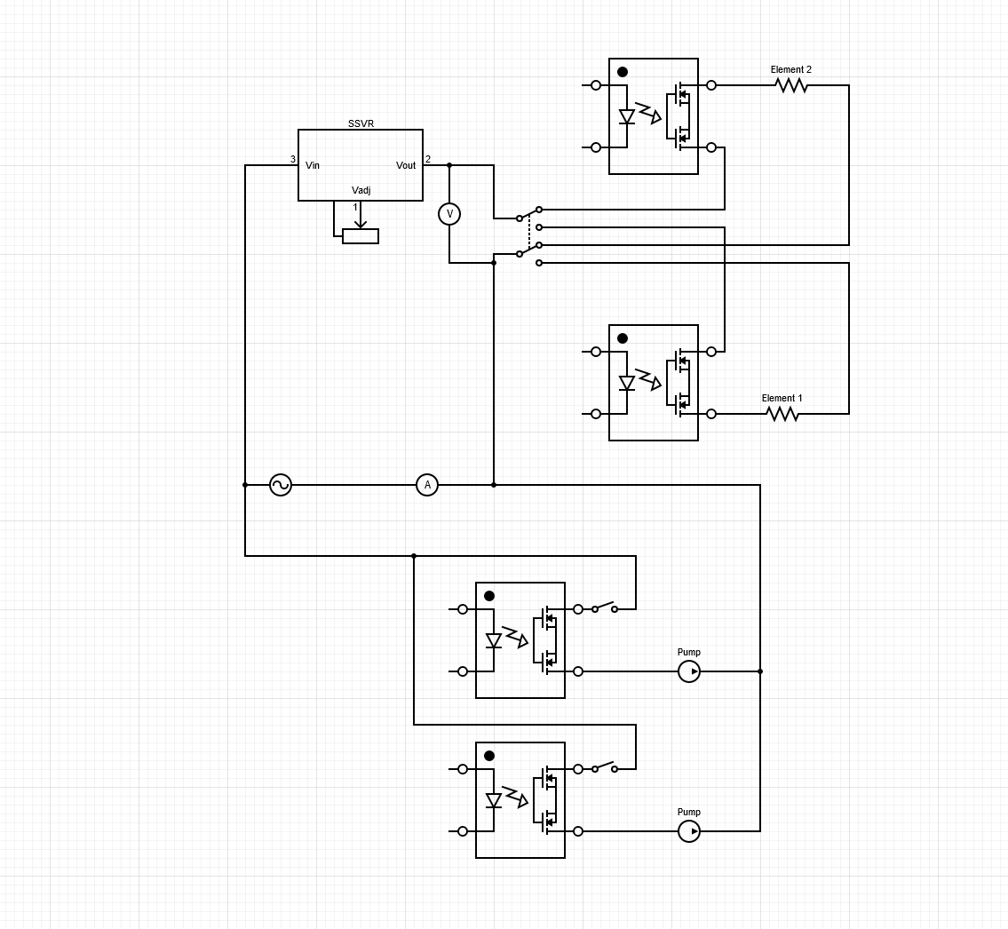
Hey I am building a new controller and i would be very grateful if someone could have a look over a diagram in specifically the ssvr part of it since i have not worked with such devices before and i am having a hard time finding wiring diagrams for this specific usecase. The thought is to be able to regulate the volt down a bit during boil and mash with rims tube and i had a ssvr lying about so i thought why not use it. Im in the eu so im running 230v.

The switch between the elements is a 2 pole with a 0 position just as a sidenote. The diagram software didnt have any icons like that for some reason.
There is also a few scattered fast/slow blowing fuses and everything is of course grounded.

Have i done something terminally stupid here that i have not spotted? Will the ssvr work as i believe or might it disturb the rest of the circuit?
 

Attachments

  • Namnlös.png
    Namnlös.png
    43.6 KB · Views: 1
Sorry no one else has weighed in here yet. I have brain damage and memory loss so I try to exercise extreme caution in answering wiring questions.. That said, at least this'll be a bump back to the top of the forum.
Your SSVR wiring looks OK, but I am wondering about the numbers in the diagram: Pins 1 & 2 are for the power, 3 & 4 are for the pot. Is your 2-pole element selector rated for the current?(..those things are pricey)
I'm wondering why you're using contactors on the pumps...wouldn't switches be more appropriate?
Here's the page for Aubers SSVR, with a diagram and link to its manual:
https://www.auberins.com/index.php?main_page=product_info&cPath=53&products_id=353Hope this is of some use.
 
Agree that SSRs are a little overkill on pumps, but maybe there's some logic that we're not seeing. The element selector question above is valid as 30 amps is pretty big load for a switch. Usually this would be done with a pair of 2 pole contactors and a low current selector switch to activate the coils of either.
 
Sorry no one else has weighed in here yet. I have brain damage and memory loss so I try to exercise extreme caution in answering wiring questions.. That said, at least this'll be a bump back to the top of the forum.
Your SSVR wiring looks OK, but I am wondering about the numbers in the diagram: Pins 1 & 2 are for the power, 3 & 4 are for the pot. Is your 2-pole element selector rated for the current?(..those things are pricey)
I'm wondering why you're using contactors on the pumps...wouldn't switches be more appropriate?
Here's the page for Aubers SSVR, with a diagram and link to its manual:
https://www.auberins.com/index.php?main_page=product_info&cPath=53&products_id=353Hope this is of some use.

Agree that SSRs are a little overkill on pumps, but maybe there's some logic that we're not seeing. The element selector question above is valid as 30 amps is pretty big load for a switch. Usually this would be done with a pair of 2 pole contactors and a low current selector switch to activate the coils of either.

Hey thanks to you both for answering. I did have a look at the auberins one earlier and it gave my some ideas of what i was dealing with and to only use em on resistive loads. So it was absolutely of use.

Im not entirely sure where you see an contactor but the symbols are supposed to be an ssr and a switch (on each of the pumps), its prob overkill but i was thinking of how far i wanted to push automation when i started the build. The plan has now changed a bit and I'll probably disconnect the ssr down the line. Now they just act as a doublecheck so i dont start the wrong pump.

Im not sure if the pins are correct this was just how the drawing software had it configured. Ill give it a look once it arrives.

The 2 pole switch is a changeover cam switch and its rated for 20A 240V. The larger of the 2 elements draws 13 amps so i do have quite a bit of headroom in regards to the ratings on it. It was still quite expensive though as i didnt really want to gamble on the various cheap china ones.
 
Last edited:
The part I forgot to include above: While I too, prefer a knob-based power-controller for intuitive adjustment of the BK, ..maybe it's just me, but I wouldn't use it to control a RIMS tube...too much risk of a scorching overshoot trying to constantly ride it through the mash. Even if you're on a tight budget, if you shelled out for one of the Auber DSPR 320 units and a standard SSR, you'd only have to build it once.
 
The part I forgot to include above: While I too, prefer a knob-based power-controller for intuitive adjustment of the BK, ..maybe it's just me, but I wouldn't use it to control a RIMS tube...too much risk of a scorching overshoot trying to constantly ride it through the mash. Even if you're on a tight budget, if you shelled out for one of the Auber DSPR 320 units and a standard SSR, you'd only have to build it once.
yep thats some good advice and it is how i am intending to run it mostly. My rimstube has a 2.5kw element in it though so its a bit overpowered at the moment hence the idea to restrict it down a bit so its less likely to scorch and overshoot the set temp while its being run by a PID through the ssr thats connected after the ssvr.
The plan is to use a raspberry pi with Craftbeerpi 4 as the controller unit and have that running as pid for both elements.
 
My rimstube has a 2.5kw element in it though so its a bit overpowered at the moment hence the idea to restrict it down a bit so its less likely to scorch and overshoot the set temp while its being run by a PID through the ssr thats connected after the ssvr.
Sorry, but I'm completely lost by this. It sounds like you're scapping the above schematic.... PID's do voltage-control for SSRs, SSVRs are resistance-contolled that aside, you don't connect the two, so an element-selector wouldn't be applicable...am I missing something? Can you do an updated schematic?
 
Sorry, but I'm completely lost by this. It sounds like you're scapping the above schematic.... PID's do voltage-control for SSRs, SSVRs are resistance-contolled that aside, you don't connect the two, so an element-selector wouldn't be applicable...am I missing something? Can you do an updated schematic?
the schematic is the same ive just left the low voltage side out of it since i didnt feel it was necessery to include since its just a pi with its GPIO pins connected to the SSRs

However im not sure we are on the same page here. The setup in the above schematic for the element side is as follows. SSVR (controlled by a pot) -> Selector switch -> 2 SSRs (controlled by a pid/raspberry) -> Element.

Solid State Relays dont do voltage control they just turn on and off and will be the main way of controlling temperature. The Solid State Voltage Regulator is there to limit the voltage running to the elements when desired for example to the rims tube to prevent scorching and during boil since a pid is not that useful there.
 
Last edited:
Sorry, my bad..the afforementioned brain damage includes visual focus and processing difficulties, when I saw the box labelled "SSVR" I just assumed (without zooming in) that the other 4 units were contactors...and I Should have said 'pulse' and not 'voltage'..thing with that is if you connect a PID-contolled SSR to a variable current as provided by an SSVR you may end up with unpredictable results; over and undershoots. If your PID is reliable, the SSVR is redundant and more likely to degrade performance.
As @Bobby_M said; SSR's on the pumps are overkill...if the idea is to automate flow-rate, solonoid-valves on the outputs are a more reliable option (which, yeah; want SSRs, but separate from the power supply)
 
Solid State Relays dont do voltage control they just turn on and off and will be the main way of controlling temperature. The Solid State Voltage Regulator is there to limit the voltage running to the elements when desired for example to the rims tube to prevent scorching and during boil since a pid is not that useful there.
SSVRs don't control voltage either, they just switch faster than SSRs. SSRs generally let an integral number of power cycles thru each time they are triggered, and have some circuitry that turns them on as the voltage crosses 0 (so no electrical noise is generated.) SSVRs are normally turned on at some point during every power cycle - early in the cycle for higher powers and later in the cycle for lower powers. Both SSRs and SSVRs automatically shut off at the end of the current power cycle, if the trigger signal is removed. So, both have pulsed outputs, but if you apply low pass filtering, both look like they reduce the voltage to the load.

Putting an SSVR in series with an SSR will just double the power lost to switching, and double the amount of heat that your system needs to dissipate.

Brew on :mug:
 
Sorry, my bad..the afforementioned brain damage includes visual focus and processing difficulties, when I saw the box labelled "SSVR" I just assumed (without zooming in) that the other 4 units were contactors...and I Should have said 'pulse' and not 'voltage'..thing with that is if you connect a PID-contolled SSR to a variable current as provided by an SSVR you may end up with unpredictable results; over and undershoots. If your PID is reliable, the SSVR is redundant and more likely to degrade performance.
As @Bobby_M said; SSR's on the pumps are overkill...if the idea is to automate flow-rate, solonoid-valves on the outputs are a more reliable option (which, yeah; want SSRs, but separate from the power supply)
That explains the confusion then. Yeah ill remove the SSRs from the pumps and just run em off the switches instead. ill have a think about how i want to proceed. Thanks for your input.

SSVRs don't control voltage either, they just switch faster than SSRs. SSRs generally let an integral number of power cycles thru each time they are triggered, and have some circuitry that turns them on as the voltage crosses 0 (so no electrical noise is generated.) SSVRs are normally turned on at some point during every power cycle - early in the cycle for higher powers and later in the cycle for lower powers. Both SSRs and SSVRs automatically shut off at the end of the current power cycle, if the trigger signal is removed. So, both have pulsed outputs, but if you apply low pass filtering, both look like they reduce the voltage to the load.

Putting an SSVR in series with an SSR will just double the power lost to switching, and double the amount of heat that your system needs to dissipate.

Brew on :mug:

I thought SSVRs worked by phase angle control (just removing parts of the since wave), is that what you mean by "they just switch faster"?
 
Last edited:
I thought SSVRs worked by phase angle control (just removing parts of the since wave), is that what you mean by "they just switch faster"?
Yes. The output waveform is kind of a rounded sawtooth.

Brew on :mug:
 
Back
Top