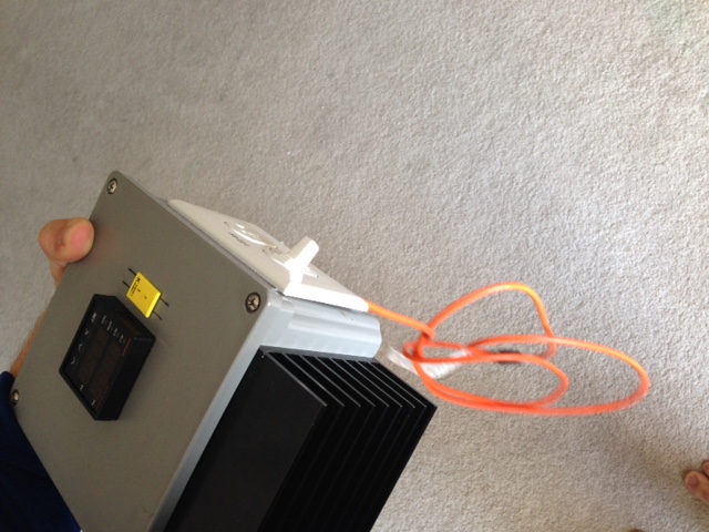
Step by Step build a 110v portable PID controller

Homebrew Talk - Beer, Wine, Mead, & Cider Brewing Discussion Forum

Help Support Homebrew Talk - Beer, Wine, Mead, & Cider Brewing Discussion Forum:

This site may earn a commission from merchant affiliate links, including eBay, Amazon, and others.
Excuse my ignorance, but can you run the independent element AND the PID side of of the same wall outlet? It looks like that's what you're doing but I just wanted to make sure you didn't have a higher amp circuit installed.

Also, I would like the option of doing 10 Gallon batches. Would the two 2000W 120V elements be able to boil the required water/wort for a 10 gallon batch?

Thanks for the write up, this is great stuff!
 
How hot does the heat sink get? Any risk of melting the box?

It gets pretty warm, but I don't think that it'll get hot enough to melt the box. Remember that I only use the PID for mashing. I unplug it and plug my element(s) straight into the wall to boil, so that helps with heat sink temps I'm sure.

Excuse my ignorance, but can you run the independent element AND the PID side of of the same wall outlet? It looks like that's what you're doing but I just wanted to make sure you didn't have a higher amp circuit installed.

Also, I would like the option of doing 10 Gallon batches. Would the two 2000W 120V elements be able to boil the required water/wort for a 10 gallon batch?

Thanks for the write up, this is great stuff!

Probably not. The elements I use draw too much current to both be on a 20A breaker. That is a double gang GFCI receptacle fed by 2 different 20a circuits that I run my kettle on.

Here is a good thread to read about 2,000w, 120v, 10 gallon batches.
https://www.homebrewtalk.com/f170/110v-10-gallon-batches-possible-416468/
 
I'd like to know the answer to this one also.

I want to use two 2000W elements.

:)

I am looking to build this same setup but with two (or three) elements hooked up to the same PID. I would like to do this so that I can leave all three elements plugged in and walk away without having to worry about overshooting my mash temp or boilovers (I plan on setting the target temp on the PID to just under boiling and then turning it on to manual mode once I am ready to watch it closely for the final few degrees.

Is this possible to do? I don't have any electrical experience so any input would be appreciated. I drew up a diagram of what I thought might work using an extra switch and SSR but this could be completely incorrect.

If anyone could let me know if I can change anything to make this work (short of buying another PID and thermocouple) it would be greatly appreciated!

Thanks!
 
I built mine to control 2 elements on one pid.. You just need to have a ssr for each element and jumper the signal output from PID to both ssr's
 
I built mine to control 2 elements on one pid.. You just need to have a ssr for each element and jumper the signal output from PID to both ssr's

I know this thread is old, but I'm looking to do the exact build you have in your profile. Any chance you have more photos or a parts list?
 
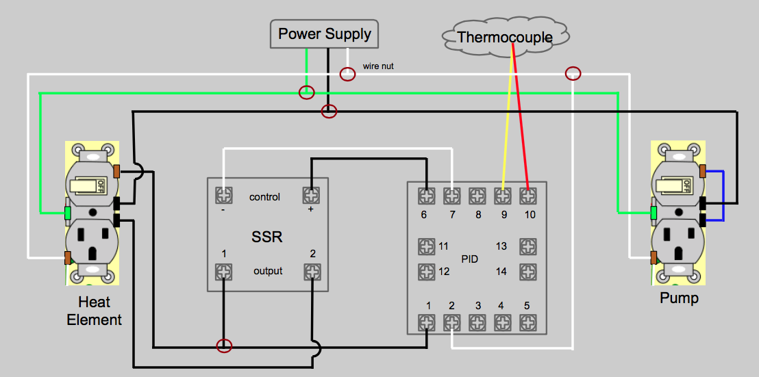
great post! I am trying to build the countertop version of brutus 20. The difference with this controller and what I am trying to build is that I would like to have an extra switch/plug combo that does not need to be controlled by the PID in any way, just so I can switch the pump on and off and keep everything neat in one box. I know it can be done, the plans for the CTB20 we just lacking in this area, and I am not an electrician. If anyone could let me know if this wiring diagram I whipped up looks correct, I would be very grateful. I put the switch/plug combos on the diagram how the screws are on the model I purchased.

Screen Shot 2014-11-28 at 5.48.29 PM.png
 
If you want 15Amp load use a 14AWG wires , for 20 Amp use 12AWG. Any wires coming to/from PID can be any size up to 22AWG
 
I'm going to be building a single element PID control box for a rims tube. Ill be using a 5500 watt/ 240 volt element wired up at 120v. At 120v thats around 11.46 amps.

Now, I seem to remember reading somewhere that you should figure on only using 80% of amperage capacity as a safety measure (any comments on this statement?). So 11.5amps/80% = 14.3 amps.

Would you recommend I wire up my box for 15 amps or 20 amps? The breaker is a 20 amp breaker. I haven't decided if I am going to wire my pump or anything else up in this box.
 
Excellent documentation, and as others have commented, clever positioning of the SSR heat sink in your enclosure. Question, how are your heater elements wired and secured in the kettle? Looks like there are two? Is one plugged directly into a wall outlet? Thanks.
 
great post! I am trying to build the countertop version of brutus 20. The difference with this controller and what I am trying to build is that I would like to have an extra switch/plug combo that does not need to be controlled by the PID in any way, just so I can switch the pump on and off and keep everything neat in one box. I know it can be done, the plans for the CTB20 we just lacking in this area, and I am not an electrician. If anyone could let me know if this wiring diagram I whipped up looks correct, I would be very grateful. I put the switch/plug combos on the diagram how the screws are on the model I purchased.
238714d1417216142-step-step-build-110v-portable-pid-controller-screen-shot-2014-11-28-5.48.29-pm.png


I would be curious to know if this is correct as well.
 
No. The ground is routed to the neutral screws on the the receptacles and vise versa.

That wiring diagram is correct. I plug my box into a wall, GCFI, plug my pump into the box and my heat element into the other side.

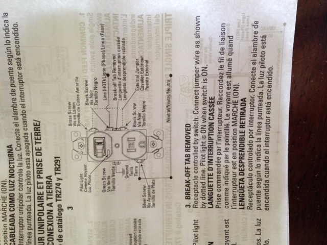
The screws are in a different position from some manufacturers of switch plug combos, but I colored them in the correct position from the receptacles that I found at my hardware store and followed the directions in their box on how to create a switch controlled outlet (pump) and a master switch/PID controlled outlet.

Just brewed my first batch with it last weekend and it worked perfectly, no smoking hole in my kitchen.

Interesting. What's the make/model of the receptacle?
 
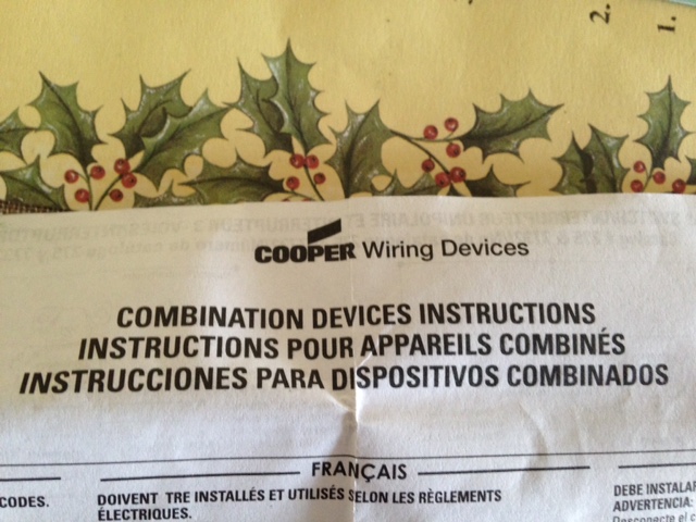
Here are the shots from the manual that came with my receptacle. I based my wiring diagram off of this. my controller box works very well. The HE receptacle switch power up the PID and the SSR controls power out of the receptacle to HE. The pump is a secondary receptacle and the switch controls the pump directly and nothing else.
 
Interesting. What's the make/model of the receptacle?

Here are the shots from the manual that came with my receptacle. I based my wiring diagram off of this. my controller box works very well. The HE receptacle switch power up the PID and the SSR controls power out of the receptacle to HE. The pump is a secondary receptacle and the switch controls the pump directly and nothing else.

If you know how to read the colors or a manual that came with whatever receptacle purchased, it shouldn't matter where they are located though.

image5.JPG


image3.JPG


image2.JPG


image1.JPG


image6.JPG


image7.JPG
 
Excellent documentation, and as others have commented, clever positioning of the SSR heat sink in your enclosure. Question, how are your heater elements wired and secured in the kettle? Looks like there are two? Is one plugged directly into a wall outlet? Thanks.

Hey, been gone for a while.

Yes, one is plugged directly into the wall. I will use it to rapidly get the water close to dough-in temp, then unplug it and let the PID controlled element take me where I need to go. The single element is plenty to maintain temp throughout the entire mash process.

When I am ready to boil, I unplug the PID controller, put it in the cabinet and plug both elements directly into the wall.
 
Are you able to place this PID in manual mode and just control the output % when you are boiling?
 
I am looking at doing a setup similar to this one but only using 1 5500w 240v element. I intend to boil in this kettle and use my coolers to mash with then sparge into this kettle. What would I need to change to use the 5500w element. I plan on using the outlet for my stove to plug into. I know this post is old just hoping for so insight if this would work for what I want to do.
 
So, ignorance showing here:

Does this wiring diagram have the pid able to monitor the temps before you flip the switch (literally) and turn on the heating element?

that way i could verify the temp of the wort / things are working before turning on the element (to prevent scorching).

thanks!
 
Are you sure? You might want to look again... From what I see the switch will in fact kill the power to the element outlet.

I'll take your word for it. It just looks to me like it will kill power to the PID as well.
 
238714d1417216142-step-step-build-110v-portable-pid-controller-screen-shot-2014-11-28-5.48.29-pm.png


I would be curious to know if this is correct as well.


Bump. I realize this is an old post but I am interested in building the controller featured on the thread with an added pump switch that the quoted post asks about. Appreciate any helpful information!
 
I think not, at first glance it looks to me like earth ground (green) and neutral (white) are switched. We'll need to know the specific model of your switch/receptacles to give you a better answer.

(edit)
This looked familiar, as I tried to answer this question once before. The poster that originally posted that diagram says this is correct in THEIR case, it just looks funny to me. But it still depends on the specific model receptacles that YOU buy.

I plan to get this model switch/receptacle https://www.amazon.com/dp/B00004YUMX/?tag=skimlinks_replacement-20
 
Last edited by a moderator:

That's 12.5A, that + a pump might be cutting it close for a 15A circuit. I can't find a diagram on that Leviton so I can't be much help in regard to wiring. Once you get it in hand there will be a diagram on the box.
 
Back
Top