New BruControl Build

Homebrew Talk - Beer, Wine, Mead, & Cider Brewing Discussion Forum

Help Support Homebrew Talk - Beer, Wine, Mead, & Cider Brewing Discussion Forum:

This site may earn a commission from merchant affiliate links, including eBay, Amazon, and others.
It is for a 3-way valve where one position is to hand off the freshly boiled and cooled wort to the fermentation system, which does not yet exist. At the time, I had a hose looped into a bucket. Unfortunately, it wasn't a 20-gallon bucket.

lloyd.jpg
 
I got another very helpful tip from @BrunDog today, which prompted another trip to the google box to part with more of the fruit of my labors.

He made the observation that if my three temp sensors are reading the insides of the kettles, the lag time between PID-exerted control over the HLT element and the response of the sensor in my MLT may cause some big temperature oscillations in the MLT that will never really smooth out.

His recommendation was to add a fourth PT-100 to the output of the HERMS coil, and to key the PID control to that sensor. It made sense, so I ordered a PT-100 that can screw into a tee fitting which I will mount where the output of the HERMS coil enters the MLT. I also had to order another tee and an RTD amplifier board. Fortunately, I've got the spare wires in place to handle the extra sensor, so it's a lot smaller chore than it would be if I had to run more cables.
 
I totally agree with that approach - controlling the HLT based on the HEX output.
Then you adjust the HLT "set point" based on the actual mash temperature, which will account for thermal losses.
On my 3V2P herms I usually run the HLT 1.5-2°F above the target mash temperature while circulating between 2 and 3 gpm (flow rate is important as I'm running a 20g uninsulated SS MLT)...
Cheers!
 
Update: My workbench had become a disaster area, with little bits of wire, tiny ziploc bags, Phoenix jumpers, Deutsch pins, camlock fittings, and all manner of tools and odds and ends scattered everywhere. So rather that do the sim brew I was planning on, I tackled the monster.

Once I got everything picked up and organized, it occurred to me that I still hadn't started the fermentation controller. It would be kind of stupid (see my Monday morning post above) for me to brew up a half-barrel of beer and have no place to put it other than a handy bedroom closet. One thing led to another and the water brew fell by the wayside.

I was going to run the brew today, but I think I'll start wiring this up instead. I am waiting on a couple of parts to add another PT-100 to the brewstand. The sim brew will keep until I get that and the op amp board that @BrunDog is working on installed.

One thing I did figure out is that ¼" PVC board is really adaptable for mounting circuit boards. I used thin strips to mount the relay board, and I used a small square to mount the Mega. It's not going to take a lot of abuse, but I think it will do this job just fine.

IMG_1452.JPG
IMG_1453.JPG
IMG_1454.JPG
 
I ran a simulated brew today. Everything went well enough that I think I'm ready to run a live brew! Naturally, there are a couple of things to tweak, but there wasn't anything that I would call a show-stopper. I took some notes, and I think I will develop a checklist to work off of for the first few brews. Things are looking up!
 
I now have a place to put the beer I'm going to brew this weekend. I ran the HEX hoses from the chiller to and from the ferm chamber last night, and fired it up for some testing this morning. After three hours with no thermal mass in the chamber, I have what looks to be correct behavior for the chiller compressor and for the pond pump submerged in the glycol bath. Man, but this is gonna be such an improvement over "Ferment for two weeks at random closet temperature."

Screen Shot 2018-05-17 at 12.23.36 PM.png
 
I ran a batch through my new system for the first time yesterday. I did an oatmeal stout recipe that I've had pretty good luck with in the past. Mechanically, the new rig performed very well. My process needs some tweaking here and there. Once I get a little more comfortable, I'll be able to find efficiencies that will save time.

The only real issue that came up was unrelated to the system. At the very end of the brew, the last step was to put the carboys into the ferm chamber. As I was lowering the second of three, the bottom of the carboy broke clean off. It was already close to midnight. What a frickin' mess! I got the worst of it cleaned up, then had to deal with the spent grains and kettles.

Needless to say, the final cleanup has been deferred until this morning.

Overall, I'm really happy with the way the rig works. 10 gallons of stout with an OG of 1.064 are bubbling away in a chamber at exactly 67ºF.

IMG_1497.JPG


https://www.facebook.com/photo.php?fbid=1272879356175678&set=gm.983560848478060&type=3&ifg=1
 
Update: I've been dealing with a weird temp sensor issue in my system. Thanks to the data logging and graphing capabilities of BruControl, and the patient but relentless tech support from @BrunDog over in the BruControl thread, it looks like it's close to being solved.

In a nutshell, a small ice cube relay can allow an inductive load like a pump or a fan to put a measurable EMI spike onto the 5v power circuit when the relay is shut off and the contacts open. Installing a metal-oxide varistor (MOV) in parallel with the power feed to the pump or fan seems to clamp the EMI spike.

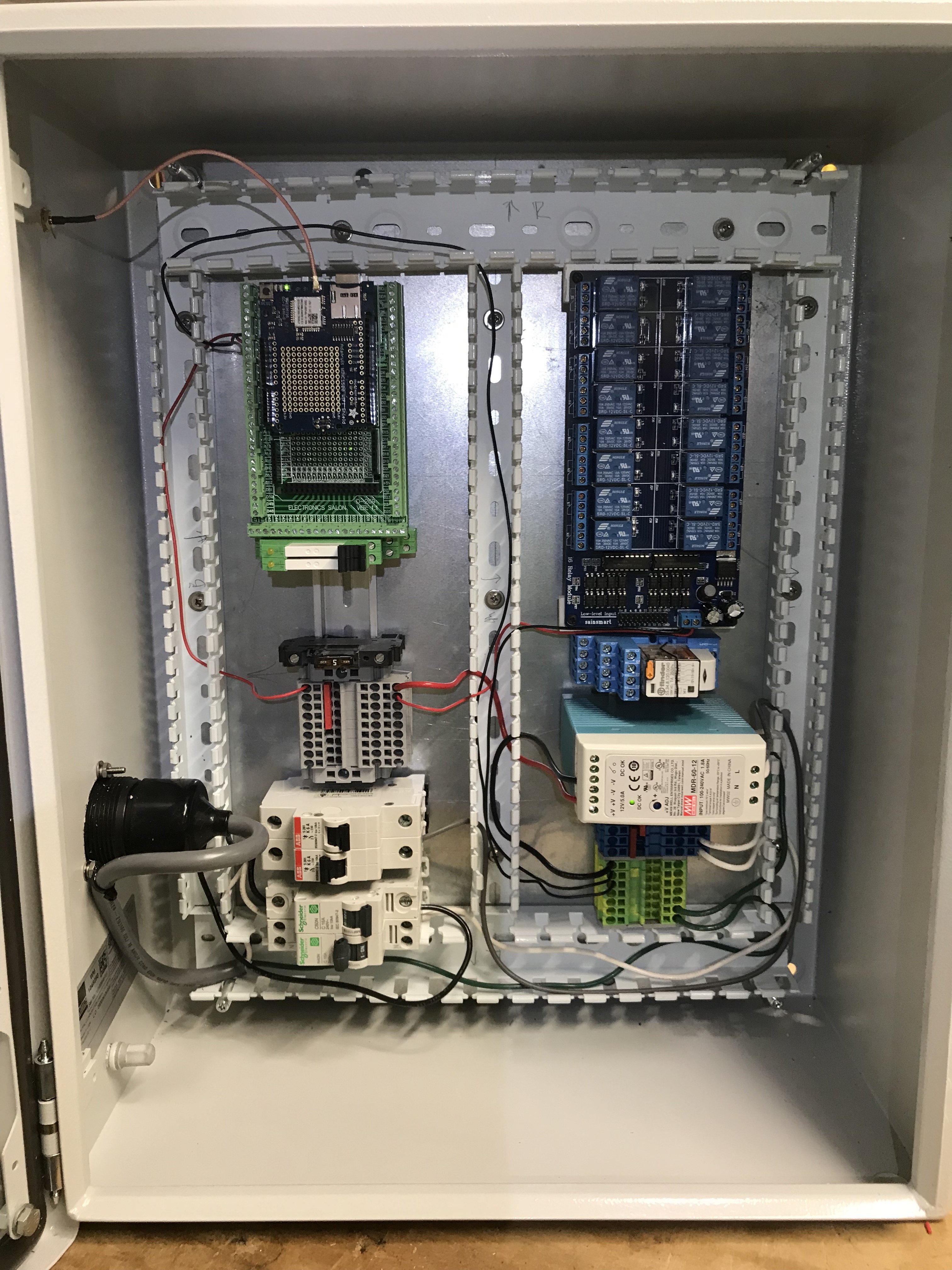
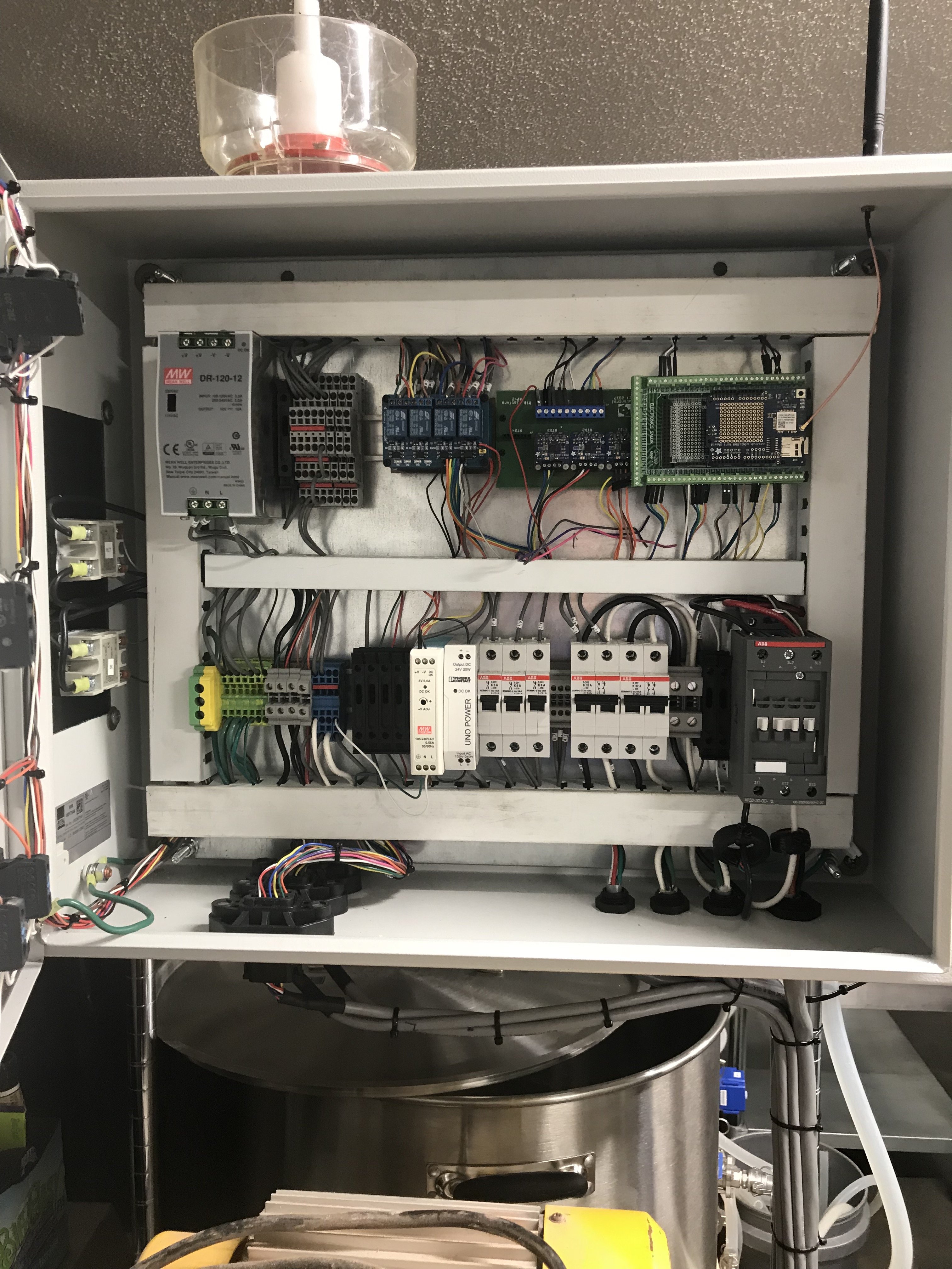
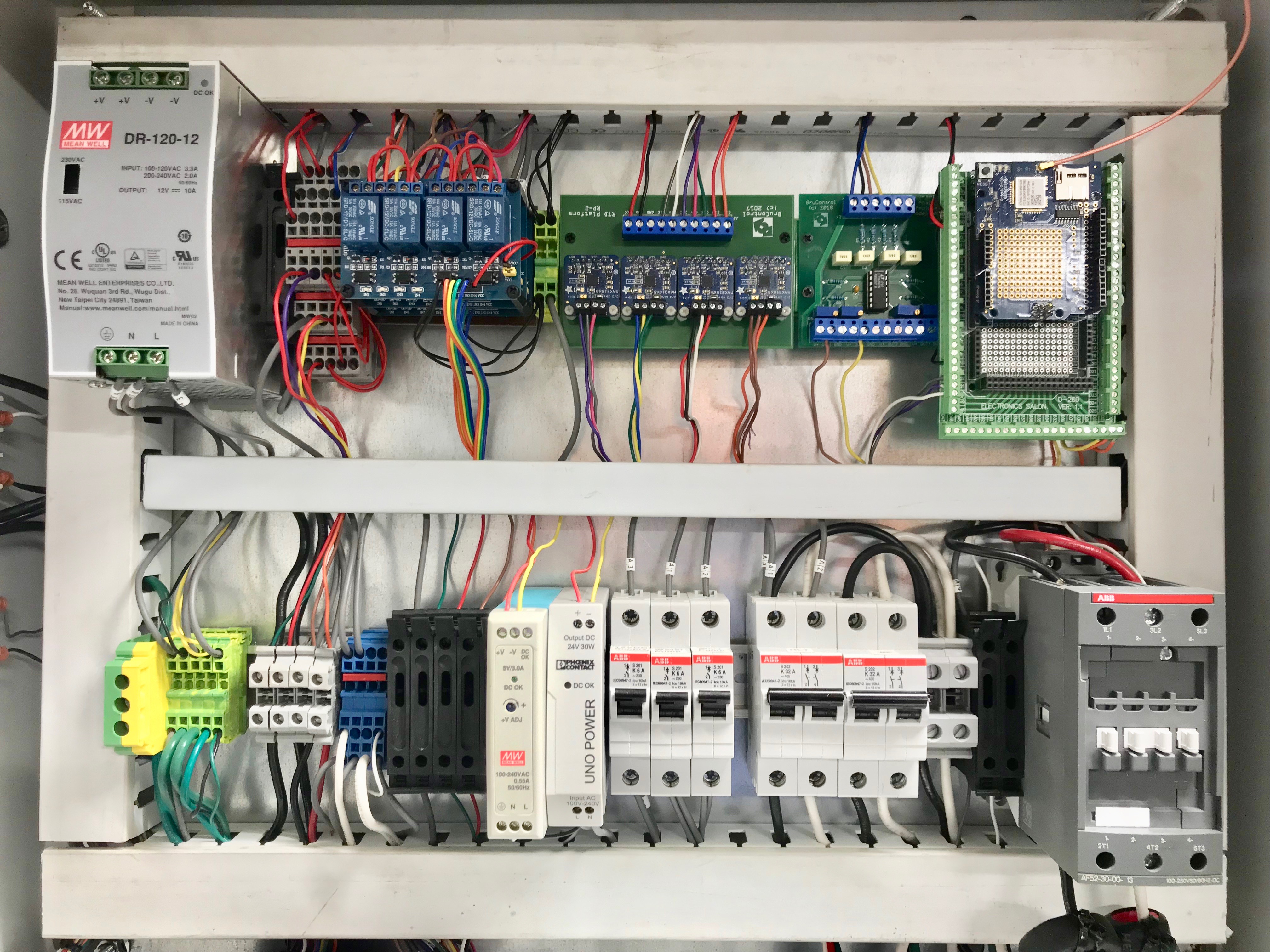
Installing the MOVs in my brewstand controller prompted me to take advantage of an opportunity to clean up a bunch of kludgy wiring that sprouted up while troubleshooting this EMI problem. I wound up taking the entire top rail apart and redoing everything.

Originally, I connected the relay boards to the Mega with Dupont jumpers. The runs were too long for one jumper, so I connected them back to back. I never did like it, because I was always fussing over inadvertently disconnecting one, and I also didn't like the little bit of exposed metal on the female connectors. All gone now. A lead from the relay board header pin now goes into the tray and is connected to a piece of 18AWG via a heat shrink butt connector. I managed to scrounge up enough 18AWG that I could keep the color coding consistent.

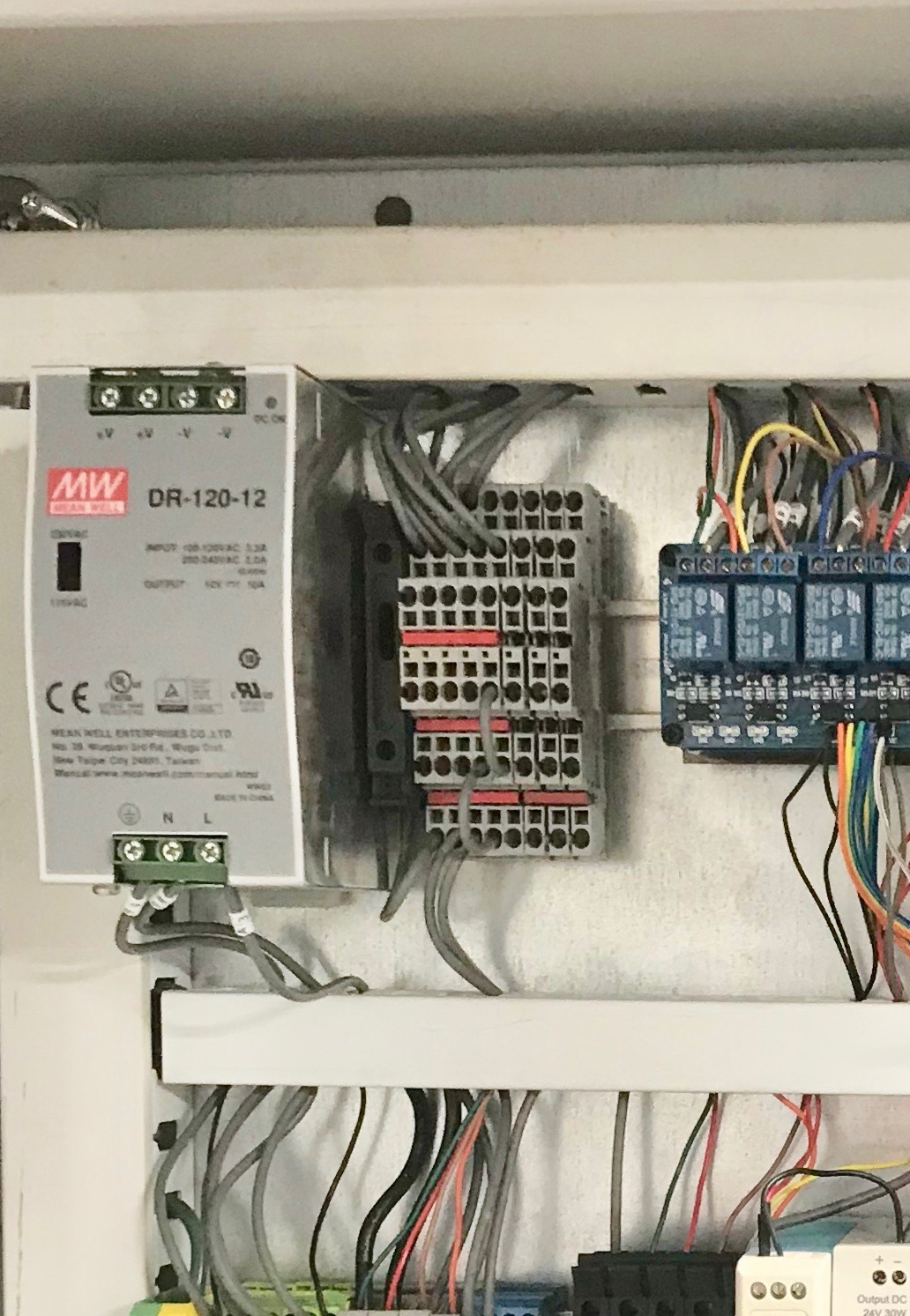
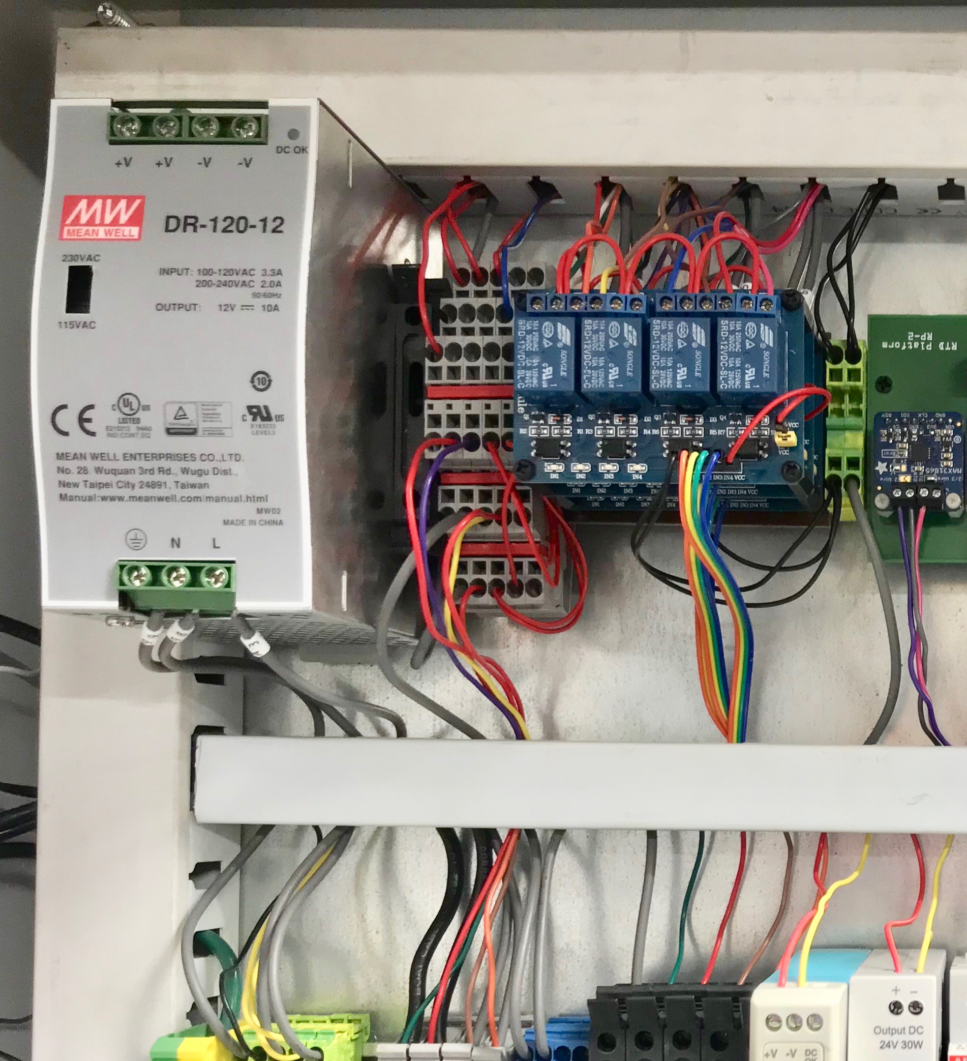
I also redid my power supply wiring. There had been a number of changes from the original design, including the addition of 5v and 24v power supplies. I wound up with 2-3 leads tied down to the DC+ terminal on both the new supplies. Originally, I used triple-stack Phoenix blocks as a 12v distribution bus. With the rewire, I now have all three DC voltages available on the same Phoenix blocks. 12v is on the lower tier, then 24v in the middle and 5v on top. See the detail pics for the particulars. I also eliminated individual 12v feeds to the relay "Common" terminals, and just daisy-chained them.

Finally, in order to recover rail space for the op-amp board, I rotated the Mega assembly. Before and after pics of the top rail are attached. The whole box looks cleaner now.


IMG_1470 (1).jpg
IMG_1470.jpg
IMG_1611 (1).jpg
IMG_1611 (2).jpg
IMG_1611.jpg
 
Update: I've been dealing with a weird temp sensor issue in my system. Thanks to the data logging and graphing capabilities of BruControl, and the patient but relentless tech support from @BrunDog over in the BruControl thread, it looks like it's close to being solved.

In a nutshell, a small ice cube relay can allow an inductive load like a pump or a fan to put a measurable EMI spike onto the 5v power circuit when the relay is shut off and the contacts open. Installing a metal-oxide varistor (MOV) in parallel with the power feed to the pump or fan seems to clamp the EMI spike.

Installing the MOVs in my brewstand controller prompted me to take advantage of an opportunity to clean up a bunch of kludgy wiring that sprouted up while troubleshooting this EMI problem. I wound up taking the entire top rail apart and redoing everything.

Originally, I connected the relay boards to the Mega with Dupont jumpers. The runs were too long for one jumper, so I connected them back to back. I never did like it, because I was always fussing over inadvertently disconnecting one, and I also didn't like the little bit of exposed metal on the female connectors. All gone now. A lead from the relay board header pin now goes into the tray and is connected to a piece of 18AWG via a heat shrink butt connector. I managed to scrounge up enough 18AWG that I could keep the color coding consistent.

I also redid my power supply wiring. There had been a number of changes from the original design, including the addition of 5v and 24v power supplies. I wound up with 2-3 leads tied down to the DC+ terminal on both the new supplies. Originally, I used triple-stack Phoenix blocks as a 12v distribution bus. With the rewire, I now have all three DC voltages available on the same Phoenix blocks. 12v is on the lower tier, then 24v in the middle and 5v on top. See the detail pics for the particulars. I also eliminated individual 12v feeds to the relay "Common" terminals, and just daisy-chained them.

Finally, in order to recover rail space for the op-amp board, I rotated the Mega assembly. Before and after pics of the top rail are attached. The whole box looks cleaner now.


View attachment 581501 View attachment 581502 View attachment 581503 View attachment 581504 View attachment 581505
I am in the process of redoing my 3 bbl panel right now as well.. I did get everything working correctly as far as spikes, but I had accumulated some better UL listed allen bradley contactors and crydom ssrs which I think my inspector would appreciate better than just the ce certification my old contactors had. The new ones switch with 24v dc and I decided to do some cleanup and rearranging keeping all the DC stuff at the top of my panel.
I also plan to remove the doubled up jumper wires in my setup :)
 
150709175858-08-ticker-tape-parades-restricted-super-169.jpg


That was the scene today just outside my brewery, where the scientists, press, dogcatchers, and other assorted ne'er-do-wells and hangers-on had gathered in the hopes that humanity would finally get an answer to the question that has been on everybody's mind for three generations. At approximately 2:36 PM, Eastern Time, I was finally able to announce the news that my temperature spike (EMI) problem had been beaten into submission. Hat tips to: @BrunDog, @augiedoggy , and @Die_Beerery. At the end of the day, it was the installation of an MOV supplied by @BrunDog in parallel with the 120 VAC pump supply wire that finally stopped the spikes.

OK, so a ticker-tape parade might be a teensy exaggeration, but I did let out a war-whoop, and the brew dog did thump her tail on the floor three times in an expression of Labrador solidarity. MOV diagram below:

MOV.png
 
Thanks for the heads up, those are cheaper and I hope they hold up. I thought I had read that mov's for use directly on the ac load side where shortlived? I just checked my search history and found these articles,
https://electronics.stackexchange.c...ov-as-a-snubber-for-relay-control-of-ac-motor

https://forum.automationdirect.com/...rences-varistor-vs-resistor-capacitor-circuit

and I know I read it a few other times. I bought some myself but never got to testing them since I found the other two types of snubbers I bought are working once I sorted out my ground issues.


I still had the spikes on my 2 ac pump outlets after fixing the ground until wiring in these, https://www.auberins.com/index.php?main_page=product_info&cPath=7_35&products_id=238
I also installed one on my main power contactor coil which still had random spikes on powerup until then.

I might have shared it , but I also bought these a while back and am still waiting on them..
https://www.ebay.com/itm/Inductive-...e=STRK:MEBIDX:IT&_trksid=p2057872.m2749.l2649
 
Be nice to find a source for that part that isn't from the Bay. Looks like @augiedoggy has been waiting for a while. Maybe Mouser or Digikey? Here is an Amazon link, but it looks like a lead time of about a month, and there's a Bezos fee associated.
 
Last edited by a moderator:
That last link is a RC filter (snubber) + MOV in one board.

As far as MOVs wearing out, I wouldn’t worry about it. If you pick one with a large enough energy rating, it should have a long practical life.
I could be wrong but it ws my understanding that the additional components extended the life of the varistor (MOV) in that snubber assembly. I read in one of the arduino help forums that the varistor alone could burn up violently when they fail and that kind of scared me from using the ones I got.

I swapped all the 240v coiled contactors with the UL listed 24v coil allen bradley contactors and a siemens 100a 4 pole main contactor (240v coil) and my spikes are back. and im unsure if the snubbers or snubbers+mov I have on order would work for 24v dc?
At this point the spikes might be from the 8 channel relay board I also swapped in so in going to try the old one that worked before. I was just trying to reduce the load on the mega outputs.
 
Be nice to find a source for that part that isn't from the Bay. Looks like @augiedoggy has been waiting for a while. Maybe Mouser or Digikey? Here is an Amazon link, but it looks like a lead time of about a month, and there's a Bezos fee associated.
Do they not have ebay where your from or do you just not care for it? I have well over 2000 purchases with only a few negative experiences and the prices are almost always much better than amazon for the same or comparable products so I prefer it myself over amazon which often favors the sellers with confusing listing practices and limited sorting.
 
Last edited by a moderator:
The RC snubber and MOV take different approaches to quelling the EMI. If used in parallel, depending on their specs/sizing they could play supportive roles. That said, I sincerely doubt the MOV is going to burn up unless you are rapidly cycling the inductive load it is damping. Also that depends on the load size. A big motor coil stored much more energy than a small contractor coil.

If you have a 24 VDC cool, you just need a reverse biased diode wired in parallel with the coil (aka flyback diode). A 1N4001 diode will suffice.

The AC coils can use the snubbers and should be adequate.
 
I am pretty sure I have a few of those diodes I ordered for tvs I repair thanks! I added a snubber to the ac coil but im still getting spikes which is why I thing the relay board is not isolated as well as the last one I used. I thought it had the flyback diodes built in
 
Last edited:
Just found a bag on IN4002 diodes. I have a bunch of shotkey? diodes somewhere too for my solar paneled popup which are bigger, would those be better?
 
The diodes worked perfect. everything is rock solid after adding them and swapping out that relay board which stopped the spike on powerup (snubber or not I still had a spike with that relay board.)
 
Is there any benefit to having multiple power supplies of varying voltages? I mean if one goes out its not like another could "fill in" for it so would there be any downside to using a cheap buck converter board for the low draw devices such as the arduino and have everything else powered by 24v?
 
In my case, I wanted to offload as much as I could off of the Arduino board, so I added the 5v supply to drive the RTD amplifier board and the transistor side of the three relay boards. The 12v drives the mechanical side of the relay boards, the five non-proportional motorized valves, and the Arduino. The two proportional valves and the op-amp board only run on 24v. I have access to the power supplies through my company at enough of a discount that it was an easy decision.
 
It really depends on the application and hardware... The MEGA regulator can only supply 200 mA of "extra" 5V power. A shield takes some of it. Each sensor powered off it draws a little more. So need to be judicious. Like @GParkins stated, if you need more, a 5V power supply should be used.
 
Ive had mixed results with the cheap dc buck boost dc converters myself... it depends on the use. I settled on a 12v and 24 supply in my panel. I have a 5v din supply but in my setup it seems the rtd board is more stable if I power it off the arduino. Some of my spikes were from the grounds running from supply to supply it seems since they cleared up when eliminating them.
 
Okay currently I have a 24v and 12v DIN PSU in my panel the 12v only powers the MEGA, and the MEGA only powers the RTD board and wifi shield (had the same train of thought @augiedoggy about spikes). Everything else is powered by the 24v PSU; pressure sensors, pumps, valves, relay board, pH and DO transmitters, mass flow meters etc. My thinking was perhaps I could use a cheap buck converter and reduce the 24v to 12v to power the MEGA and eliminate that PSU. Then down the road I could install a MeanWell DR-UPS40 with a couple 12v batteries in series providing me with a true UPS for the entire 24v system.

Having just only main DC supply is even better for my kegerator system where otherwise I would need a 5v PSU for my Feather, a 12v for my fans, and 9v for my dehumidifier.....
 
Another update: I brewed a lager (my first one!) a week ago today, christening the new fermentation chamber and newly MOV-equipped controller. I'm really happy with the 4-hour graphs I'm getting back from BruControl. It's easy for me to visualize what's been going on inside the box without running out to the garage to lift the lid and check every hour.

I have one 1-wire sensor sitting in front of the heat exchanger; another is taped to the Speidel fermenter, near the top of the liquid level. A third sensor is immersed in the glycol bath external to the box.

@BrunDog suggested I insulate the sensor that is taped to the fermenter, in order to isolate it from temperature swings inside the box. Tonight, I cut a little piece of leftover insulation board and whittled a notch for the bulb, then taped it back up to the fermenter. The attached screenshot was taken before the addition of the little foam block. I added it a couple of hours ago, and since then the temp curve for the fermenter has gotten flatter.

I may have gotten a little insulation-happy when I built the box. I bumped the temp by five degrees this morning at around 9:45 to move into a diacetyl rest for my lager. At 5:00pm, the glycol pump finally kicked in for the first time since the bump. The box is in a non-air conditioned South-facing garage, in South Florida, and it's the middle of August. I may need to re-think my fermentation schedule. I will not complain about needing to do so.

Anyway, attached is a screenshot of the behavior of the system over a 4-hour period. The Glycol chiller compressor cycles about once every 90 mins., and the pump and fans increase their cycle rate as the glycol heats up, and then go low and slow for a while after the chiller cycle completes. Ultimately, I'd like to find the optimum set point curve for the glycol reservoir that minimizes energy use across a range of temps from 32-68℉

I have to say...This is a couple of orders of magnitude better than heaving a glass carboy into a corner of the coldest closet in the house and hoping for the best.

Screen Shot 2018-08-16 at 11.25.31 PM.png
 
Tonight's update is about an extraordinary opportunity I had today, to sit at the foot of the throne at Casa @BrunDog for an early morning brew. I'm going to cover some of the notes I took.

To start with, some hardware context is probably important:

@BrunDog's rig is different than mine, in that he's using a 2-vessel RIMS setup, while I opted for a 3-vessel HERMS rig. The difference? At the end of the day, the water jugs he fills and heaves to the top of the brewstand rack are (in essence) a Cold Liquor Tank, but his RIMS rig certainly appears to shorten the ramp times over what I've measured on my rig. It's hard to tell how much of that is due to batch size difference vs. the RIMS/HERMS debate. My takeaway is that I'll bet I'd be happier if I had a 5500W RIMS tube that I could use as valve-selectable booster heat for either the HLT or the boil kettle. I came away convinced that a 30-gallon kettle is at the upper limit of the capability of a single 5500W element. For efficient multi-batch brew days, my ideal configuration would probably be a 100A panel with a 5500W immersed element and a 5500W RIMS tube for both the HLT and BK. If I were to do that, I would definitely offload the heavy power components to a separate enclosure.

Aonther feature of @BrunDog's rig that I intend to implement as soon as possible is his fresh water manifold. Between filling kettles, rinsing mash paddles, cooling boiling wort, making a batch of sanitizer, and a hundred other uses, having a single hookup to a garden hose makes the brew day several orders of magnitude simpler. A self-coiling hose attached to the brew stand, an inlet to the cleanup cycle, a driveway washdown hose, and (with filtration) a pot-filling supply all take away a tedious list of manual steps to get to the right kind of water needed on brew day.

While I don't see it on my radar in current planning, @BrunDog has invented (and already had shamelessly knocked off) a very nice steam condenser that allows a full boil cycle with the kettle lid firmly seated, with nothing but a trickle of waste water to show for it. He's got a separate thread on it, Here. I saw it in action today, and it works very well. It's one of the consumers off of his garden hose manifold, and it doesn't seem to affect pressure or flow for any of the other draws off of the manifold.

The last hardware that I'd like to review is his two-stage wort chiller. With little fuss, no muss, and two 10-lb. bags of ice, I saw a batch of wort come out of a boil kettle at 170+ and go into a fermenter at 65℉. That's no small feat, given the tap water was coming out of the hose at 85℉+. The trick is to use the garden hose water to accomplish the first stage of cooling to 85℉ or so, and then route the semi-chilled wort through an icy-cold loop with some temperature sensing and flow control, so that the final output into the fermenter is at a precise, controlled pitching temperature.

All in all, the rig seemed very well-organized, and was obviously dialed in and useful. It was nice to pick up some pointers and hacks, as I'm just getting organized with my new rig. What was eye-popping was what he'd done with the app. Understandable, since it's his app, but eye-popping nonetheless. I spent the trip home with the dawning realization that the only fundamental difference between @BrunDog's implementation and mine was the use of scripts. But oh, what a difference!

First off: @BrunDog created a separate Workspace where the recipe-specific parameters get entered. Water volumes, mash steps, mash temps, sparge volumes, hop addition timing, etc., etc. Everything came off of a Beersmith printout, and was set up to be entered in the same sequence as it appeared in the printout. The underpinnings of that capability are based on a script where all of the recipe-specific stuff is a defined variable. The script doesn't have to be edited for each recipe. In his case, everything from strike volume through pitch temperature is a variable that gets plugged in before the first valve opens. I got busy with my own system as soon as I got home, while it was fresh in my mind.

Here's what I have so far:

Screenshot 2018-08-26 02.03.17.png


The second thing that was really cool was the separate scripts for rinsing and cleaning the rig. He's got his system set so that the rinsing script that runs at the beginning and at the end of the cleanup process is open loop (hose water comes into the process and goes down the driveway), but the hot PBW script cycle that runs in the middle of the process is closed loop, where a fixed amount of soapy water is heated, sprayed, and recirculated. (hardware observation: CIP sprayers are critical).

All in all, it was a really great learning experience. There's nothing like seeing the scripting in action. Hat tip to @BrunDog for the huge extra mile in customer service.

In other news, the new ferm chamber is doing very well. The graphs in the pic below are over a four-hour span. While the middle graph of the fermenter temp may seem a little spikey, a close look at the Y-axis on the left shows the oscillation spanning about 2℉. Not bad for a hot-assed garage in August:

Screenshot 2018-08-26 00.06.48.png


Tomorrow is the end of the diacetyl rest and the start of a ramp-down to lagering temps. That will be the acid test, for sure.
 
Last edited:
Back
Top