You are using an out of date browser. It may not display this or other websites correctly.
You should upgrade or use an alternative browser.
You should upgrade or use an alternative browser.
My Stirplate... Cheap and Easy Build...
- Thread starter Anthony_Lopez
- Start date

Help Support Homebrew Talk - Beer, Wine, Mead, & Cider Brewing Discussion Forum:
This site may earn a commission from merchant affiliate
links, including eBay, Amazon, and others.

barnaclebob
Well-Known Member
Just built mine. Used a 5V power source with a 12v fan. Its a bit underpowered but still creates a nice dimple so it should be fine.
Peruvian802
Well-Known Member
So after 3 trips to Radio Shack I'm still stumped by which potentiometer I need. I tried the 25ohm and then a 500k ohm rheostat but neither would slow down my fan enough for use. Does anyone have any suggestions?
Here's my fan, if that helps.

Here's my fan, if that helps.

So after 3 trips to Radio Shack I'm still stumped by which potentiometer I need. I tried the 25ohm and then a 500k ohm rheostat but neither would slow down my fan enough for use. Does anyone have any suggestions?
Here's my fan, if that helps.
Looks like that's an A/C (Alternating Current.) You want a DC (Direct Current) fan. There's the problem.
Peruvian802
Well-Known Member
Screw Thomas Edison!
Brettomomyces
LHBS Curmudgeon
Save yourself a lot of effort and buy a fan which comes with the speed control potentiometer already:
http://www.newegg.com/Product/Product.aspx?Item=N82E16835200027
With code SUPSALE033, it's $5 shipped. It's a very easy build.
So if I went with one of these, you just need a knob, switch, and power supply?
and a magnet, duh
I just got this build out today. I have less than $20 in it and was surprisingly easy to build. I ordered a stir bar and flask the other day and havent received it yet. The only way I could test it was to use a screw that didn't have a real strong grip on the magnet. On the stir plate itself it span real well. In a glass with about 1/2" thick bottom it had a slow spin. I figure with a magnetic stir bar and a flask that isnt as thick it should spin like a champ. Thanks for the guide.
barnaclebob
Well-Known Member
So after 3 trips to Radio Shack I'm still stumped by which potentiometer I need. I tried the 25ohm and then a 500k ohm rheostat but neither would slow down my fan enough for use. Does anyone have any suggestions?
Here's my fan, if that helps.
View attachment 217813
If your rheostat does control the speed, just not enough you could try adding things to the fins to increase air resistance...
barnaclebob
Well-Known Member
You know it would actually be better to use one of these for speed control, the cost isnt much more, they come in various voltages:
http://www.amazon.com/dp/B009HKFAIQ/?tag=skimlinks_replacement-20
http://www.amazon.com/dp/B009HKFAIQ/?tag=skimlinks_replacement-20
Last edited by a moderator:

Think I'm going to have to go with a smaller stir bar -- even on the lowest speed, this thing whips up a whirlwind!

Peruvian802
Well-Known Member
This project should not have been as difficult as I made it. The speed control is key.


this project should not have been as difficult as i made it. The speed control is key.
View attachment 228222
View attachment 228223
nice!!!
ryantollefson
Well-Known Member
I saw this thread the other day, thought it was a great idea, so tried it out. While testing, I wasn't happy with the control I got with a pot I had lying around, so I started searching for other ways to control the speed.
After researching a lot more, I found the main reason for this is that many DC computer fans are only meant to be run at 12 volts, not any lower than this. To really control many PC fans properly (and long term) you need to switch the 12 volt supply on and off rather than adjust the voltage down.
I hadn't read this whole thread yet, and Mellow52's solution is probably much easier than what I ended up doing... So I might have gone overboard with my speed controller.
I basically built a PWM controller for the fan using a combination of ideas from these two sites: http://makezine.com/projects/the-dial-a-speed/ and http://www.pcbheaven.com/circuitpages/PWM_Fan_controller_using_a_555/
I had most of the parts lying around anyway, and just had to buy a LM555 timer and an IRF510 Mosfet. I was able to salvage many of the diodes, caps, and heatsync from an old battery charger. I then put it all in an old cigar box and hot-glued it all in place. I figure if anything in here ever dies, it's probably time to build a new one.
I'm still waiting on my large flask to complete the setup, but in my test jar I can hold anywhere from a dimple about an inch deep to a full whirlpool with air bubbles spitting all over.")
Thanks all for the great ideas.


After researching a lot more, I found the main reason for this is that many DC computer fans are only meant to be run at 12 volts, not any lower than this. To really control many PC fans properly (and long term) you need to switch the 12 volt supply on and off rather than adjust the voltage down.
I hadn't read this whole thread yet, and Mellow52's solution is probably much easier than what I ended up doing... So I might have gone overboard with my speed controller.
I basically built a PWM controller for the fan using a combination of ideas from these two sites: http://makezine.com/projects/the-dial-a-speed/ and http://www.pcbheaven.com/circuitpages/PWM_Fan_controller_using_a_555/
I had most of the parts lying around anyway, and just had to buy a LM555 timer and an IRF510 Mosfet. I was able to salvage many of the diodes, caps, and heatsync from an old battery charger. I then put it all in an old cigar box and hot-glued it all in place. I figure if anything in here ever dies, it's probably time to build a new one.
I'm still waiting on my large flask to complete the setup, but in my test jar I can hold anywhere from a dimple about an inch deep to a full whirlpool with air bubbles spitting all over.
Thanks all for the great ideas.
I'm not sure if this was discussed earlier and I missed it, but does a switch/LED indicator being installed in a 12V circuit have to have an amperage rating less than or greater than to that of my power supply?
For the switch: greater or you can expect melted plastic and the release of magic smoke.
Magic smoke Can I use a 12V switch with a 9V power source?
Can I use a 12V switch with a 9V power source?For the switch: greater or you can expect melted plastic and the release of magic smoke.
Magic smoke
Maybe. Switches are rated for a combination of max amps and max volts. Some switches are only rated for AC, etc.
http://electronics.stackexchange.com/questions/53310/calculating-current-load-for-a-switch
ryantollefson
Well-Known Member
I'm not sure if this was discussed earlier and I missed it, but does a switch/LED indicator being installed in a 12V circuit have to have an amperage rating less than or greater than to that of my power supply?
The amperage rating of your supply actually won't matter at all for your LED (unless you somehow manage to use too low of a supply), but the voltage will.
If you can get into the actual LED on the switch and rewire it, then you should be able to make it work by just changing the resistor (and ripping out the diodes/other stuff in there if it was originally meant for AC).
To do it properly you need to know the voltage and current that the LED is rated at, and then size the new resistor accordingly. If you can find info on the LED that would be ideal (might also be possible to reverse engineer depending on original application for the switch); otherwise, a 330 ohm resistor will work for a typical 3v LED on a 12v supply - probably a good place to start, though no guarantee that you won't get the magic smoke. If it is really bright, might need to change the resistor.
fronterizobrew
New Member
- Joined
- Dec 20, 2013
- Messages
- 3
- Reaction score
- 0
Thanks for the info. I just finished mine, and works great.
Sent from my iPad using Home Brew
Sent from my iPad using Home Brew
So I can't use a stock switch rated at DC 12V 16A on a 9V 0.3A DC power supply?
The amperage rating of your supply actually won't matter at all for your LED (unless you somehow manage to use too low of a supply), but the voltage will.
If you can get into the actual LED on the switch and rewire it, then you should be able to make it work by just changing the resistor (and ripping out the diodes/other stuff in there if it was originally meant for AC).
To do it properly you need to know the voltage and current that the LED is rated at, and then size the new resistor accordingly. If you can find info on the LED that would be ideal (might also be possible to reverse engineer depending on original application for the switch); otherwise, a 330 ohm resistor will work for a typical 3v LED on a 12v supply - probably a good place to start, though no guarantee that you won't get the magic smoke. If it is really bright, might need to change the resistor.
ryantollefson
Well-Known Member
So I can't use a stock switch rated at DC 12V 16A on a 9V 0.3A DC power supply?
I would think this would work just fine. I was only referring to the LED itself... What you want to be careful of is over powering an LED (or switch).
But from what you describe, that switch should be able to handle your voltage/amperage no problem.
So, back to your original question (that I have now re-read more carefully), you would want your switch to be rated greater than the circuit you are putting it in. Then you will be fine.
I drilled my holes for the potentiometer and the switch on the 5" x 3" side of the project enclosure to allow for more mounting space for the fan. Mount them up using the enclosed hardware that came with both of them. I also drilled a hole on the bottom corner of the enclosure to run the power supply out of the box.

Wiring Overall View
First things first: Wiring-
Get your Black and Red computer fan wires stripped. If you aren't soldering, put a female quick disconnect onto the Red wire.
Next, cut off the power supply phone side and try to keep the power cord going to the wall socket as long as possible. This just makes things easy if you make a mistake. Some phone chargers will have two wires, while others I've found have a braid going around another insulated wire. The braid is our ground or negative and the inner cable is your power side. For the chargers with 2 single wires inside, black is your ground.
Strip about 1/4 of the insulation off your wires. Take the black cable of your computer fan and the black cable of your power supply and twist the exposed wire together and insert them into one of the female quick disconnects. Make sure that you have already put your power supply cable through the hole you drilled in your enclosure before making this crimp or you won't be able to close your enclosure when you are done. Connect these two wires to the Earth male connector on your power supply.
Now, take your Red cable from your power supply and add a female disconnect onto this cable and attach it to the male terminal on your power switch labeled Supply
We are ALMOST done with all the wiring. The only male terminal left on our power switch is the one labeled Load. Take some of the spare wire, about 4-5 inches, and strip off the insulation from each end. Attach a female disconnect to each end. Now, attach one side of the wire onto the Load terminal on your power switch, and the other to the center pin of the potentiometer.
The last step is to take the Power cable (red) from your computer fan and attach another female disconnect. Attach this disconnect onto the right side pin on the potentiometer.

Potentiometer Wiring
I may have over-quoted. 134 pages of love in this thread and I'm not sure how to find an answer.
Is there a way to wire just the potentiometer, fan, and cell charger? Basically no on/off switch because I "turn it on" by plugging it in. Seems like this should be an even simpler design but the potentiometer from radio shack didn't have instructions.
CaptainCoJo
Well-Known Member
- Joined
- Feb 4, 2014
- Messages
- 52
- Reaction score
- 0
okay so I found a fan with a 3 speed control on one of the wires.
http://www.amazon.com/dp/B00066ISVG/?tag=skimlinks_replacement-20
Would I still need to buy the potentiometer?
I'm pretty clueless when it comes to this so any help would be awesome.
Thanks!
http://www.amazon.com/dp/B00066ISVG/?tag=skimlinks_replacement-20
Would I still need to buy the potentiometer?
I'm pretty clueless when it comes to this so any help would be awesome.
Thanks!
Last edited by a moderator:
Give it a try, and add the potentiometer if needed. The 3-speed switch might be all you need, but you might also need more than that. I find I have to tweak the speed around quite a bit to convince the bar to get started and stay centered.
The little 3-speed switch will be kind of annoying to use, though. You'd have to leave that tiny switch sticking out of your box. Those switches are designed to be compact and fit in tight spaces, not necessarily to be easy to use.
The little 3-speed switch will be kind of annoying to use, though. You'd have to leave that tiny switch sticking out of your box. Those switches are designed to be compact and fit in tight spaces, not necessarily to be easy to use.
pricelessbrewing
Brewer's Friend Software Manager
Been meaning to do this for awhile, but just picked up two vials of belgian liquid yeast and I'll need to do a starter.
Dug around the apartment, found 3 fans (1 120mm and 2 40mm). I'll be using the 120 it looks like. Antec 3 speed with a 4 pin molex. Also found the following adapter/transformers.
120v 60hz 25w to 12V 1A,
Old Game boy 3 way transformer that does 120V 60Hz 9.6VA, output
1) 3V 280 mA, 2) 6V 160mA, 3) 9V 500mA.
What appears to be a USB to 6V DC 3mm power adapter.
My first though is to use the 6V DC 3mm, as I have plenty of outlet to USB plugs. Just cut+strip the 6V end off, cut+strip the 2 red/black wires from the 4pin molex end and connect them with whatever preferred method? If needed I'll go get a potentiometer and solder that on as well.
Should work, any qualms? Should I go with the 12V 1A instead?
Edit:tested with the 6V. Dimple barely forms with 2L of water in a square tuperware container. Roughly 10" high. Tested with stacking two of the magnets, only seemed to impede the rotation of the fan. No dimple formed. May need to use the 12V later depending on performance with a properly sized glass container (Not buying a flask). Thinking a vase, pot, or tall narrow spaghetti container.
okay so I found a fan with a 3 speed control on one of the wires.
http://www.amazon.com/dp/B00066ISVG/?tag=skimlinks_replacement-20
Would I still need to buy the potentiometer?
I'm pretty clueless when it comes to this so any help would be awesome.
Thanks!
BTW, I should have mentioned before, that 3-position switch IS a potentiometer of sorts. It just only has three positions, instead of a continuous adjustment.
So, if you're paying an extra dollar to have that 3-position switch, you're losing money and losing flexibility, and should just get a potentiometer instead.
Last edited by a moderator:
Should work, any qualms? Should I go with the 12V 1A instead?
Your fan is a 12v fan. You should use the 12v power adapter.
Edit:tested with the 6V. Dimple barely forms with 2L of water in a square tuperware container. Roughly 10" high.
Sorry, should have waited for the forum to have a chance to see your post!
6v will set the maximum speed of your fan rather low. I believe 12cm fans also tend to have a lower RPM as well (they move more air anyway because the fins are farther from center and therefore moving faster) so I'm pretty sure you need that 12v supply.
If the top speed is too high on 12v, you can add a resistor to slow it down. That resistor could be a tuning potentiometer inside the case, so you can adjust the max speed to your liking without having to calculate values or solder anything.
Just make sure any resistors or potentiometers you add are rated for at least 3/4 watt. You can probably get away with 1/2 watt too, but anything less is likely to get hot.
(Tip: Two 1/4-watt 1K resistors in parallel makes one 1/2-watt 500ohm resistor.)
pricelessbrewing
Brewer's Friend Software Manager
Yea, I noticed the reduced RPM visually. I'll switch out the 6V for the 12V if I need it once I actually use it with a starter. It seems to work okay for water with a 2L volume, but not sure how the additional viscosity of the added sugars will affect the ability of the stir bar to rotate.Your fan is a 12v fan. You should use the 12v power adapter.
Sorry, should have waited for the forum to have a chance to see your post!
6v will set the maximum speed of your fan rather low. I believe 12cm fans also tend to have a lower RPM as well (they move more air anyway because the fins are farther from center and therefore moving faster) so I'm pretty sure you need that 12v supply.
If the top speed is too high on 12v, you can add a resistor to slow it down. That resistor could be a tuning potentiometer inside the case, so you can adjust the max speed to your liking without having to calculate values or solder anything.
Just make sure any resistors or potentiometers you add are rated for at least 3/4 watt. You can probably get away with 1/2 watt too, but anything less is likely to get hot.
(Tip: Two 1/4-watt 1K resistors in parallel makes one 1/2-watt 500ohm resistor.)
In case you want to explain it again in the future, yes 120mm case fans typically have a lower RPM than a smaller case fan but have increased CFM (Cubic feet/minute) due to the larger surface area per fin.
I'll use the 6V and test it with a 2.5L starter of starter wort and see how it appears before building a case around it.
60acresbrewclub
Well-Known Member
- Joined
- Sep 18, 2014
- Messages
- 53
- Reaction score
- 12
okay so I found a fan with a 3 speed control on one of the wires.
http://www.amazon.com/dp/B00066ISVG/?tag=skimlinks_replacement-20
Would I still need to buy the potentiometer?
I'm pretty clueless when it comes to this so any help would be awesome.
Thanks!
This is the fan I'm actually working on with for the plate I've been making. I got it from Walmart site to store for less but after the wait in the store to pick it up I'll stop neglecting my Amazon prime membership... I also got the rheostat b/c I don't think the multi-speed is going to work. The high is the normal fan power...and the others drop off a little. Heres a chart that might help you as the fan doesn't come with any technical details.

Last edited by a moderator:
60acresbrewclub
Well-Known Member
- Joined
- Sep 18, 2014
- Messages
- 53
- Reaction score
- 12
also another fail was using this really awesome looking thick cigar box from "Acid" because the walls were way too thick to allow the nut for the switch to grab it. The attached picture isn't my box but it is the same exact one that was too thick to accommodate the radio shack on of led switch that the OP recommended. Looks like someone else turned it into a plug and play speaker or maybe they put the switch on the inside.

60acresbrewclub
Well-Known Member
- Joined
- Sep 18, 2014
- Messages
- 53
- Reaction score
- 12
We are ALMOST done with all the wiring. The only male terminal left on our power switch is the one labeled Load. Take some of the spare wire, about 4-5 inches, and strip off the insulation from each end. Attach a female disconnect to each end. Now, attach one side of the wire onto the Load terminal on your power switch, and the other to the center pin of the potentiometer.
Potentiometer Wiring
I'd like to know if this "spare wire" matters as far as thickness and if it is solid or stranded. Something thin like door bell wire #20?
[...If I was smart I would have cut the cord off of the cell phone charger shorter and used that, but the OP said to cut it as long as possible because I might screw up and have to start over.]
Justdrumin
Well-Known Member
You know it would actually be better to use one of these for speed control, the cost isnt much more, they come in various voltages:
http://www.amazon.com/dp/B009HKFAIQ/?tag=skimlinks_replacement-20
Has anyone used something like this? Seems like it's the way to go. I was looking into making one with Mellow52's schematic, but this seems like a good deal and I don't have to put it all together. It comes with a potentiometer and knob too.
Last edited by a moderator:
60acresbrewclub
Well-Known Member
- Joined
- Sep 18, 2014
- Messages
- 53
- Reaction score
- 12
That looks awesome if I screw mine up I'm going to try that. I bought 20/2 bell wire yesterday I don't think it's stranded but it's probably fine only cost 30 cents at home depot.
Edit: my buddy, a linesman for the power company for the last 20yrs, said he would have used #16. I'm still using the #20. Pics's soon.
Edit: my buddy, a linesman for the power company for the last 20yrs, said he would have used #16. I'm still using the #20. Pics's soon.
Last edited:
ShockedHop
Well-Known Member
Built mine last night. I ripped a fan out of a "junk" computer at work, as well as the old hard drive for the magnets. I used an old 12v power supply that I had laying around. I didn't use a on/off switch I figured I would just unplug it. Soldered my wires and mounted the fan. Thing works great except for when the RPM's get too high it throws the stir bar and then I have to reset and start again. Maybe my larger stir bar will work better.
Keg #1 - Octobeerfest
Keg #2 - Irish Whisper ( Irish Red)
Keg #3 - Winter Ale
Keg #4 -
Primary #1- IPA
Primary #2- Dos Barrachos
Primary #3- Irish Stout
Keg #1 - Octobeerfest
Keg #2 - Irish Whisper ( Irish Red)
Keg #3 - Winter Ale
Keg #4 -
Primary #1- IPA
Primary #2- Dos Barrachos
Primary #3- Irish Stout
This is a fool proof wiring diagram. All parts is obtainable from your local Radio Shack.
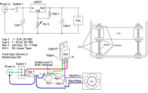
This will allow for perfect speed control. Using just a potentiometer will work at first but wont last and last. You wont get good speed control and using lower volt DC adapters for speed control is silly. Don't do it, build it right.
Also checkout this handy link: http://www.stirstarters.com/instructions.html
If you like DIY then build one if not just order one from here, it is much easier and only marginally more expensive than parting and building it yourself.
Cheers to happy yeasty beasties!
Help this fool
 to build double stir plate using this circuit x2.
When I connect two of those on same power supply, only one pot is working and both vents are working on same speed??
this is what I did

Just finished my DIY stir plate, thanks for the instructions!
I think i'll celebrate by making a yeast starter tonight
I just built my stir plate using the solderless method -
View attachment ImageUploadedByHome Brew1418009025.654552.jpg View attachment ImageUploadedByHome Brew1418009052.525808.jpg
View attachment ImageUploadedByHome Brew1418009025.654552.jpg View attachment ImageUploadedByHome Brew1418009052.525808.jpg
Argg...sorry to bug esp since someone has probably asked this in this thread. So I built the box without the circuit that helps regulate the power. My potentiometer is basically functioning as an on/off switch. I think it is an SSR that I need? Is that right? I know there are ways to build one, but could I just buy one and add it to what I've already made?
Similar threads
- Replies
- 9
- Views
- 2K
- Replies
- 2
- Views
- 2K
- Replies
- 0
- Views
- 1K
