List of PJ Electrical Diagrams

Homebrew Talk - Beer, Wine, Mead, & Cider Brewing Discussion Forum

Help Support Homebrew Talk - Beer, Wine, Mead, & Cider Brewing Discussion Forum:

This site may earn a commission from merchant affiliate links, including eBay, Amazon, and others.
You can if you like, but there's no requirement for it, though I'm not sure what you mean by "requirement". This is something an experimental panel you're building yourself, so there's no requirement to do anything any specific way.

Kal


Thanks. Just wondering if it's needed to keep the component safe.


Sent from my iPhone using Home Brew
 
Nothing wrong with fusing absolutely every component (as some people do), but I feel it's overkill. It's a personal choice.

Kal
 
I have it wired, it works fine! The Overload Protection 2P+N Earth Leakage Circuit Breaker AC 230V 32A gave me a little issue! The other problem is the Auberins SYL-2352 is reading 55F lower than the Floating thermometer. I see there is a way to adjust the reading but are the RTD sensors the way to go? Or is it caused by location of thermocouple from element?


Sent from my iPhone using Home Brew
 
ImageUploadedByHome Brew1406033163.387612.jpg
This is the diagram they sent me on how to wire the Overload Breaker.


Sent from my iPhone using Home Brew
 
Are there diagrams like this for Gas setups? Looking to Add Asco Valves to my Brutus 10 Clone and want to run them with love tss2-21 switches. I have 2 pumps I will manually start and would like to have lights on at each pump and burner when it is active. A kill switch would be Cool as well....Thanks in advance for any input!

:mug:
 
The rheostat connected to the SSVR controls the percent of power delivered by the SSVR to its connected load. The SSVR is not expecting a variable voltage. It does not work that way.

Regarding using a PID along with the SSVR, I have no idea. In the diagram it is only controlling the rate of the boil.

Here's my control panel incarnation that I'm in the process of building which uses a PID (with relay outputs) to control an SSVR.
 
So I'm trying to electrify and set up in my basement (which has running water opposed to my shop which has a tank of water) and the basement has two 30 amp circuits running to it. One for dryer and one for water heater which is no longer in use.

I want to have a 240v element in each of HLT and BK. I'm trying to decide on HERMS and RIMS - I have a RIMS more or less available, would still have to purchase the HERMS coil. One 120v pump at present and debating on getting a 12v pump for RIMS and/or possible HERMS or spring for another Chugger or such. Still also deciding on BCS, Kal's, arduino, etc..

Lots of questions there, but first question is about the two 30 amp circuits. Can I run those into the panel rather than a 50 amp circuit, should I want to run both elements at once? I could install a 50 amp, but it would cost me the Spa panel and gfci breaker and about 40' of, I assume expensive, 50 amp cable, and 50 amp main circuit board breaker - vs. a couple gfci 30 amp breakers. (not an electrician but comfortable working with it - wired a few houses that passed inspections). I assume there is no problem doing this but thought I should ask what others would do.

Would like to just spring for a kit but due to budget, have to start slowly. /jd
 
I would say You only need 30amps since you'll not be using the HLT while boiling.
I use a 30amp circuit to a selector switch to active either contactor.
hope this helps.. Good luck.


Sent from my iPhone using Home Brew
 
+1 on what Clankenbrew said. There's a few PJ diagrams with a selector switch to select one of two elements, for the specific reason you bring up. Since the HLT is use before the BK, two different steps, no need to have them seeing power at the same time. Since you have a budget, this would be cheaper since you won't need a gfci for each circuit.
 
I think I've read through 500 posts. I have found similar diagrams to what I want to accomplish however, I am wondering if anyone has actually built an very similar or identical controller? If so, I would love a diagram and/or a photo of the inside of your final product.

What I want to build is a single PID (2352) controller to trigger my 240V/16A BoilCoil installed in the HLT. I also want to be able the manually switch a single pump on and off. An E-Stop is fine but not necessary (or maybe it is). A main on switch for the entire box would also be desirable.

Looking forward to any input on your similar setups!


Sent from my iPad using Home Brew
 
Does anyone have a diagram for switching between an Auber 2352 and their new controller with the rotary control? Id like to use the 2352 to get up to my boil and have the alarm but want to switch to the rotary controller as opposed to changing to manual mode.


Sent from my iPhone using Home Brew
 
Does anyone have a diagram for switching between an Auber 2352 and their new controller with the rotary control? Id like to use the 2352 to get up to my boil and have the alarm but want to switch to the rotary controller as opposed to changing to manual mode.

Look at the diagram that I posted in this thread in post #391 It has what you are trying to achieve. It is a diagram that should fit your desired setup.

https://www.homebrewtalk.com/f170/list-pj-electrical-diagrams-382286/index40.html#post6091283

I hope this helps you.

P-J
 
I think that may be what I'm looking for, i plan on using the same element for both, do I need separate contactors still or just switching the trigger to the same contactor?


Sent from my iPhone using Home Brew
 
Hmm. Could I just put a selector switch between the positive ssr output from both the 2352 an the rotary controller and the ssr?


Sent from my iPhone using Home Brew
 
Deece,
This diagram is what you are looking for (I think).

Switch 1 is set up to control the input to the SSR or the SSVR so that only one would be used at a time.

Hope it helps you.

P-J

Auberin-wiring1-a4-4500w-30a-e-stop-3.jpg
 
Deece,
This diagram is what you are looking for (I think).

Switch 1 is set up to control the input to the SSR or the SSVR so that only one would be used at a time.

Hope it helps you.

P-J

P-J, I have a similar setup with a PID and a rotary knob, but would like to use the same SSR to control my element. Space is a concern in my salvaged control panel and so I'd like to use only one SSR and switch control of the element between a PID and a hacked PWM dimmer from here: LED Dimmer PWM Hack. The dimmer does not require an SSVR and can output an appropriately pulsing DC signal with the change of one capacitor.

I'd like to use my two-way selector switch to change control of one common SSR between either of the two control sources. Would it be as simple as using that to select the positive signal to the SSR between the PID and the PWM? Is it ok to have both negative wire leads being sent to the SSR unabated and simultaneously and only switch the positive signal? Or would I have to add some extra contact blocks on my switch and switch the negative signal as well? I have a slick Eaton M22 two-way switch with stackable contact blocks and have the flexibility to expand it to control more than one signal.

Thanks in advance.
 
P-J, I have a similar setup with a PID and a rotary knob, but would like to use the same SSR to control my element. Space is a concern in my salvaged control panel and so I'd like to use only one SSR and switch control of the element between a PID and a hacked PWM dimmer from here: LED Dimmer PWM Hack. The dimmer does not require an SSVR and can output an appropriately pulsing DC signal with the change of one capacitor.


I'd like to use my two-way selector switch to change control of one common SSR between either of the two control sources. Would it be as simple as using that to select the positive signal to the SSR between the PID and the PWM? Is it ok to have both negative wire leads being sent to the SSR unabated and simultaneously and only switch the positive signal? Or would I have to add some extra contact blocks on my switch and switch the negative signal as well? I have a slick Eaton M22 two-way switch with stackable contact blocks and have the flexibility to expand it to control more than one signal.


Thanks in advance.


That is actually more what I'm trying to accomplish as well just didn't word it correctly. Only difference being i want to use Aubers new rotary controller instead of the dimmer


Sent from my iPhone using Home Brew
 
I have 2 Honeywell S8610U3009 Intermittent Pilot controls, a asco 8210g2 gas valve, a Honeywell vr8300 valve and a Honeywell vr8200 valve. I have 2 love tss2-2100 controls and a Auber SYL-1512A control. Does it matter what kind of transformer I get? I planned on putting the loves on the HLT and MLT with the Honeywell valves and spark ignition. I'd like to use the auber for only a temp gauge either on the BK or at the exit of my chiller. I have no pilots yet but plan on ordering them soon. Would it be hard to use the asco valve on the BK and have it ignite by push button on the control panel? what other parts would this require and is there a diagram for this type setup? Thanks in advance for any replies!
 
P-J, I have a similar setup with a PID and a rotary knob, but would like to use the same SSR to control my element. Space is a concern in my salvaged control panel and so I'd like to use only one SSR and switch control of the element between a PID and a hacked PWM dimmer from here: LED Dimmer PWM Hack. The dimmer does not require an SSVR and can output an appropriately pulsing DC signal with the change of one capacitor.

I'd like to use my two-way selector switch to change control of one common SSR between either of the two control sources. Would it be as simple as using that to select the positive signal to the SSR between the PID and the PWM? Is it ok to have both negative wire leads being sent to the SSR unabated and simultaneously and only switch the positive signal? Or would I have to add some extra contact blocks on my switch and switch the negative signal as well? I have a slick Eaton M22 two-way switch with stackable contact blocks and have the flexibility to expand it to control more than one signal.

Thanks in advance.
Well I wish you success with your desired mission.
 
Well I wish you success with your desired mission.

P-J, should I be switching on and off the positive signal wire only or should I switch the negative signal as well? The negative signal is like a ground right and doesn't have power normally in a DC circuit, correct? The positive signal is the power carrier in a DC circuit.
 
P-J, should I be switching on and off the positive signal wire only or should I switch the negative signal as well? The negative signal is like a ground right and doesn't have power normally in a DC circuit, correct? The positive signal is the power carrier in a DC circuit.
Sorry. I'm not at all familiar with your LED Dimmer unit.
 
I just want to thank you guys, P-J and Oatstraw, for making the diagrams and compiling all of these diagrams in one location. I've been brewing for a couple of years and have gotten a lot of interesting ideas from this forum, but this thread has been the most helpful of all. I am currently building an electric brewery in my basement and these diagrams are what gave me the ideas and confidence that I can build this.

I'll try to post some pics once the brewery is completed, probably in the next month or so.

Cheers! :mug:
 
thanks so much to PJ and others for this thread. Very helpful. ( -- had question on my electrical system but seems too far off topic so deleted it. )
 
I'm not an electrician, but I'm 99% sure this is correct - the neutral and ground are bonded at the service entrance. If your breaker trips right away, then you either have a bad breaker, or it's not wired correctly. Post a picture of your spa panel wiring.
-Kevin
 
I'm not an electrician, but I'm 99% sure this is correct - the neutral and ground are bonded at the service entrance. If your breaker trips right away, then you either have a bad breaker, or it's not wired correctly. Post a picture of your spa panel wiring.
-Kevin

Thanks Kevin - I didn't see your response so deleted my message above as off topic or at least out of the realm of thread maybe. I had an electrician tell me that the breaker shouldn't trip in that situation - all load wires disconnected from it. So we think it is a bad breaker. Trying to get it returned. Still got lots of other stuff to do on the electrification so hopefully won't hold me up. Thanks again, Jim
 
So just making the jump to electric. I am doing BIAB. I'm wanting a 5500w element with a pump for recirculating mash, pid for mash, e-stop and a potentiometer for boil control. Really don't want to have to go to manual in the pid for boil control. I'm sure PJ has a diagram here for it. Can anyone direct me? Thanks a bunch! Nick
 
Why do you not want to go manual for the boil? If you've got 1 element, then having 1 PID seems easier than a PID and a potentiometer and what will inevitably be a switch to pick between the two...
 
Well I already have a pid from auber and it dosent have manual mode. I really didn't want to buy another one. The one I have works fine so I thought I would just add a seperate boil control


Sent from my iPhone using Home Brew
 
First off let me say this is my first post, but I've been scouring this site for a very long time. I've built a brew stand from the wonderful threads on here, and now I'm looking to build my control panel. I've been searching through every thread I could find on wiring control panels and I have seen tons of amazing PJ schematics. Many were very close to what I was trying to do but not exact. I used what parts I could to build what I'm hoping will be my final product and I'm wondering if PJ, you or someone else on this thread could check my work?

I have two Steelhead pumps, a 1500w 120VAC element and a pair of Auberin PID's. I would like one PID to control my element which will be used to maintain temperature in my HLT while I use one pump to flow through my HERMS. The other PID will be used to monitor temperature as I flow out of my MTLT and I may add a 3 way switch to toggle to a boil kettle probe to check status on the boil. as it's ramping up. I threw in a couple indicator lights for system power and element firing. I'm looking to run this from either a 15A or 20A circuit (probably needs to be 20A). Any suggestions/advice would be greatly appreciated!

Also attached is a photo of my current brew system minus my HLT. Couldn't have done any of this without the help of this forum!

JHM 2 PID, 2 Pump, 1 Element Control Panel.png


JHM Brew Stand.JPG
 
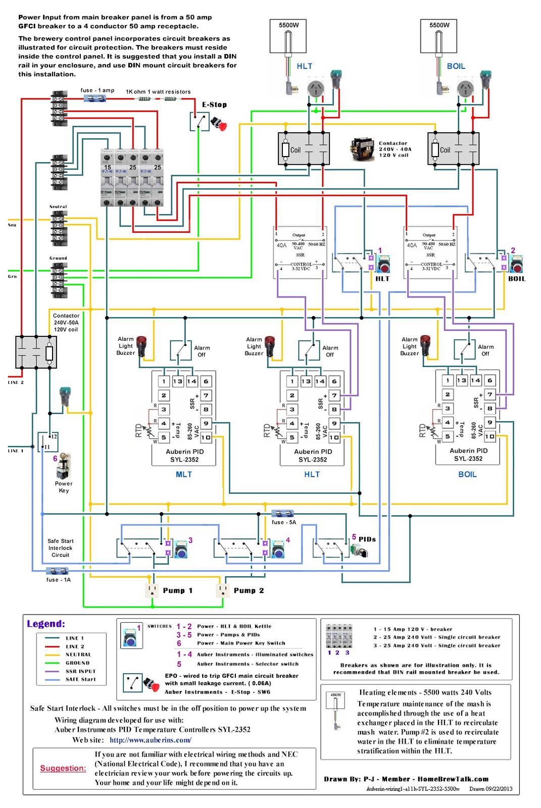
I am basically following this diagram from PJ I found somewhere and I liked the idea of the Safe Start Interlock. I'm trying to use what I have in stock and have a question about switches #1-5. I have 3 position selector switches in stock - sort of based off Kal's site. Question is - I have switches with two NO contacts ea. If I understand correctly, it looks like these switches in the attached diagram use one NO and one NC contacts ea.? Or will my 3 position switches with two NO blocks work? If not I can order some NC blocks and switch 'em out.

There may be better diagrams to use for my purpose. I have two 5500 watt elements for boil and HLT. I have a 4500 watt run at 120 volts for a RIMS so 1100 watts or so. I sort of wanted option of being able to run the two big elements at same time - so using a 50 amp service. Not sure I will yet, but wanted option. I've found another diagram with RIMS that I'm sort of adding into this one..

I want to be able to use two pumps for various purposes. So manual selection is good. First attempt at a panel so advice most welcome.

Auberin-wiring1-a11h-SYL-2352-5500w.jpg
 
If you're trying to follow that diagram, you'll need a NC block for each switch - Power has to run through each switch (showing it's 'off' or in 'normal' state) before it gets to the contactor relay switching line.
 
Thanks BadNews,

Maybe I'll shop around on the various diagrams and simplify a bit until I understand the PIDs and system better. Then I can play around with fancy switches. /jd
 
Any system you want that has a safe-start, regardless if you use the P-J technique or the Kal technique, will require NC blocks on the switches. The whole point is that the initial startup power has to flow through each switch in series before getting to the contactor to fire it up. If any one of the switches is "on", then the NC block is "open" and you have a break in that circuit, therefore the contactor won't get power and it won't turn your panel on.

As for looking at a bunch of diagrams and working through them so you have a strong understanding of how things work and how you want to run yours - absoloutely a great idea!
-Kevin
 
Thanks again Kevin. Last night I figured out the switches - how the contacts stack, the NC and NO workings, etc. The diagram I'm following now is a PJ RIMS one with 3 PIDS which I have already. It doesn't have a 50 amp contactor so I worked that in anyway for future enabling the safe start interlock when I finally get around to ordering some NC contacts.

This diagram has a stacked NO contacts RIMS pump switch - so the pump must be on before the RIMS element will fire off. It also has a 240 volt RIMS element that I've adapted to a 120 volt element for my setup. All I have left to do now is wire the PID to SSR wires and the temp sensors and I'll be able to test, provided I get that replacement 50 amp GFI breaker soon. (First one was bad on delivery).
 
Could any of the experts here help me with the drawing below?

I intend to run a twin element Kettle as shown. Each element has it's own 20 amp breaker.

I will also be adding a PID/SSR to control a HLT.

Due to amp loading limitations, I need a selector switch to select between powering the HLT element or the second kettle element. One element on the kettle could always operate so it would be constant.

That way I can start heating the first runnings while doing the first & second batch sparge.

I know that my setup is not ideal but there isn't a practical option for dropping a dedicated 240v 60a circuit in my detached garage. Plus, this is more portable if I ever moved.

Auberin-wiring1-a4-simple-1.jpg
 
Back
Top