How To: BrewPi LCD Add-On

Homebrew Talk - Beer, Wine, Mead, & Cider Brewing Discussion Forum

Help Support Homebrew Talk - Beer, Wine, Mead, & Cider Brewing Discussion Forum:

This site may earn a commission from merchant affiliate links, including eBay, Amazon, and others.
Could anybody please repost this picture from page 16?

Trying to figure the rotary encoder wiring out with not much success... I don't understand where the resistors and capacitors go, neither the PFET...

Thank you!

this is a good post of the wiring you need, the pink wires are the ones that are for the rotary encoder.

https://www.homebrewtalk.com/showpost.php?p=6813239&postcount=191

and this one shows the pfet having been added its very small, not sure my fat fingers would be able to hold that.

https://www.homebrewtalk.com/showpost.php?p=6694644&postcount=104
 
this is a good post of the wiring you need, the pink wires are the ones that are for the rotary encoder.

First of all, the last thing ANYONE on these forums should be doing, is holding up MY work as an example of what TO do.

Second, they're not PINK, they're WHITE!! (cough!)

In other news... crappy diode and/or solder - replaced and moved the first diode elsewhere, and all working again. HUZZAH!
 
I just ran through the entire thread looking for broken image links and there's just the one.
The reference to hooking up the encoder switch leads me to believe the image I posted was this one.

shield_wiring_newest.jpg

Might as well put the latest/greatest shield schematic in as well...

BrewPi_LCD.jpg

Cheers!
 
trippr, I'm still confussed and discombobulated by the cool/heat LEDs. If the anodes are tied to the 5V rail via the resistors, (and the cathodes to ground), then aren't the LEDs going to be always on (as mine are)? Shouldn't they be coming from pins 5 and 6?

Also (bear in mind, you're dealing with an idiot here!), when it comes to the backlight dimmer, it's either PFET through the diodes and then to LCD *OR* just to a 2N2906 transistor (thereby eliminating the diodes)?
 
You weren't around when this was all fresh, so you've missed some stuff.
In this case, you need to see this image

ac_power.jpg

and this one for context

minion_twins.jpg

My design puts those switches in between the LEDs and the shield signals.
Should be evident what's going on, but the bottom line is the cathodes are either grounded or connected to the same AVR IO signals that switch the relay channels...

hth!

Cheers!
 
Thanks everybody for your time, should be able to wire everything now ;-)
 
Should be evident what's going on, but the bottom line is the cathodes are either grounded or connected to the same AVR IO signals that switch the relay channels...

hth!

Cheers!

It does. Works like a charm now.! I was under the impression the digital pins sent a 5v signal when they were activated (hence ye olde beginner Arduino tutorial!) so had assumed the ANODE was tied to the IO signal, not the cathode. Seems wrong in my head (not saying much there) but it works, so amma gunna STFU! :ban:

Now just need to wire in the PNP transistor I just picked up for the backlight auto off (since let's be honest, who needs a bright blue beacon on at all times!?) and I am DONE! (But will likely break something in the process, haha)
 
Got my prototyping board setup to use lcd and rotary encoder. Letting her run overnight to see if I have the same problem others are having with lcd issues. Then I'll setup the pnp transistor for the backlight. Then onto setting it up with a pro-mini with bluetooth. And I'll have me a minion with lcd finally.

My main issue for taking this long was my RadioShack has been out of 33k resistors.

View attachment ImageUploadedByHome Brew1430607544.669431.jpg
 
33K? What are those for?

The "SI Option" in my schematic uses 33 ohm "series damping" resistors to slow down the edge rate that the shift register sees on the critical inputs.

But as I mentioned quite a ways back, I've found it isn't necessary. Won't hurt, but I wouldn't wait on parts to put that in...

Cheers!
 
Added door features just to see if that can scramble her.
View attachment ImageUploadedByHome Brew1430612140.793228.jpg

And I've got wires of all different lengths and sizes going all over the place. Hopefully I won't see any scrambling. I'm using 1 less resistor than your schematic calls for. And for right now I'm using 2-3 less capacitors than in your schematic. But that's only because I'm testing. I intend to add them back to the pcb layout.

Looking for something to hookup to the relays to use mains voltage to see if that affects the lcd.

EDIT:

Not that it matters but I'm using a 100k pot in place of the 10k because it's what I had.
 
You could start with a desk lamp.

It's funny, there have been folks who didn't even have to have AC loads hooked up that scrambled the LCD when a relay switched. Then someone recently went with the I2C LCD - and that scrambled - which pretty much rules out the entire shift register and a good chunk of the shield as the root cause.

I was never able to have mine crap out even with fridge compressors on the cold relays. And no real idea why...

Cheers!
 
33K? What are those for?


The "SI Option" in my schematic uses 33 ohm "series damping" resistors to slow down the edge rate that the shift register sees on the critical inputs.


But as I mentioned quite a ways back, I've found it isn't necessary. Won't hurt, but I wouldn't wait on parts to put that in...


Cheers!


I meant 33ohm. And there were other parts they were missing too. Mainly ceramic capacitors. But I managed to dig up enough.

So you mean there aren't supposed to be any resistors between the arduino and the lcd? Every other schematic I've followed had some value of resistor on the 3 lines coming from the arduino. Or so I thought.

View attachment ImageUploadedByHome Brew1430612684.687723.jpg

I built this one following a post from the brewpi forum a long time ago.

It's using 10k resistors but it never worked right so I threw it to the side. I left the LCD stuff alone since it seemed everybody was having issues with garbled displays. till it seemed that you created a better solution with less errors. So I followed that.
 
Hmmm. You know what? I did get 33k resistors... And it isn't making any difference as you can see in the above pics. Lol. I guess I don't need them at all.
 
That protoshield is way different than the ones I found locally.

The only other shield design I'm familiar with is Elco's rev C.
He had (three) 10K pull-up resistors on the shift register inputs - but when I actually looked at the Uno outputs for those signals it was apparent he must have invoked pull-ups in the pin setups, as the rise times and levels were good.

In fact I was concerned enough about the fast edge rates that I stuck those three series resistors in my schematic and built my first board with them in place. But I scoped the signals with the resistors jumpered and the ringing was inconsequential so I've been leaving them out...

Cheers!
 
Just means my board will be that much smaller. So it's looking like I just need a 10k resistor for the clr line. And a 200ohm for the pnp. 4.7k for the onewire. And the LCD is done. Since my rotary encoder breakout has the 10k resistors on it already I'm golden.
 
As indicated in my schematic, you can actually tie the CLR pin directly to VCC and cut your component count down one more part...

Cheers!
 
It's gonna mean a lot shorter traces and much easier component management. My mini has pin 10 11 and 13 on the bottom right. So I can almost run the shift register straight in line from that to the LCD. Which orients the mini in such a way that the bt dongle can mate right up to it with just a bit of cris cross from the vcc and gnd. And my rotary encoder breakout will be able to just snap right into a 90 degree header pin. The largest component being the LCD means my board can be the same size as the LCD so this is gonna be quite easy I think.
 
Been a long long time getting it together and I still need to add in the rotary encoder when it finally arrives but.... My scrambled display I've actually found something on a very old brewpi thread that it had happened before and it has something to do with the sainsmart relay and the UK (or anywhere else) 230/240v and EMF I've switched the relay to 2 SSRs and touch wood not had any issues with interference.

Obviously those are famous last words and I'll wake up tomorrow and the lcd will be destroyed but at least it's and answer.

Also day_trippr turns out my probe problem was a dodgy probe in the end a manufactured dodgy connection as I cut my dodgy soldering off and wired it through a terminal block and it was still bad but other probes worked fine. [emoji57] my soldering isn't that ****e after all! (No it really is). If you ever fancy sending one of your minions over here for testing let me know!
 
Glad you have everything working, soldering skills and all ;) You shouldn't have any problem wiring in the encoder, it's been covered in the thread if you need any guidance.

Bad probes happen, though having roughly 30 probes around the house I've only had one arrive DOA, and I totally murdered another. For what I've been paying with 3 meter leads I have no complaints wrt probes...

Cheers! :mug:
 
Wow those pfets are small I'll need to find a way to hold those and solder it in place!
 
Wow those pfets are small I'll need to find a way to hold those and solder it in place!

Yeah, I took one look at those solder jobs with those myself and said "bugger that" and went with the PNP transistor. Much easier, especially if starting out since it just needs the one resistor, rather than including the two diodes and tiny fiddly PFETs.
 
No idea where to begin converting this to an eagle file but apparently this is the Rev C Shield.

brewpi-schield-revc-schematic.png
 
So the scrambles display saga continues it is much less of an issue than last time it doesn't scramble when either the heating or cooling turns on, just when the door is opened.

The fridge has no thermostat and I also removed the door light switch because I thought that might have been causing problems.

It just makes little sense to me, unless there is something loose in my wiring.

Although their was an earth cable that was connected to the thermostat that is now loose could if the opening of the door bumped that against some metal would that cause interference?
 
So, there's no functional door switch (so presumably the interior light doesn't turn on any more) but when you open the door, you can corrupt the LCD?

I don't even know where to go with that one :drunk:

The safety ground to the thermostat was likely a stub from the main safety ground which should be bonded to the chassis somewhere not far from the cable ingress. If the thermostat was mounted to the plastic liner it needed its own wire.

I rather doubt a safety ground hanging in the breeze could do anything...to anything...

Cheers!
 
Pretty much, I had wires the light to the SSR to act as a heater but it wasn't overly effective so I disabled it through the settings, I used the SSR as a replacement for the door switch. It does turn on but only when I tell it too.

I reckon it can only be a lose connection somewhere but where (I don't expect and answer to that)

I need to disconnect and pull it all out anyway to wire in the rotary encoder when it arrives so can have a good look then.

It was definitely the relay causing the problems with my first setup the only thing I can think of that could be different in our settups (other than the quality of the soldering) is the voltage?
 
So my wife decided to throw my envelope full of pfets away which is probably a blessing considering how small they are (i'd never managed to get those things attached)

So i figured i'd go the easier fat thumbed way and get the 2n2906, quick question though Amazon only seem to sell in the UK anyway the 2n2906a whats the difference i had a quick look at the data sheet but to be honest i don't know what i'm looking for?

The 2n2906A and 2n2907A use a tighter process technology then their respective predecessors, and are totally compatible in either direction...

Cheers!
 
I justo wanted ro thank you all guys as, after months waiting for a lost rotary encoder, I finally managed to put it all together, pfet included.
 
It's funny, there have been folks who didn't even have to have AC loads hooked up that scrambled the LCD when a relay switched. Then someone recently went with the I2C LCD - and that scrambled - which pretty much rules out the entire shift register and a good chunk of the shield as the root cause.

I was never able to have mine crap out even with fridge compressors on the cold relays. And no real idea why...

Cheers!

I've been running my brewpi for a while as just a temp logger with my ice chest setup, works well. Now I have power issues with my pi, that I wont go into, but basically I cant run wifi and bluetooth dongle at a time on my model B. need a bigger psu. ANYWAYS....

I just got my first scramble after a couple of changes....
Added Bluetooth (proto was wired for it, just not hooked up.
Converted from USB power from PI to 12V 1A wall wart.
Ran out of grounds on the protoshield so I mad a buss bar breakout and moved two of my lcd grounds from the proto to the bus shield.

So I need to take a couple steps back and im starting to think i need to add some coupling caps to my breakout board as well? I have a 5v rail and gnd rail on it.

I just throught it was interesting because I dont even have my relay board connected.

I'm going to first disconnect bluetooth and see if the scrambling still happens. then work my way back to using USB power instead of the 12v wall wart. And then finally moving some of the gnds on the shield around. I'm not an expert my any means into EMF or RF interference or electronics in general, just some observations.

I have the full board made up with everything ready but only the Rotary, LCD, and now Bluetooth attached. No Relay board or LEDs connected.

It worked perfectly fine logging over USB/serial to the pi prior to this. I may try adding a momentary switch to reset the power to the LCD if I cant figure it out.
 
Minor Update

Went to test the voltage and found this to be odd...

Working fine on own. Then when I touch the 5V line on the bus bar with my probe from my DMM in VDC mode, it scrambles. Instantly. This is not even having the ground probe touching anything.

I disconnected the Bluetooth, still the same issue, so doesnt seem relevant. I moved ALL GND connections to the buss board and problem persists. starting to think its a PSU issue? I'm using a 12V 1A PSU from a DirecTV DECA box.
 
Just played around a little bit and the culprit for my scrambled screen was the external power supply. At least its not scrambling like it was when I touched the new bus. I had added some extra decoupling caps to try to separate noise on the bus bar, but didnt seem to help.

Would the on-board voltage regulator be introducing noise?

EDIT.... Messed around a little more and it seems that that with the 5V usb input for power and then putting PIN 2 on the LCD board isolated behind a decoupling cap works. I plugged the bluetooth in on the same side of the cap and it scrambled, moved it over and I havent seen it do it again yet. I'll let it run tonight and see what happens.
 
For info I could never get my display not to scramble when I used the relay, switched to SSRs and I've had no issues at all with scrambling. I think I got a couple of the pqlyt SSRs from aliexpress. On the flip side with my other brewpi which has a relay I just added a small touchscreen LCD onto the RPI and reconfigured the webpage to only show the lcd. The disadvantage of this is that you don't have a rotary encoder to adjust temps and the display is always on.
 
It's been running connected via usb to the pi now for a few days with no issues to the screen. The bluetooth is still plugged in and powered, but no communication.

I get a new PSU for the pi tomorrow, so I should be able to test it powered by itself and connected via bluetooth. But so far, my observation was to make sure there was an additional Decoupling cap between Pin 2 of the LCD and the Bluetooth module. I used a 100n Green Poly cap.
 
Well... got it hooked up now with bluetooth. I get the majority of my scrambling when using the rotary encoder now it seems. Hooked up the Relay board and triggered them on and off and didnt really notice anything. But when using the rotary got all kinds of scrambling. Thought that was interesting....
 
So that's probably a difficult question to answer but I swear I followed these directions to the letter and all I get is white blocks on lines 1 and 2 of the LCD. (Which I assume to mean it's getting power but no signal.)

I built the protoshield twice, once usibg the schematic and assembled my own shield, and the second time using the shield guide that was posted a little later in the thread.

Both had the same result.

My Arduinos work perfectly and all other aspects of the script and the devices are fully functional... I just can't figure out where to start trouble shooting this thing other than checking the connections over and over again, which I've done...

Is it possible that I have the wrong type of LCD? It's a 2004A 20x4, no backpack... I've tried two separate displays.

All the other components are exactly the same...

I'm pulling my hair out over here....

Any help would be greatly appreciated and may earn you a bottle of whiskey barrel aged barley wine....


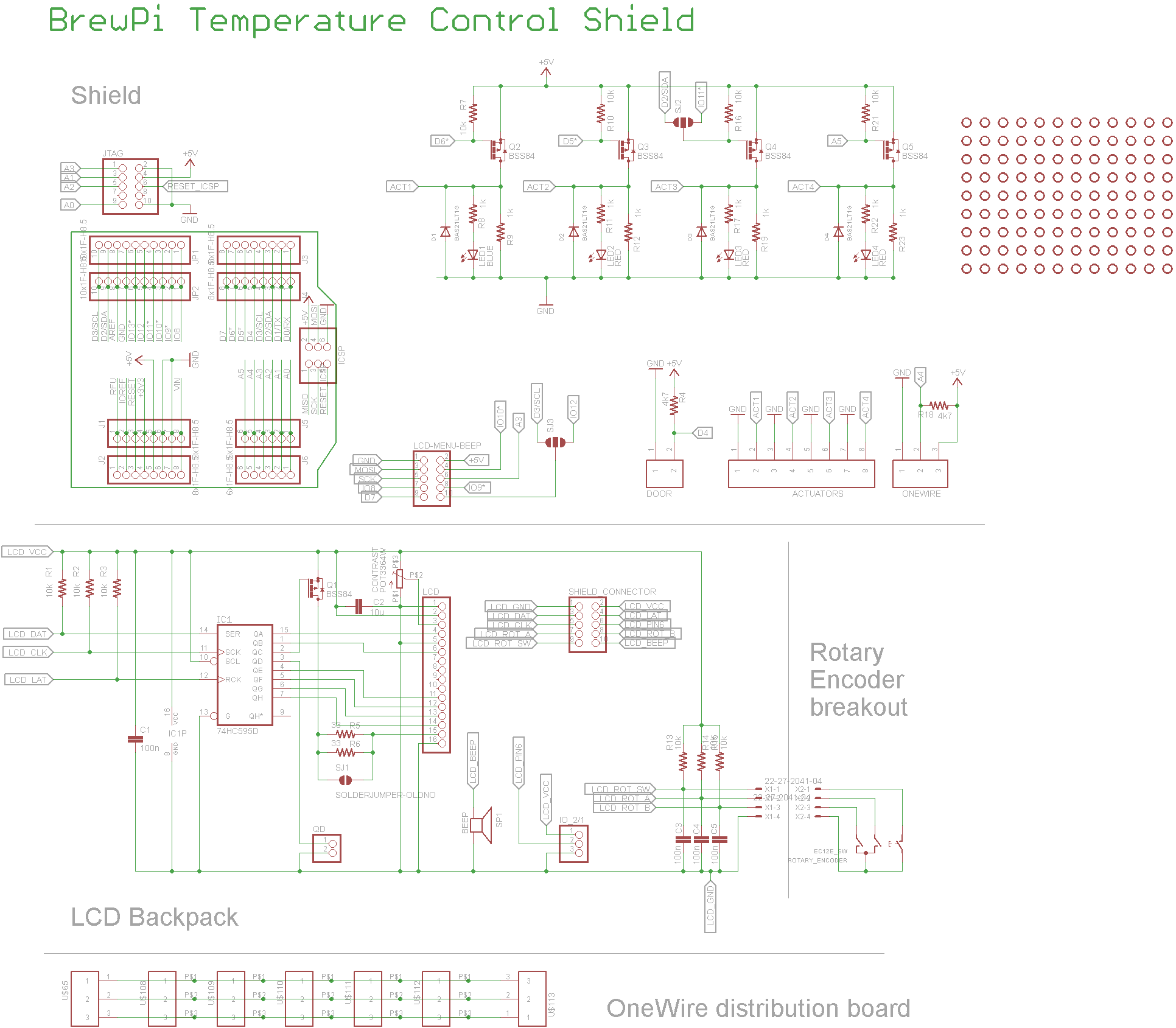
[Revised 1/11/2015 - in second image, corrected proto board wiring diagram LCD pin 15/16 swap]

Here's a procedure to add a 20x4 LCD display to an Arduino UNO R3 in BrewPi service.

Parts needed:

20x4 White-On-Blue LED-backlit LCD display. I got mine here but you can do better on ebay if you're more patient than I was.

74HC595D 8 bit shift register. You can get them here.

10K ohm potentiometer. Any style you like, it doesn't carry hardly any current, and once you have it dialed in you'll likely not change it again, so accessibility "outside the box" isn't necessary. I used a pc mount style.

(2) 1N4001 or 1N4007 diodes (I've used both). Had them on hand but you can get them at Radio Shack if nowhere else.

20 to 30 ohm 1/4W to 1/2W resistor. Radio Shack.

(2 to 4) .1 to 1UF capacitors rated for 10VDC or higher. Radio Shack.

Hookup wire and a protoboard or equivalent.


Notes:

- The first image shows the wiring diagram used. It is a subset of the documentation provided for the rev C BrewPi shield. For example, you'll note the 10K pullups for IO10, 11 and 13 are missing. That's because the current BrewPi code configures those Uno pins as push-pull, so no pull-ups required.

Also, it's missing the function to turn off the LCD backlight after 10 minutes (from the last push of the rotary encoder switch). That's because I don't have the switches yet so I wouldn't be able to wake the display back up, and I didn't have any p-channel FETs handy. I'll be adding that and the wiring for it once the switch arrives.

- Pin 10 of the shift register can be tied directly to VCC, or optionally through pretty much any resistor value you have handy if you prefer.

- Pin 2 of the 10K pot is the "wiper" pin.

- The second image shows the wiring on a small protoboard. I re-did my original to make it easier to photograph (and hopefully follow). Note that pin 1 of the IC is in the north-west corner.

- The third image shows the back side of the LCD wired to the protoboard. Might come in handy.

- The last image just shows the whole mess all together and running using a Bluetooth interface to the host RPi.

Any questions please feel free to ask here.

Cheers!
 
Last edited by a moderator:

Latest posts

Back
Top