How To: BrewPi LCD Add-On

Homebrew Talk - Beer, Wine, Mead, & Cider Brewing Discussion Forum

Help Support Homebrew Talk - Beer, Wine, Mead, & Cider Brewing Discussion Forum:

This site may earn a commission from merchant affiliate links, including eBay, Amazon, and others.
So, not being able to determine where the short was I decided to try again with new components. During the test I noticed the display scramble when the keezer compressor kicked on. I grabbed a 2.2uf 160 V cap I had and soldered it onto the uno's power jack. That seems to have taken care of the scrambling when the keezer kicks on. Now if it will stay stable I can put it in the box.
Well that didn't take long. Same issue. I'm starting to think my cheapo uno can't handle the load of powering the lcd.
 
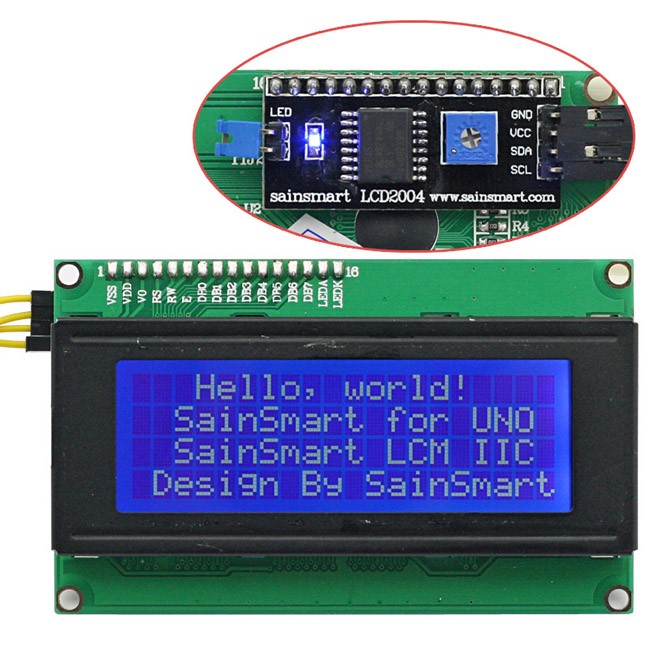
I've been following this thread for some time, and finally got all the components to build the shield. The issue is that the 20x4 lcd (SainSmart), came with an i2c module soldered to the back.

I've pretty much have the shield done. Hopfully not too dumb of a question, but can I just leave that module on, and solder wires to the 16 pin pads?

Thanks
-Mike
 
There's a guy that came up with a way to use i2c on the brewpi forums. doom something I think. check it out
 
Sorry, perhaps I should have more precise. I don't want to use the I2C, as I have the shield done to be used without it. Question is, can I leave that soldered modual on and solder wires to the pads, or do I need to unsolder the module to use it.

Thanks
-Mike
 
No. basically everything you've built into your shield to handle the lcd is more or less already on that board. when you add power anywhere to a circuit, unless it's protected by a diode, it will energize the entire circuit.
 
If you want, I'm switching my displays over to I2c. so if you want to trade all mine are white on blue
 
Thanks wbarber69, that is what I kind of thought. I'd be happy to swap with you if you are in the Seattle area. If not, I'll try to remove the module. I'm much better at soldering then un-soldering, only have the copper strip stuff.

If you want the module after it is removed, please let me know.

Thanks again
-Mike

Is this the LCD display in question?
02_1.jpg


If so, it should be a fairly easy task to remove the I2C back-pack, which will free up the parallel port...

Cheers!
 
Yes, that is the one. I'm picking up a solder sucker tomorrow, which should make it easier.

Thanks
-Mike
 
Finally had a window open where my Brewpi BT minions weren't tied up and I had the free time to upgrade them with the rotary encoder and blanking FET.

Wasn't all that keen on performing this surgery because those skinny Dupont wires tend to break off at the switches when opening these little dudes up, but it had to be done eventually.

First minion anesthetized, opened up, and FET installed.
View attachment 295358

It's alive! Encoder location is a bit tight but its totally usable.
View attachment 295359

Repeat twice more and the gang is up to snuff...

Cheers!

Hey day_trippr, I was just wondering what the dimensions of those enclosures are and where you got them? I've been looking to get a new enclosure and I really like the look of yours.
 
Sorry if this was covered, I did a search but didnt see anything. I'm a total newb to this but managed to get brewpi up and running and now the LCD working on a breadboard. I have no load on the brewpi currently, but the display will scramble after a certain amount of time (not sure how long as it happens overnight). Any ideas?
 
Sorry if this was covered, I did a search but didnt see anything. I'm a total newb to this but managed to get brewpi up and running and now the LCD working on a breadboard. I have no load on the brewpi currently, but the display will scramble after a certain amount of time (not sure how long as it happens overnight). Any ideas?

There are tons of references to this issue throughout this thread. I personally discovered that mine scrambles when the compressor on. So I added a capacitor to the power input on the uno which solved that for me.
 
wbarber69 hates me for this, but the only thing that scrambles my displays is a good blast of static.
My LCD-equipped minions will run for weeks without a corrupted display - and they're actually switching loads.
But they're in the basement where static is never a problem.

Upstairs, though, with rugs everywhere, static can be a *****.
I can croak the test minion in my office pretty much at will during the dry season just walking across the floor and touching a light switch or door handle.

Other than that, I agree the problem most people see associated with relays being switched is likely due to power supply/distribution issues.
Daisy-chaining power and/or ground is a good way to bring that on; distribution should be done using a star topology to avoid current sharing - in particular, the power and ground to relays should travel on their own dedicated connections to the supply.

And it can't hurt to be profligate with decoupling capacitors (ie: in the 0.1uf to 1uf range) plus a couple of storage caps (100uf) strategically located...

Cheers!
 
Yep, I spoke before I thought. Or rather, I posted before I Googled. Based on the wiring diagram on page 2, and having never worked with rotary encoders before, I assumed pins 7, 8, 9 ran to the bottom three pins on the encoder, with the top two unused. Which I tried, and not surprisingly, didn't work. Then I googled a wiring diagram, and read that only one of the pins (either switch side or rotary side) need to be grounded. Turns out the way I have it, both the centre pin of the rotary side, and one of the pins on the switch side need to be grounded (so five wires running from the Arduino instead of three in the diagram). Of course, I'll pull out the soldering iron and jump the two grounds together meaning just four. But still more than the three I assumed. (and we all know what happens when I assume, haha).

But... drumroll... it's all working now! I got the wifi finally (FINALLY!) working on the Pi, the Arduino is now magically (no CLUE why this changed) remembering settings, the display is working, the rotary encoder is working... so all I need to do is make some nicer jumper wires from some ribbon cable, plop this in an enclosure, and I should be good to go.

Big thanks to everyone for their help! (But still think we should put together a board and do a group buy!)

Ubermick, do you mind posting a pic of your wired rotary encoder? I'm struggling with the same issues. Please?

From what I can tell of the schematics when I googled, the outer pins of the bottom side of the encoder, are the rotary pins and the top left bottom one are the PB? No matter how I patch things (with or without one or two extra grounded pins) I don't get the rotary encoder to work.

I'll see if I can dig up some pictures of how I wired things...
 
fwiw, here's a pic of a wired encoder.

encoder.jpg

- black is GND and picks up the middle lead on the 3-pin side, and either one of the leads on the 2-pin side.

- purple picks up the other lead on the 2-pin side and is the "pushbutton" signal to Arduino IO7

- blue picks up one outside lead on the 3-pin side and connects to Arduino IO8.

- green picks up the other outside lead on the 3-pin side and connects to Arduino IO9.

IO8 and IO9 are the up/down signals. If you rotate the switch clockwise the selected value should increment; if it decrements, swap the Blue and Green leads at the Arduino end...

Cheers!
 
fwiw, here's a pic of a wired encoder.

View attachment 322400

- black is GND and picks up the middle lead on the 3-pin side, and either one of the leads on the 2-pin side.

- purple picks up the other lead on the 2-pin side and is the "pushbutton" signal to Arduino IO7

- blue picks up one outside lead on the 3-pin side and connects to Arduino IO8.

- green picks up the other outside lead on the 3-pin side and connects to Arduino IO9.

IO8 and IO9 are the up/down signals. If you rotate the switch clockwise the selected value should increment; if it decrements, swap the Blue and Green leads at the Arduino end...

Cheers!

I where beginning to feel pretty incompetent over here.

Thank you day_tippr! :)
 
I where beginning to feel pretty incompetent over here.

Thank you day_tippr! :)

And now everything is up and running, nice!:rockin::mug: I haven't tried it hooked up to the relays and the fridge (with the compressor) yet though. Crossing my fingers on that one.

Now I'm waiting for parts for the bluetooth option.:)
 
Hello!

Since this week I got my Brewpi up and running. But now I have a problem with it that allot of you have/had too.. The LCD scrambling issue. I read allot of info on this on the internet and Im kind of lost. I found different kind of schematics and I don't know which one is correct and could prevent the LCD from scrambling.

I use this scheme:
attachment.php


I don't know if this is the correct one?

Here you can see Some pictures of my pcb and build:

https://www.homebrewtalk.com/showthread.php?t=466106&page=450
 
Is the OP setup compatible with the legacy branch of BrewPi? I wired up everything last night, using a bunch of old components I had laying around, here's what I used;

-74HC595N shifter register and not the D version)
-Two diodes (not sure if they were 1N4001 or 1N4007)
-A 10K resister off of PIN10 of the shifter register - should be okay.
-A 50ohm resistor in series after the diodes - too much?
-Capacitors in parallel, two .22uf and two 1uf - this should be okay?
-10k pot - should be good.

LCD screen powered up but I did not receive any data to it. I did not adjust the 10k pot.... so curious if this does work for the latest legacy branch or if I need to do something else to the BrewPi software itself to start spitting out the data to the shift register/LCD.

Thanks for any help!
 
Yes, I have an instance running on the latest legacy release and hex file 0.2.10.
Works same as always.

The diodes and 50 ohm resistor are there to drop the LCD backlight voltage.
You could temporarily jumper around those and tie the backlight voltage input pin to 5V for long enough to know if your diodes are backwards or non-functional.

The LCDs I use power up with two lines of white block characters before the AVR firmware kicks in and initializes the shift register and the LCD.
If you don't even see the white blocks, adjust the 10K pot...

Cheers!
 
So wiring it up per schematic, everything should work as is? I'm confused, do I need to reflash something to the arduino or change pin assignments?

Bypassed the diodes and resistors, however not able to see any blocks on the LCD...

Is the shift register my problem? 74HC595N shifter register and not the D version)
 
This implementation is essentially a reduced-complexity version of the rev C BrewPi shield kit, hence it was designed to be compatible with no changes to any part of the BrewPi software package - host code or AVR. All this does is make use of the latent BrewPi AVR code that would go unused if there was no LCD.

There is no functional difference between a 74HC595N or 74HC595D - the former is a DIP package for through-hole use and the latter is an SO-16 for surface-mount use. And while I did say in my original post that I used the D version, I actually used the N package (that was just a fat-finger typo, sorry).

Cheers!
 
Argh! Can get my screen to scramble and also display the two rows of solid blocks. This is wired to OP, so not sure what I am missing... I may try to rewire according to the schematic in post 343 above.

Again, when I get the screen to display the two rows of blocks, there's nothing I have to do with commands? I've tried a power cycle to entire system but no luck either.
 
As I said, you don't have to do anything to any part of BrewPi to get the LCD display (and the rotary encoder) to work. You just have to build your kit correctly, which will result in exactly what the BrewPi AVR code expects to "see".

If you are now getting blocks and scrambled characters you're pretty close.
What you're missing is the coherent transfer of 4 bit characters that control the LCD. This could be due to a failure of one of the four data signals, or the clock signal, or the register select signal, or the ground and/or power connections to the shift register are incorrect.

Serial to parallel conversion is recursive so any single failure will render the result incoherent. You can't get it "partially" working, the whole structure has to be correct to get anything at all out of it.

Follow the plumbing from the Uno through the shift register to the LCD...
brewpi_shield_rev_2p0.jpg


Cheers!
 
Argh! Can get my screen to scramble and also display the two rows of solid blocks. This is wired to OP, so not sure what I am missing... I may try to rewire according to the schematic in post 343 above.

Again, when I get the screen to display the two rows of blocks, there's nothing I have to do with commands? I've tried a power cycle to entire system but no luck either.
Check the integrity of the four wires on D4-D7 on the display. When I was assembling my case, I broke the connections just handling it. When the data from the shift register was interrupted, the display reverted back to two rows of blocks.
 
Alright cool, finally! Got the display working, just a few comments.

Schematic didn't like the tiny 10k blue pot., I used a larger (not Ohm size, but physical) one from radioshack (10k-Ohm Linear-Taper Pot). With this, I barely turn the thing clockwise, before the contrast goes out. Trying to use the smaller circuit board pots was giving me hell of a problem and not data to the LCD screen.

Secondly, I have not put everything in the project box just yet. Just to check the stability, I noticed if I bump wires, it will scramble display. Yes I am aware the shift register goes corrupt very easily. Holding down the reset button on the UNO for 5 seconds and releasing allows display to function normally again. What are some solutions to this behavior?

I also want to say when the sainsmart SSR kicks on, that throws a scramble to the LCD. I believe this was covered in this thread and that the +5V/GND connections to the shift register circuit should be completely separate from the SSR. Currently, I have the +5V from UNO going to a terminal block that supplies the SSR. And from this terminal block (same connection), I run the 5V to the circuit diagram. This is the reason, no?

Thanks again for all the comments!
 
[...]Schematic didn't like the tiny 10k blue pot.

Um...what?

Secondly, I have not put everything in the project box just yet. Just to check the stability, I noticed if I bump wires, it will scramble display. Yes I am aware the shift register goes corrupt very easily. Holding down the reset button on the UNO for 5 seconds and releasing allows display to function normally again. What are some solutions to this behavior?

If merely bumping wires corrupts the display, it's almost surely due to loose connections. If you're using male Dupont terminations plugged into female header sockets, that's a likely candidate. I never use that method as it does tend to be a sloppy connection, while female Dupont terminations make much more solid contact on male header pins.

I also want to say when the sainsmart SSR kicks on, that throws a scramble to the LCD. I believe this was covered in this thread and that the +5V/GND connections to the shift register circuit should be completely separate from the SSR. Currently, I have the +5V from UNO going to a terminal block that supplies the SSR. And from this terminal block (same connection), I run the 5V to the circuit diagram. This is the reason, no? [...]

SSR - or relay board? Which are you actually using?

While there's definitely an association between LCD corruptions and relay switching, to my knowledge the root cause has yet to be pinned down.
Some had the problem without any AC connected to the relays, some only had a problem with a load on the relays, and a few had no problem with relays. And, afaik, those people who used SSRs (or changed out their relay modules for SSRs) don't have the problem.

If using an actual Sainsmart dual relay module, powering the coil voltage rail using a separate wire from the logic voltage rail supply is a good start. And keeping ground and power wires short should help.

Just to make things harder to relate to, none of my BrewPi systems has a problem (and they all use Sainsmart dual relays).

For example, I can use the BrewPi gui to switch relays on and off to my hearts content and never get a corrupted display. For that matter, I can force a relay on via the gui, then pull the relay control wire off the relay board and "spark" it on and off to give the relay a major rattling fit and STILL not corrupt the display (just verified it again). And I'm not doing or using anything out of scope of my write-up, so it's a mystery wtf is going on...

Cheers! :drunk:
 
Thanks for the response. I meant the circuit doesn't like the blue potentiometer. Having one of those soldered in, I could not get any data to the screen. I switched that componenet out to what I picked up for the shack and haven't had a problem since.

Using the dual relay module, and have been monitoring the screen periodically this afternoon, no corruption at all. The cycling of the heater element has not corrupted the display, so everything seems to be working ideally.

Time to put all pieces into the project box.

So, the scrambling problem vanished? Anything you could ascribe that to??

There are many folks using the prescribed 3 pin mini-pot, so either yours was defective or incompatible.
I left out "wiring error" as the fact you recovered with a different pot indicates you can figure out wiring ;)

Cheers! :mug:
 
Think the random scramble in the beginning was due to lose connections that I knocked around while moving the entire setup. Seems to have went away.

My mini-pots are the Bortun 3296 pots, tried two thus far and both did not seem to work.
 
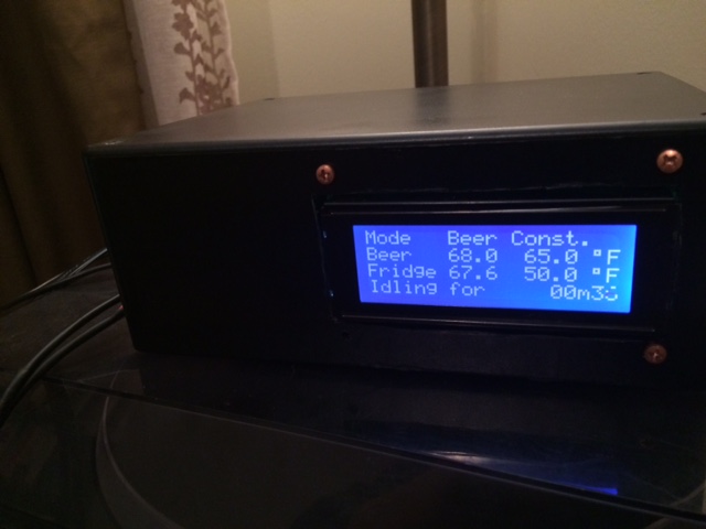
Success, dropped one of the screws for front mount, searching!!!

Don't mind the temps, this was a practice power-up after getting everything in the project box.

Happy to get this wrapped up.

IMG_2866.JPG
 
My linux and soldering skills are a solid 3 out of 10. I'm able to follow directions though. I've put together RaspberryPints with flow meters, so I'm not a complete dolt.

If you had my skills and were going to start the BrewPi build, you eventually wanted to add the LCD screen and the bluetooth option, how would you go about the build? Would you start with the easy wiring diagram on the BrewPi How To thread and get everything running, then build the prototype shield, then get the LCD running, then add the bluetooth option once everything is working? Or would you jump right into the prototype shield and not worry about "testing" it with the simpler setup?

One other question - if I build the prototype shield, it looks like the resistor for the One Wire probes is built into the prototype shield, so no need for connecting the wires together upstream from the shield with a separate resistor. Am I seeing that correctly?
 
Just go straight into the shield (although I never bothered with the Bluetooth) it makes everything a little more plug and play and you don't need to worry that the earth and data are connected to capacitor etc.
 
[...]One other question - if I build the prototype shield, it looks like the resistor for the One Wire probes is built into the prototype shield, so no need for connecting the wires together upstream from the shield with a separate resistor. Am I seeing that correctly?

Yup, you have it right. I wanted all parts on the shield for neatness.
Also, the shield is pretty much a superset of all things BrewPi, so there are functions that some folks might not use at all that they could opt not to install...

Cheers!
 

Latest posts

Back
Top