How To: BrewPi LCD Add-On

Homebrew Talk - Beer, Wine, Mead, & Cider Brewing Discussion Forum

Help Support Homebrew Talk - Beer, Wine, Mead, & Cider Brewing Discussion Forum:

This site may earn a commission from merchant affiliate links, including eBay, Amazon, and others.
Because that's what fixed the devices not getting installed for many a user

Oh, you magnificent bastard! I owe you a pint. Sensors and whatnot are now stored. Hopefully they'll survive a reset this time! Now onto the shield...
 
Okay, so the Arduino itself seems happy now. In it's shieldless configuration, everything seems to be working away. Hooray!

When the shield is added though, it's not seeing the onewire goodies at all. Sees the digital pins (heater cooler action) without issue, but it won't show the thermoprobes under devices. Nor is it showing any of their data in the LCD screen. This is confusing me, since for all of the wiring and shenanigans going on with the shield, the onewire is just a resistor connected to the 5v rail, then jumped onto the shield's analog pin 4, right? The simplest thing in all of it? Checked my work there, and don't see any issue - pulled out the multimeter, and not seeing any issue either. Anyone got any thoughts on that?
 
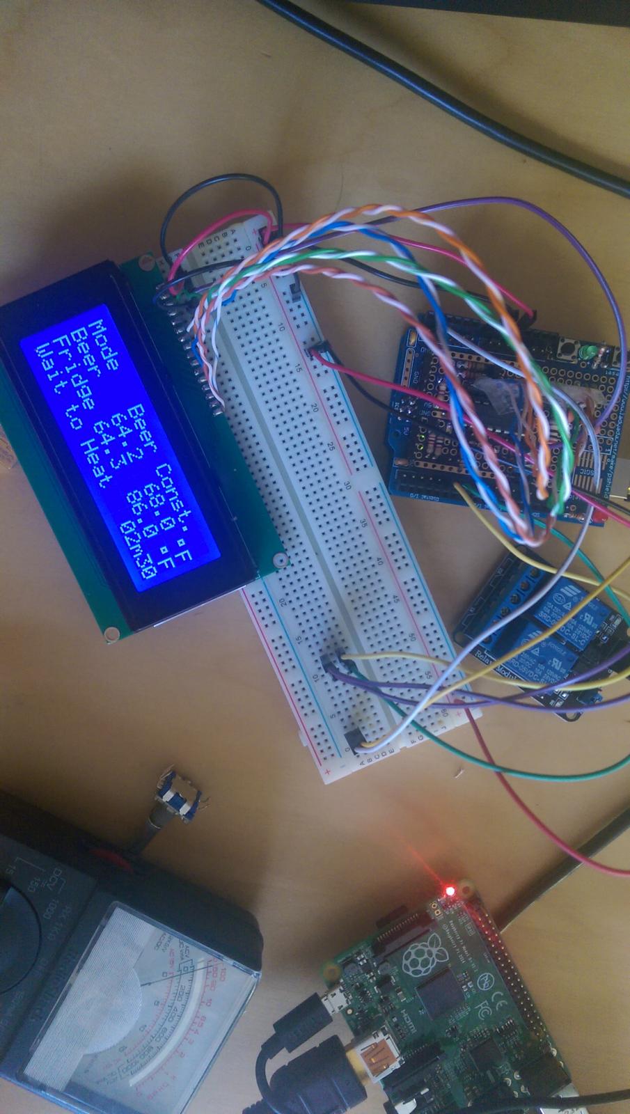
Well, weird. I went over the connections again with the multimeter, this time checking for voltage to make sure there was power getting to that rail. Had a weird needle spike when I measured, almost like the capacitor needed to discharge, and now... and now...

Think it's just the !@#$@# rotary encoder now!

IMAG0192.jpg
 
Oof, rotary encoder is a pain in the buttocks! I assume centre pin of the three to common, and one f the two switch pins there too?
 
Ubermick have you just edited your post? I don't think the rotary encoder attaches to the 10k pot the three wires attach to the capacitors and resistors to the left of the shift register I think. Those are attached to the ground rail, see the diagrams on page 2 I think.
 
Ubermick have you just edited your post? I don't think the rotary encoder attaches to the 10k pot the three wires attach to the capacitors and resistors to the left of the shift register I think. Those are attached to the ground rail, see the diagrams on page 2 I think.

Yep, I spoke before I thought. Or rather, I posted before I Googled. Based on the wiring diagram on page 2, and having never worked with rotary encoders before, I assumed pins 7, 8, 9 ran to the bottom three pins on the encoder, with the top two unused. Which I tried, and not surprisingly, didn't work. Then I googled a wiring diagram, and read that only one of the pins (either switch side or rotary side) need to be grounded. Turns out the way I have it, both the centre pin of the rotary side, and one of the pins on the switch side need to be grounded (so five wires running from the Arduino instead of three in the diagram). Of course, I'll pull out the soldering iron and jump the two grounds together meaning just four. But still more than the three I assumed. (and we all know what happens when I assume, haha).

But... drumroll... it's all working now! I got the wifi finally (FINALLY!) working on the Pi, the Arduino is now magically (no CLUE why this changed) remembering settings, the display is working, the rotary encoder is working... so all I need to do is make some nicer jumper wires from some ribbon cable, plop this in an enclosure, and I should be good to go.

Big thanks to everyone for their help! (But still think we should put together a board and do a group buy!)
 
I'm down if we can get day_tripper to design it with all his free time...
 
lol!

As anyone gainfully employed (which rules out anyone working for any form of government - or financial institution) two weeks of vacation just means the deadlines are two weeks closer :rolleyes: And my primary customer just bombed me with new projects. Great for the revenue stream, not so much for free time.

btw, that reminds me, I never replied to your PM. I actually pulled over the official Eagle files for an Uno R3 shield that I could use as the basis for an Allegro design. I'll probably dabble at it when I'm not too fried from my real work.

But for heaven's sake, don't hold your breath.

One obvious disconnect is I don't need this myownself. I have a wee fleet of hand-wired minions plus a spare already doing their collective thing managing two fridges and a keezer, and don't see further expansion in the offing.

So...

Cheers!
 
My plan is to build my own boards for where and how I need them. So a 1 size fits all board isn't in my future. With different types of arduinos and needing multiple arduinos in some builds and single one-off boards for others I don't think I'll be needing one. But if we did a group buy I'd get a couple just to have. I am planning on building at least one nano minion with lcd and bluetooth. But I'm also planning a dual mini minion to handle rpints as well as brewpi for my kegerator. Once I have things nailed down I'll release my layout files for anyone who wants them.
 
Yeah, completely understandable. (And I feel your pain massively on vacation never being actual vacation, it's just a week frontloaded followed by a week of backloaded work - just started two weeks of paternity leave, and last week was hell - and the emails are already dropping for "when I get back")

And also understand about having functional brewpis already making it a bit of a non priority, since mine is up and working (mwahahah!). But looking through the thread, see plenty of folks who've been having issues, myself included. And know from my perspective, they all stemmed from (well, aside from my own idiocy) my soldering jobs on the wire side. (Missing jumper pins, etc.) So for folks who don't want the spark, or have the $160 or so it costs to have it sent over from Holland, the Arduino based one is the only way to go. Suppose the LCD is just a blingy option though, so not really needed, since folks can just do it all via the web interface. (Sure is pretty tho!)
 
I have managed to get hold of the perfect brew fridge. It's a retro fridge with all the access to make it easy to get probes in etc. a separate top so I can cut in a display and a rotary dial, I just need my blood arduino and protoboard to arrive from China, I'd buy more but like ubermick I could have bought the brewpi for cheaper than its cost me. This time I'm going try the pqlyt ssr s instead of a relay and hope they stop the display from scrambling.
 
Whoops thumb slip---
In the meantime though I second the desire to have an easier to solder board
 
starting a new layout in fritzing. am i to assume that the instructions in the op are up to date with no missing parts?
 
starting a new layout in fritzing. am i to assume that the instructions in the op are up to date with no missing parts?

There were numerous documentation bugs that were fixed along the way, then I added the fet for the LCD blanking. Haven't made any changes since.

You might consider including connectivity for the I2C LCD...

Cheers!
 
Why? Did they actually start actively supporting i2c while I wasn't looking. I know you can tweak the avr code to support it, but I've already got a few tweaks running now and I don't need another headache.
 
Why? Did they actually start actively supporting i2c while I wasn't looking. I know you can tweak the avr code to support it, but I've already got a few tweaks running now and I don't need another headache.

There was a short run in the BrewPi thread, I think, where someone came up with the code mods to make it work successfully. Pretty sure it was the person who shows two-side hard-to-read wiring diagrams in place of actual schematics. It'd be pretty simple - might not have to actually do anything - just make sure there are header pins for the two AVR signals he used for SCL and SDA...

Cheers!
 
Ok, I mistook your post as potentially offering up a board to the unwashed masses, in which case providing the option of supporting an I2C display would be handy for those who'd rather not futz with the shift register.

Yes, it needs code mods, but for those who aren't rolling their own AVR code there's apparently a hex file that works.

But if this is just for yourownself, carry on...

Cheers!
 
i bought these rotary encoders on ebay. they already have 10k resistors on them

Rotary Encoder Module Brick Sensor Development Board For Arduino #100NEW http://www.ebay.com/itm/Rotary-Enco...uino-/310702417391?roken=cUgayN&soutkn=7OSfQ4

I'm nearly back up and running in terms of pulling my display together again.

What is the benefit of have having a 10k resistor built on to the encoder? the product features description is a tad confusing to the like of me.

I just need to order that and a pfet and hopefully i'll have a working display.
 
Day_tripper added to his design 3 10k resistors for the encoder a while back. Something to do with signal noise I think. I was just pointing out that these come with the resistors installed already on a breakout pcb for easy wiring.
 
Ok I see, so you could do away with the long wires running to pins 10,11 and 12 and the left of the centre rails (build_05.jpg page 3 of this thread) ?
 
fwiw, the pull-up resistors for the three rotary encoder signals are accompanied by capacitors, all part of Elco's rev C shield design. The pull-ups are stronger than what you can program into the AVR; the capacitors are there to try to cut down the encoder switch-point noise...

Cheers!
 
Stoopid question regarding the LED panel indicators - decided they'd be nice, so connected a pair of LEDs and... they're always on? Should they not both be off, and only active if heating/cooling is going on? (Positive anodes to the pins as laid out in the shield, and cathodes to ground?)

Ooop, and now my LCD backlight has gone for a walk...
 
Stoopid question regarding the LED panel indicators - decided they'd be nice, so connected a pair of LEDs and... they're always on? Should they not both be off, and only active if heating/cooling is going on? (Positive anodes to the pins as laid out in the shield, and cathodes to ground?)

Hooked up to the same inverted outputs that switch the relays, my LEDS only light when the channel is hot.

Ooop, and now my LCD backlight has gone for a walk...

Might want to fix that ;)

Cheers!
 
Hmm, think I see the problem with the LEDs, when I wired them up per the post on page 2: https://www.homebrewtalk.com/showpost.php?p=6604600&postcount=16

just noticed that the LEDs aren't actually wired to a pin - they're pulling power directly from the central 5v rail, through the resistors, and out to the LEDs.

As to the backlight, found the culprit. My 10k pot quite literally fell apart last night. So now need to get that off there somehow, and replace it without any desoldering tools. FUN! Looks like I might have to make another one...
 
I ordered all the parts to add a lcd screen and rotary knob to my brewpi but decided to just use an old phone instead.

That said I'll be posting the parts in the classified section later today if anyone is interested.
 
Frankly, just gutted now. I was ->this close<- to having this thing assembled, fully working, and ready to go, and then the display crapped out. Made an absolute pig's ear of trying to fix the issue with the trim pot, so had to make another shield, which doesn't work at all.

The amount of money, time, effort, and sanity I've sunk into this is ridiculous now. I wish to @#$# Elko was still producing shields. $50 and this would have been DONE, rather than constantly ordering components, making a mess of various shields, and everything else. Guarantee I've sunk 3-4 times that into this now.
 
Okay. Deep breath. In. Out.

Salvaged what I could, and have it back to where it was before - working, but without the backlight. (And the indicator lights are still permanently on).

Knowing that pin 15 is what supplies power to the backlight, that's gotta be the culprit. Connecting it straight to the 5v rail instead of through the diodes and 20ohm resistor has it lighting up nicely. So clearly there's an issue with the connection SOMEWHERE along that line. Grabbing the multimeter and ohming out the line, there's zero reading across the first diode (going from the 5v rail) so assuming that's blown and replacing it would be in order? (Or could just say screw it, and run 5v directly in there, knowing it'll go pop at some point, hahah)
 
Wire the common for the rotary encoder side to either of the two pins on the other side, then connect that to any handy Ground pin on your shield board.

The other three pins connect as shown here.

247280d1420685923-how-brewpi-lcd-add-shield_wiring_newest.jpg


Don't worry if you can't figure out which of the two encoder pins goes to which AVR pin - just connect them to IO 8 & 9. When you try it out, press the push button and set the Mode to Beer Constant, then when you adjust the Beer Temperature goal you'll see if turning clockwise increases the value or decreases it. If it decreases, swap your connections to IO 8 & 9...

Cheers!

Could anybody please repost this picture from page 16?

Trying to figure the rotary encoder wiring out with not much success... I don't understand where the resistors and capacitors go, neither the PFET...

Thank you!
 
[edited 01/16/2014 - added recommended wire type/size)

The second minion is up and running, so I had time to complete the protoshield build documentation.

The basic scheme supports the One-Wire bus and the LCD display.
Refer to the original post in this thread for links to the larger pieces.

There are also these support options:
- Bluetooth/Serial Module
- rotary encoder switch
- cool/heat panel LEDs

Parts: Starting with what's included in the Arduino Protoshield V6 (latest/greatest) the additional parts required for the basic scheme are:

- 20x4 white-on-blue parallel-entry display
- 74HC595D
- 10K 3-lead trim pot
- (2) IN4007 diodes
- 20 to 30 ohm resistor 1/2W
- 4.7K resistor 1/4W
- I recommend using 24-26 gauge solid, insulated wire

- optional but recommended: 16 pin IC socket
- optional but recommended: extra .1 UF >10V ceramic capacitors (2 or more)
- optional: extra header pins


Add for Bluetooth/Serial Module:
- 1K resistor 1/4W
- 2K resistor 1/4W

Add for Rotary Encoder:
- (3) .1UF >10V ceramic capacitors
- (3) 10K resistors 1/4W

Add for panel LED support:
- (2) 220 resistors 1/4W


Also, I've included a schematic of the AC switching scheme I'm using. This provides independent On/Off/Auto control for the Cool and Heat AC outlets. This uses a pair of 20A rated DPDT On-Off-On switches and a pair of LEDs along with the Sainsmart dual relay card. All of that is optional.


Building the base Protoshield: There is a tutorial for assembling the Arduino Protoshield here. Unfortunately it is for an earlier revision PC board, but almost all of the instructions still apply.

The kit comes with the parts shown in the first picture below.
I used all parts but the two 1x5 headers and one of the 1x6 headers.

Caution: Note which side is "UP" before starting.
The only part that is installed from the BOTTOM side of the board is the 2x3 stacking header (shown at the left edge in the second picture).

Completing the Build:

I prefer not to use Dupont wires with male ends as they need more air space above the board and are intrinsically fragile. I've done this layout so all wire connections use female Duponts.

The kit comes with a strip of 36 header pins which is enough - if you install them where they are needed. If you have extra header pins on hand you can go nuts like I did, but if you're stuck with just the 36 pins in the kit, I've highlighted the 32 pins that need to be present. These pins match up with the jumper wire connection points in the diagram at the bottom of this post.

The IC orientation isn't optimal wrt the Protoshield etch (IC power and ground pins are on the "wrong" sides of the two bus strips), but was to keep the switching inputs to the IC as short as possible as HC series logic doesn't take well to input ringing.

So there it is. Hopefully there's enough here to successfully construct a protoshield, but feel free to post any questions/issues/objections/suggestions here...

Cheers!
this post is the one your looking for post 16 not page 16 note pics didn't show in quote
 
Last edited:
Back
Top