You are using an out of date browser. It may not display this or other websites correctly.
You should upgrade or use an alternative browser.
You should upgrade or use an alternative browser.
How to build a control panel (part 1)
- Thread starter kal
- Start date

Help Support Homebrew Talk - Beer, Wine, Mead, & Cider Brewing Discussion Forum:
This site may earn a commission from merchant affiliate
links, including eBay, Amazon, and others.
PJ, I like your suggestion better than what I have. Despite the label on mine of Extra Low Density, yours has a lot more surface area.
I put together a parts list for my RIMS this morning. PM me if anyone is interested. I don't know how to put together one of those nifty schematics or I'd do that as well.
I put together a parts list for my RIMS this morning. PM me if anyone is interested. I don't know how to put together one of those nifty schematics or I'd do that as well.
pola0502ds
Well-Known Member
- Joined
- Jan 12, 2011
- Messages
- 846
- Reaction score
- 3
The one p-j mentioned is HWD. I have never read about someone using a HWD for there setup. Maybe i missed a thread but is hwd acceptable for a rims tube at 1500 watts or so but not acceptable for say a 5500 watt element for an all electric system?
The one p-j mentioned is HWD. I have never read about someone using a HWD for there setup. Maybe i missed a thread but is hwd acceptable for a rims tube at 1500 watts or so but not acceptable for say a 5500 watt element for an all electric system?
No. It is LWD.
From the description:
Preferred Parts resistored stainless steel elements feature a low watt density design with an outer sheath of Incology® 800 to resist failure from dry firing.
pola0502ds
Well-Known Member
- Joined
- Jan 12, 2011
- Messages
- 846
- Reaction score
- 3
No. It is LWD.
From the description:
The description from the boston website says:
Rheem SP10868LH 120V, 1440W, 7-11/16" HWD Resistored Stainless Steel Heating Element
If you click on the link you provided and then once your on bostons website, go to the Rheem heating element home page, then find the one you listed and the description above is listed.
It says it has a LWD DESIGN but is it really LWD?
OP
OP
kal
Well-Known Member
I haven't read the whole post...is there an estimated cost?
Of pre-built control panels? No. Not yet. We're close however.
Kal
I haven't read the whole post...is there an estimated cost?
I have about $700 into my control panel and $4700 into the build. I only have one PID, so I would think Kal's control panel would be about $900 with the extra parts.
OP
OP
kal
Well-Known Member
You want an estimated cost to built it yourself? I have a complete breakdown of costs in my FAQ. See: http://www.theelectricbrewery.com/FAQ
Read the caveats too - pricing of the parts is in constant flux and will depend also where you live, etc.
All I can do is provide a rought "guestimate".
Kal
Read the caveats too - pricing of the parts is in constant flux and will depend also where you live, etc.
All I can do is provide a rought "guestimate".
Kal
pola0502ds
Well-Known Member
- Joined
- Jan 12, 2011
- Messages
- 846
- Reaction score
- 3
Just as an FYI, I have about 30' of the stainless steel wire rope left over that is used for making the XLR cables if any body wants it. It's $.07 per foot so its very cheap, i'll just give it away if you cover the shipping.
pola0502ds said:Just as an FYI, I have about 30' of the stainless steel wire rope left over that is used for making the XLR cables if any body wants it. It's $.07 per foot so its very cheap, i'll just give it away if you cover the shipping.
I'll take it if it is still available
pola0502ds
Well-Known Member
- Joined
- Jan 12, 2011
- Messages
- 846
- Reaction score
- 3
I'll take it if it is still available
Done deal.

New Kal inspired RIMS brewery being tested. Ran about 6.5 gallons of H20 from 50 degrees from the tap through several rests and eventually mashout at 168. The 1500 watt element worked like a champ. Kal's washer/silicone O-ring setup created a leak free connection to the RIMS tube (supplied by Marcus at brewersequipment). My only hiccup was a bad splice job on one of my pumps that I needed a longer cord on. I'll be replacing the splice with a sealed electrical box. My GFI tripped in a nanosecond when I plugged it in.
hatfieldenator
Well-Known Member
- Joined
- Sep 15, 2010
- Messages
- 493
- Reaction score
- 18
Looks good! Do you have that set up in a basement? How do you vent your system? I assume you're still using natural gas for the boil? Nice work!
Yes, it's set back in an "alcove" that is the foundation for the dinette bump out above.
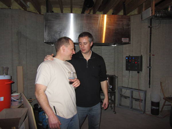
Since this picture was taken I've run the 8" exhaust to the in-line fan, but have not completed the run to the window. It will have a length of flexible tubing at the window so I can take the exhaust manifold out and return it to being a window when not in use.
You can see the 1" NG line coming down the wall to the right of the control panel.
adivito
Well-Known Member
I am planning my setup, and I am just curious why to use both the dpdt mechanical relays, and the ssr's for the elements. Couldnt you get by just using one?
wedge421
Well-Known Member
Yeah this electric brewery setup is 2nd to none. Just amazing stuff and I cant wait to see what Kal will be selling from it!
OP
OP
kal
Well-Known Member
Yes and no. Yes, it would work. No, it (in my humble opinion) would not be safe.I am planning my setup, and I am just curious why to use both the dpdt mechanical relays, and the ssr's for the elements. Couldnt you get by just using one?
Read the "How it works" section here: http://www.theelectricbrewery.com/control-panel-part-2?page=13
To quote:
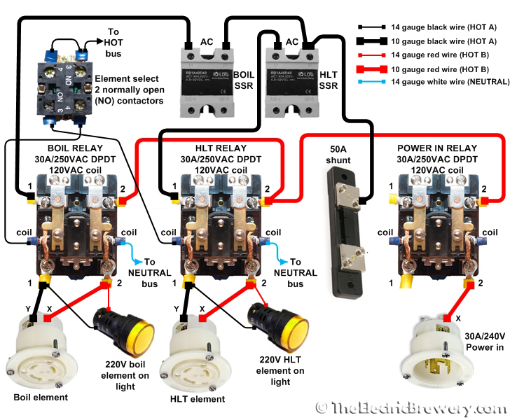
The Boil Kettle and Hot Liquor Tank heating elements are fed from the 120V HOT A and HOT B lines for a total (differential actually) of 240V.
When the ELEMENT SELECT 3 position switch is turned to either BOIL or HLT, the switch energizes either the BOIL or HLT relay coil which in turn allows power to pass only to that one heating element regardless of how the PID controllers are set.
At first glance the BOIL and HLT relays may seem redundant: We use a PID which controls an SSR which in turn tells the element when to fire. So why are the mechanical relays needed at all? Why don't we simply use the ELEMENT SELECT 3 position switch between the PIDs and SSRs instead? The reason is safety: The mechanical relays ensure that there is a complete physical disconnect between both HOT lines and the heating elements when the relay is off. This is important as we will often be working or cleaning one kettle while the other is operational.
Doing something similar with SSRs would require 2 SSRs per heating element (one for HOT A and one for HOT B), but even that would not be 100% safe as SSRs have a small amount leakage current that flows through at all times, even when the SSR is off. SSRs are also known to fail from time to time and when they do, they tend to fail "closed" meaning that heating element stays on. The mechanical relays provide us with the piece of mind that when we've turned the element off, there is no possibility of it coming on by accident nor is any side of it energized.
So why use SSRs at all? Why can't we just use the mechanical relays? SSRs are Solid State Relays, essentially switches with no moving parts so they are able to switch as fast as required, often many times per second. Regular mechanical relays are not meant for this amount of switching as the contacts would wear out quickly. Whenever frequent switching is required, SSRs are used instead as we've done here. The three 30A/240V DPDT relays we use are only switched once or twice during the brewing session so they are being used in the way that they are designed to operate.
Whenever power flows to one of the heating elements, the respective ELEMENT ON 220V pilot light (wired in parallel with the element) turns on letting us know that power is being applied. This is an added safety precaution to show us what is going on. The PID controller may be firing the SSR, but unless the respective mechanical relay is also on the ELEMENT ON 220V pilot light will not come on.
How you chose to wire it up in the end is of course up to you, but I choose to only document what I consider the "right" and "safe" way.
Kal
OP
OP
kal
Well-Known Member
Absolutely everything (eventually). We've got a few things already available, control panel coming up next - hopefully within a week or so. Just waiting for 1 set of last parts (the handles) so that we can take our final product pictures. Other than that it's been ready to sell for about a month. Already sold one as well!Yeah this electric brewery setup is 2nd to none. Just amazing stuff and I cant wait to see what Kal will be selling from it!
Kal
adivito
Well-Known Member
Thanks, Kal I think I have read it some many times, I start to skip parts. One last question, I have 220 volt pumps, would you just wire in another mechanical relay or what do you feel is the best option?
OP
OP
kal
Well-Known Member
The current 120V pumps do not go through a separate relay so no need for a new relay for 220V pumps. A bunch of wiring changes would of course be needed since the pumps would be wired across both hots instead of across one hot and the neutral. You'd likely have to change the 120V green pilot lights for 220V ones too.Thanks, Kal I think I have read it some many times, I start to skip parts. One last question, I have 220 volt pumps, would you just wire in another mechanical relay or what do you feel is the best option?
Kal
Yes and no. Yes, it would work. No, it (in my humble opinion) would not be safe.
Read the "How it works" section here: http://www.theelectricbrewery.com/control-panel-part-2?page=13
To quote:
How you chose to wire it up in the end is of course up to you, but I choose to only document what I consider the "right" and "safe" way.
Kal
Couldn't you wire one SSR to both relays and cut out one SSR? I've been thinking about trying to use one PID for both the HLT and BK. The only other issue would be switching the probes. I'm still pondering that short of unplugging one and plugging in the other. I'd rather the one switch did both.
There probably a safe way to switch the elements and only use one relay, but I don't have enough knowledge yet to figure it out.
OP
OP
kal
Well-Known Member
Couldn't you wire one SSR to both relays and cut out one SSR? I've been thinking about trying to use one PID for both the HLT and MLT. The only other issue would be switching the probes. I'm still pondering that short of unplugging one and plugging in the other. I'd rather the one switch did both.
There probably a safe way to switch the elements and only use one relay, but I'm don't have enough knowledge yet to figure it out.
Just thinking off the top of my head, if you wanted to use only one SSR and still kept the element select switch, you could add extra contactors to the back of the switch to choose which PID controlled the SSR (assuming you used more than one PID). I suppose that would work.
The cost savings of one less SSR but adding extra contactors (about $10 savings difference) I'd rather keep it discrete simple. You'd also likely run out of depth in the panel for the safe start interlock extra contactors required on the same switch as you'd have contactors 3 deep at that point.
I don't see how you could reduce it further to only have 1 relay. The whole point of two relays is to physically disconnect one element while the other's in use for safety.
Sometimes trying to make things simpler just makes it more complex.
")
Kal
Just thinking off the top of my head, if you wanted to use only one SSR and still kept the element select switch, you could add extra contactors to the back of the switch to choose which PID controlled the SSR (assuming you used more than one PID). I suppose that would work.
Kal
I was looking at using just one PID also for the HLT and the BK. Since you're not using both elements at the same time, you're not using the two PID's at the same time either. By using one SSR and two relays, it would appear to my untrained eye that when you make the switch the PID would switch elements also. The only issue is that the inputs wouldn't have switched. I haven't looked into it yet, but it would seem that some type of DPDT switch would accomplish this.
Actually, I'd like to get rid of the PID for the MLT tank, also. It seems to me that all it is a temperature display and there's got to be a cheaper way to display the temperature from that probe. I haven't found one yet.
OP
OP
kal
Well-Known Member
There are certainly a million ways to change what I've done. If you read my FAQ, finding the cheapest way to do it wasn't my goal. Cutting out a few parts would indeed save a few dollars but I feel that it would not amount to much in the grand scheme of things and would make the system less user friendly, less convenient, and depending on the changes, less safe.I was looking at using just one PID also for the HLT and the BK. Since you're not using both elements at the same time, you're not using the two PID's at the same time either. By using one SSR and two relays, it would appear to my untrained eye that when you make the switch the PID would switch elements also. The only issue is that the inputs wouldn't have switched. I haven't looked into it yet, but it would seem that some type of DPDT switch would accomplish this.
Actually, I'd like to get rid of the PID for the MLT tank, also. It seems to me that all it is a temperature display and there's got to be a cheaper way to display the temperature from that probe. I haven't found one yet.
To quote my FAQ:
What were your main criteria in designing The Electric Brewery?
Our all-grain brewery had to meet the following criteria:
- 100% electric for indoor brewing
- Safe, easy, and enjoyable to use
- Not limit the brewer in any way
- Provide for extremely repeatable and consistent results
- Use industrial quality parts that last (all stainless steel, limit the use of plastics)
Note that price is not listed. When we weighed price vs. performance vs. safety vs. convenience, price was considered as the least important factor. That is the complete opposite of what most home brewers do when they put together a brewing setup. For most, price is always the overriding priority and sacrifices have to be made. That's completely acceptable of course as everyone has different needs.
While cost savings was not the primary criteria in designing our Electric Brewery, we didn't (in our opinion) spend money for no reason. Every expenditure was a conscious decision of price vs. quality/performance/convenience.
So by all means use any of the information you like and make as many changes as you like. It's your system after all.
If you read through my build steps you'll see exactly why I chose to use what I did.
If I had to redo it all over again (nearly 3 years later), I wouldn't change a thing. I spent hundreds (thousands?) of hours thinking and designing this system so that I wouldn't feel like constantly changing it.
Kal
wildcatvictory
Member
subscribed
Damn this Electric Brewing! This and the entire DIY forum are going to end up costing several paychecks. Just wait until SWMBO sees the Visa Bill this month. Might have to buy a tent (yet another visa purchase that will be the result of these forums!).
Klaus
Klaus
Sparky
Well-Known Member
Damn this Electric Brewing!
Klaus
Klaus,
Welcome to the DARK SIDE!
Moo-hoo-ha-ha

Damn this Electric Brewing!
Klaus
I wish I had never found The Electric Brewery website. All I can think about now is planning my brewery.
OP
OP
kal
Well-Known Member
I wish I had never found The Electric Brewery website. All I can think about now is planning my brewery.
My work here is done! Muahaahahahaa!!
( ... said while rubbing my hands together in an evil scientist sort of way while Tesla coils arc and snap in the background ... )
Kal
adivito
Well-Known Member
OT but I this rang in my head after Kals comment
Last edited by a moderator:
OK- so I have a new drill press now. I went with a larger version of the one Kal linked in his .pdf version. The only question I have is this.... how the heck did you manage to use it for a large metal enclosure? The distance from the stand to the drill bit is shorter than 16 inches, so I can't get the entire enclosure under the drill to drill the large holes. I assume that those of you who have done this before know how to do this? I tried doing it initially before buying a drill press with my standard drill and ended up breaking the mandrel. Seems like a drill press is the best way to go, but I can't figure out how to get the box underneath and secured tightly so it is safe.
Any ideas?
Klaus
Any ideas?
Klaus
pola0502ds
Well-Known Member
- Joined
- Jan 12, 2011
- Messages
- 846
- Reaction score
- 3
Kshuler,
I didn't do what you want to do but what I did was, i drilled everything with a cordless drill and it worked perfect. Holes were ut perfect with bi-metal hole saws. I have a festool drill and those things can take a beating so I wasn't worried about the situation. If you use a cheap drill then i'd be willing to bet it wouldn't work out that well and possibly burn up the drill.
I didn't do what you want to do but what I did was, i drilled everything with a cordless drill and it worked perfect. Holes were ut perfect with bi-metal hole saws. I have a festool drill and those things can take a beating so I wasn't worried about the situation. If you use a cheap drill then i'd be willing to bet it wouldn't work out that well and possibly burn up the drill.
OK- so I have a new drill press now. I went with a larger version of the one Kal linked in his .pdf version. The only question I have is this.... how the heck did you manage to use it for a large metal enclosure? The distance from the stand to the drill bit is shorter than 16 inches, so I can't get the entire enclosure under the drill to drill the large holes. I assume that those of you who have done this before know how to do this? I tried doing it initially before buying a drill press with my standard drill and ended up breaking the mandrel. Seems like a drill press is the best way to go, but I can't figure out how to get the box underneath and secured tightly so it is safe.
Any ideas?
Klaus
Can you turn the head of the DP to one side so it's no longer above it's stand?
milldoggy
Well-Known Member
Had the same issue, I turned the base, put 2 2x4's under it, then bolted the base to the 2x4. This gave me the clearance I need. Make sure to screw or bolt down your 2x4s to the surface.
Or you could remove the base and bolt directly to a raised platform.
Or you could remove the base and bolt directly to a raised platform.
Had the same issue, I turned the base, put 2 2x4's under it, then bolted the base to the 2x4. This gave me the clearance I need. Make sure to screw or bolt down your 2x4s to the surface.
Or you could remove the base and bolt directly to a raised platform.
Brilliant. Thanks. So basically you just stack 2x4s up until you get the requisite height and turn the base out of the way. Makes sense, thanks. Any safety issues with doing this other than just making sure that the whole thing doesn't tip over?
Klaus
milldoggy
Well-Known Member
If you bolt everything down, you will be fine. I used some lag bolts for the stand to the 2x4 and drywall screws for the 2x4 to my surface. I use one 2x4 for height, but two horitzally for stability.
OK, got the drilling done. thanks for the help. Still need to cut the hole for the heatsink, then can prime and paint. Getting excited!
One thing-
It looks like from the site like the second you switch the element select switch to either the kettle or the HLT the red wire is always going to be energized. Wouldn't it be yet safer to run both the black AND red wires from the main power line through an SSR, instead of just the black one? I understand it would need extra SSRs. I am building a single kettle BIAB setup and RIMS tube. I have 3 SSRs (two 40 amp and one 25 amp) and was thinking of doing it this way, as the RIMS element runs off 120v and the Kettle/Mash Tun runs off 240. Any advantages or disadvantages this way? Am I just being paranoid about having a continuously hot wire all the time?
Klaus
OP
OP
kal
Well-Known Member
I don't really understand the concern: When you flip the element select from OFF to either HLT or BOIL KETTLE, you are telling the system that you want one of those two elements to be energized. You should expect the element to be hot. This puts you, the brewer in control.One thing-
It looks like from the site like the second you switch the element select switch to either the kettle or the HLT the red wire is always going to be energized. Wouldn't it be yet safer to run both the black AND red wires from the main power line through an SSR, instead of just the black one? I understand it would need extra SSRs. I am building a single kettle BIAB setup and RIMS tube. I have 3 SSRs (two 40 amp and one 25 amp) and was thinking of doing it this way, as the RIMS element runs off 120v and the Kettle/Mash Tun runs off 240. Any advantages or disadvantages this way? Am I just being paranoid about having a continuously hot wire all the time?
The red wire isn't energized all the time - it's only energized when you the brewer want it to be with that switch. It's your "ON" switch.
Putting extra SSRs in there doesn't make any sense to me. Why is that safer? Would you put in your hand in there if the element select switch was in one of the two ON positions and the element was cycling on/off periodically? I certainly hope not!
Kal
Yeah, I guess it shouldn't matter. The whole thing will be grounded anyway. It just occurred to me that when the switch is on BK or HLT instead of off, the red wire will be hot the whole time instead of pulsing on and off via the SSR. I just thought it would be nice to not have uninterrupted hot wires the the whole time. If something goes wrong with the grounding for whatever reason you could only get shocked when the element is actually firing instead of just selected to the on position.
Again, I guess it shouldn't matter as the whole thing is grounded anyway. And since usually I check to make sure that things are active by putting my tongue across the two leads, anyway, maybe I am just being overkill.
Klaus
Again, I guess it shouldn't matter as the whole thing is grounded anyway. And since usually I check to make sure that things are active by putting my tongue across the two leads, anyway, maybe I am just being overkill.
Klaus
Similar threads
- Replies
- 10
- Views
- 2K
- Replies
- 4
- Views
- 561
- Replies
- 11
- Views
- 1K
- Replies
- 0
- Views
- 1K
- Replies
- 9
- Views
- 3K