• Please visit and share your knowledge at our sister communities:
  • If you have not, please join our official Homebrewing Facebook Group!

    Homebrewing Facebook Group

Wiring Diagram Sanity Check

Homebrew Talk

Help Support Homebrew Talk:

This site may earn a commission from merchant affiliate links, including eBay, Amazon, and others.
The idea is to have low element power when on during mash temp maintenance in a recirculating direct fired vessel. Less chance of getting the wort too hot in the space around the heater before the temp probe in the recirc loop detects the temp is getting too high.

Brew on :mug:

Still seems silly when your using a chugger or march pump that is recircing at 7GPM. Your recirc loop shouldnt have any issues detecting that ;)
 
Still seems silly when your using a chugger or march pump that is recircing at 7GPM. Your recirc loop shouldnt have any issues detecting that ;)

If you could reliably run recirc at 7gpm, then I agree. I would be surprised if you could run at flow rates anywhere near that without over compacting the grain bed and/or clogging the pores in the BIAB bag. I don't have any data one way or the other, just a gut feel.

Brew on :mug:
 
If you could reliably run recirc at 7gpm, then I agree. I would be surprised if you could run at flow rates anywhere near that without over compacting the grain bed and/or clogging the pores in the BIAB bag. I don't have any data one way or the other, just a gut feel.

Brew on :mug:

True if we're talking BIAB thats something different, but thats not what OP is making anyways :mug:
 
How about a large schottky diode (about $5-6 from a Mouser/Digi-Key, etc) and a contactor to short the diode out? You'd end up with the same effect as using 120V at the same element.. I've actually read that people have done this on really low end BK setups for boil control..

And all the arguing about the GFCI made me remember this thread when I saw this.. I had to share.. this is what happens when you don't follow the NEC in your build ;)

electician.jpg
 
Regardless of what you use, i wouldn't ever recommend using a contactor in place of a SSR. They should be used for two distinct different purposes. SSR's for directly controlling power into your elements as they can cycle quickly, and contactors hooked up to switches to be toggled on and off by hand to control where power is even allowed to go.

With how slow a STC1000 responds i personally wouldnt use it to control even a HLT, the fastest you can have it cycle is once a minute and depending on what volumes your working with and your ambient temp you can easily drop a few degree's in 1 minute of the HLT water recirculating.

This also allows you to get away from using a more expensive 40A(not even sure where you buy these?) switch. You never want your active high current actually flowing through your switches, thats how you get electrocuted. You use the switches to control your Contactor's coil pins which use a very very small amount of current which in turn allow your main hot voltages through.

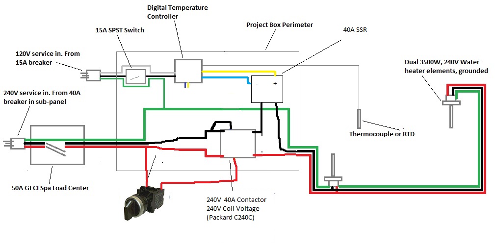
I would do something like this...Overall it adds only like $20 to your existing build, although it might end up being the same cost since i have no idea how expensive a 40A switch is. One 2 selector toggle switch to control the contactor coils to allow the 240V in. I am unsure what the yellow and blue wires were, i assume your SSR control output + and -, so i wired those to the SSR control pins. In reality on the 2 selector toggle its not coming in the left and out the right, the switch has two NC sides. You wire it up the input and output of one NC side(say the right) so when your switch is off(To the left) there are no wires even plugged in so no power gets to your coil but when you turn the switch to the right it opens and allows the hot(red) voltage through to your coil, completing the required 240V circuit with the black hot wire and activating the contactor allowing the red and black hot voltages through to your SSR which is then cycled on and off by your controller via its input pins. Hopefully that makes sense ;) Oh and i'd buy two and use the same 2 position selector switch for your 120V input as well.

MkoVHuY.jpg

This took longer than I anticipated, but I think I found the equipment I need. Please let me know if this is out of line. The key is:
1. American LED-gible SW-2837-420 22mm 2 Position Selector Switch: Amazon
2. Packard C240C 2 pole 40A, 208/240V Contactor: Amazon
3. SYL-2352 1/16 DIN PID Temp. Controller (for SSR) [1.89" x 1.89"] Accepts PT100 RTD input to 100mV/20mA. 12V DC output to SSR: Auber
4. MGR-1D4840 40A SSR, 3-32VDC input; 24-480VAC output: Auber

Edit: Of course, I did not include TC wiring or the wiring to the elements. Also will have the heat sink on the SSR

image.jpg
 
Yup looks correct.

But is there any specific reason your going with dual 3500W elements instead of just say a single 5500W element?
 
Yup looks correct.

But is there any specific reason your going with dual 3500W elements instead of just say a single 5500W element?

Thanks for all your help again!

Regarding the number of elements: I am not recirculating this water, and the cooler is long and narrow. I figured two shorter elements, staggered on either side, will reduce the likelihood of hot/cold spots.
 
Thanks for all your help again!

Regarding the number of elements: I am not recirculating this water, and the cooler is long and narrow. I figured two shorter elements, staggered on either side, will reduce the likelihood of hot/cold spots.

Sounds good, ill just note you already have 120V coming into your box and one of the cheap P38I plastic pumps for $20 would be better than nothing when your ready to upgrade.

If you havent already bought them i'd just get one 5500W element and a cheap plastic pump. Recirc is a pretty big deal in a HLT to get an accurate temperature reading. Otherwise you will always have hot and cold spots.
 
Back
Top